
wire rope construction chart quotation

In any cable or wire rope application, stretch may be a concern. There are two forms of stretch in cable and wire rope: Structural Stretch and Elastic Stretch.
Structural stretch is the lengthening of the lay in the construction of cable and wire rope as the individual wires adjust under load. Structural stretch in Loos and Company products is less than 1% of the total cable length. This form of stretch can be completely removed by applying a cable or wire rope prestretching operation prior to shipment.
Elastic stretch is the actual physical elongation of the individual wires under load. The elastic stretch can be calculated by using the following formula*:
Left hand lay or right hand lay describe the manner in which the strands are laid to form the rope. To determine the lay of strands in the rope, a viewer looks at the rope as it points away from them. If the strands appear to turn in a clockwise direction, or like a right-hand thread, as the strands progress away from the viewer, the rope has a right hand lay. The picture of steel wire rope on this page shows a rope with right hand lay. If the strands appear to turn in an anti-clockwise direction, or like a left-hand thread, as the strands progress away from the viewer, the rope has a left hand lay. (The rope in the left hand lay photo shows one left hand lay rope from left to right and top to bottom, with 5 right hand lay strands, and part of a sixth in the upper left. It is not 5 right hand lay ropes adjacent to each other.)
Ordinary and Ducay"s lay describe the manner in which the wires are laid to form a strand of the wire rope. To determine which has been used, first identify if left or right hand lay has been used to make the rope. Then identify if a right or left hand lay has been used to twist the wires in each strand. (On ordinary lay, the outer wires approximately follow the alignment of the rope: with Lang"s lay they are cross at an angle of about 45�.) Lang"s laid rope is able to flex over sheaves more easily (with less damage) but it has the disadvantage of having a high torque tendency (it tends to untwist when tension load is applied) compared with ordinary laid rope. Untwisting can be dangerous with a steel-cored rope: load is shed from the strands and may cause the core to fail as it becomes higher loaded. For this reason, swivel termination units can be dangerous.
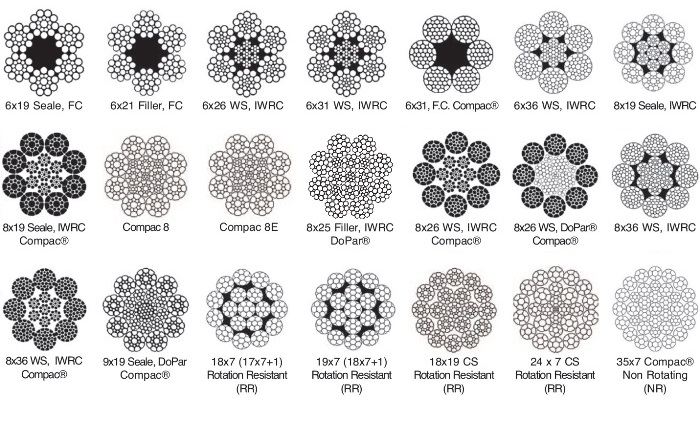
The specification of a wire rope type � including the number of wires per strand, the number of strands, and the lay of the rope � is documented using a commonly accepted coding system, consisting of a number of abbreviations.
We understand that there are many factors that go into choosing the correct sling, wire rope, rigging hardware or lifting device for a lift! Let our sales team help!
In this article, we outline important technical topics related to wire rope. This information has been sourced from and approved by Bridon American. Use the outline to skip to specific sections:
Any assembly of steel wires spun into a helical formation, either as a strand or wire rope (when subjected to a tensile load) can extend in three separate phases, depending on the magnitude of the applied load.
At the commencement of loading a new rope, extension is created by the bedding down of the assembled wires with a corresponding reduction in overall diameter. This reduction in diameter is accommodated by a lengthening of the helical lay. When sufficiently large bearing areas have been generated on adjacent wires to withstand the circumferential compressive loads, this mechanically created extension ceases and the extension in Phase 2 commences. The Initial Extension of any rope cannot be accurately determined by calculation and has no elastic properties.
The practical value of this characteristic depends upon many factors, the most important being the type and construction of rope, the range of loads and the number and frequency of the cycles of operation. It is not possible to quote exact values for the various constructions of rope in use, but the following approximate values may be employed to give reasonably accurate results.
Following Phase 1, the rope extends in a manner which complies approximately with Hookes Law (stress is proportional to strain) until the limit of proportionality or elastic limit is reached.
It is important to note that wire ropes do not possess a well defined Young’s Modulus of Elasticity, but an ‘apparent’ Modulus of Elasticity can be determined between two fixed loads.
By using the values given, it is possible to make a reasonable estimate of elastic extension, but if greater accuracy is required, it is advisable to carry out a modulus test on an actual sample of the rope. As rope users will find it difficult to calculate the actual metallic steel area, the values can be found in the Wire Rope Users Manual or obtained from Bridon Engineering.
The permanent, non-elastic extension of the steel caused by tensile loads exceeding the yield point of the material. If the load exceeds the Limit of Proportionality, the rate of extension will accelerate as the load is increased until a loading is reached at which continuous extension will commence, causing the wire rope to fracture without any further increase of load.
The coefficient of linear expansion (∝) of steel wire rope is (6.94 x 10⁻⁶ per °F) and therefore the change in length of 1 foot of rope produced by a temperature change of t (°F) would be:
Example: What will be the total elongation of a 200 ft. length of 1-1/8″ diameter Blue Strand 6 x 41 IWRC wire rope at a tension of 20,000 Ibs. and with an increase in temperature of 20°F?
In addition to bending stresses experienced by wire ropes operating over sheaves or pulleys, ropes are also subjected to radial pressure as they make contact with the sheave. This pressure sets up shearing stresses in the wires, distorts the rope’s structure and affects the rate of wear of the sheave grooves. When a rope passes over a sheave, the load on the sheave bearing results from the tension in the rope and the angle of rope contact. It is independent of the diameter of the sheave.
Assuming that the rope is supported in a well fitting groove, then the pressure between the rope and the groove is dependent upon the rope tension and diameter, but is independent of the arc of contact.
It must be realized that this method of estimation of pressure assumes that the area of contact of the rope in the groove is on the full rope diameter, whereas in fact only the crowns of the outer wires are actually in contact with the groove. It is estimated that the local pressures at these contact points may be as high as five times those calculated. If the pressure is high, the compressive strength of the material in the groove may be insufficient to prevent excessive wear and indentation, and this in turn will damage the outer wires of the rope and effect its working life.
As with bending stresses, stresses due to radial pressure increase as the diameter of the sheave decreases. Although high bending stresses generally call for the use of flexible rope constructions having relatively small diameter outer wires, these have less ability to withstand heavy pressures than do the larger wires in the less flexible constructions. If the calculated pressures are too high for the particular material chosen for the sheaves or drums or indentations are being experienced, consideration should be given to an increase in sheave or drum diameter. Such a modification would not only reduce the groove pressure, but would also improve the fatigue life of the rope.
The pressure of the rope against the sheave also causes distortion and flattening of the rope structure. This can be controlled by using sheaves with the correct groove profile, which, for general purposes, suggests a recommended groove diameter of nominal rope diameter +6%. The profile at the bottom of the groove should be circular over an angle of approximately 120° and the angle of flare between the sides of the sheave should be approximately 52°.
Bend fatigue testing of ropes usually consists of cycling a length of rope over a sheave while the rope is under a constant tension. As part of their ongoing development program, Bridon has tested literally thousands of ropes in this manner over the years on their own in-house design bend testing equipment.
Through this work, Bridon has been able to compare the effects of rope construction, tensile strength, lay direction, sheave size, groove profile and tensile loading on bend fatigue performance under ideal operating conditions. At the same time it has been possible to compare rope life to discard criteria (e.g. as laid down in ISO 4309) with that to complete failure of the rope, i.e. to the point where the rope has been unable to sustain the load any longer. As part of the exercise, it has also been possible to establish the residual breaking strength of the rope at discard level of deterioration.
What needs to be recognized, however, is that very few ropes operate under these controlled operating conditions, making it very difficult to use this base information when attempting to predict rope life under other conditions. Other influencing factors, such as dynamic loading, differential loads in the cycle, fleet angle, reeving arrangement, type of spooling on the drum, change in rope direction, sheave alignment, sheave size and groove profile, can have an equally dramatic effect on rope performance.
If designers or operators of equipment are seeking optimum rope performance or regard bending fatigue life as a key factor in the operation of equipment, such information can be provided by Bridon for guidance purposes.
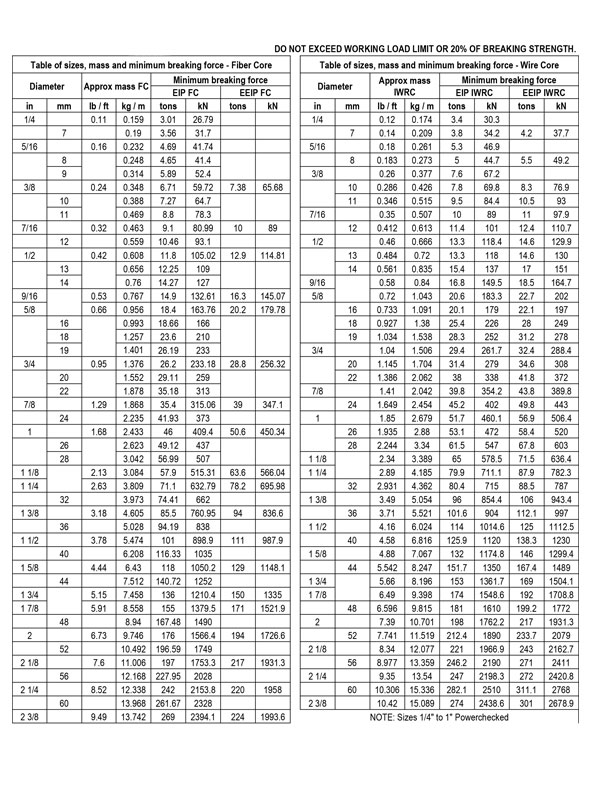
Wire ropes are manufactured slightly larger than the nominal diameter. The maximum allowable oversize tolerances provided by industry standards are shown in the following table:
Under certain circumstances it may be necessary to use a swivel in a lifting system to prevent rotation of the load. This is typically done for employee safety considerations. It is possible however, that the use of a swivel will have an adverse affect on rope performance and may, in some cases, damage the wire rope.
The type of swivel that causes the most concern from the standpoint of the wire rope is the independent anti-friction swivel that attaches directly to the rope. The purpose of using a swivel in a lifting system is to prevent rotation of the load. This then allows the wire rope to rotate. Excessive rope rotation can damage a wire rope.
To assist in determining whether or not a swivel should be used in the lifting system, the following recommendations should be considered. It must also be recognized that the rotation characteristics of different types and constructions of wire rope vary considerably. The following types and constructions of wire rope are grouped according to their rotation characteristics.
These rope constructions will rotate excessively with one end free to rotate, and the rope will unlay and distort and be easily damaged with a loss of rope breaking force.Blue Strand 6 x 19 and 6 x 36 Class Lang Lay
Wire rope constructions having high rotation characteristics when used in single part reeving may require a swivel in the system to prevent rotation in certain operating conditions. However, this should be done only when employee safety is the issue.
These rope constructions, when used in a reeving system with one end free to rotate, will have a high level of rotation. This will cause the rope to unlay and, to some degree, distortion of the rope will occur.Blue Strand 6 x 19 and 6 x 36—Class Regular Lay
The ropes in this Group are designed with an inner rope that is laid in the opposite direction to the outer strands to provide a medium resistance to rotation. Ropes with medium rotation characteristics are used with a swivel in single part reeving applications. However, a swivel is not recommended for multiple part hoisting applications or in any application where the swivel is not necessary for safety reasons. If it is necessary to use a swivel, the rope must be operating at a design factor of 5 or greater, must not be shock loaded and must be inspected daily by a qualified person for distortion.
It should be noted that if a swivel is used on conjunction with Group 3a ropes, rope service life might be reduced due to increased internal wear between the outer strands and the inner rope.Group 3aEndurance 8RR Rotation Resistant
Wire ropes having low rotation characteristics used in either single or multiple part reeving may be used with a swivel. The reason for this is that the ropes will exhibit very little, if any, rotation when used at the proper design factor. Application parameters, such as a fleet angle, may induce turn into a wire rope that can be relieved by the use of a swivel. However, if the application does not induce any turn into the rope, or if a swivel is not beneficial to the performance of the rope, the swivel may not be necessary.Endurance 35 LS
If the drum incorporates helical grooving, the helix angle of the groove needs to be added or subtracted from the fleet angle as described above to determine the actual fleet angle experienced by the rope.
When spooling rope onto a drum, it is generally recommended that the fleet angle is limited to between 0.5° and 2.5°. If the fleet angle is too small, i.e. less than 0.5°, the rope will tend to pile up at the drum flange and fail to return across the drum. In this situation, the problem may be alleviated by introducing a ‘kicker’ device or by increasing the fleet angle through the introduction of a sheave or spooling mechanism.
If the rope is allowed to pile up, it will eventually roll away from the flange, creating a shock load in both the rope and the structure of the mechanism, an undesirable and unsafe operating condition.
Excessively high fleet angles will return the rope across the drum prematurely, creating gaps between wraps of rope close to the flanges, as well as increasing the pressure on the rope at the cross-over positions.
Even where helical grooving is provided, large fleet angles will inevitably result in localized areas of mechanical damage as the wires ‘pluck’ against each other. This is often referred to as ‘interference’, but the amount can be reduced by selecting a Langs lay rope if the reeving allows. The “interference” effect can also be reduced by employing a Dyform rope, which offers a much smoother exterior surface than conventional rope constructions.
Where a fleet angle exists as the rope enters a sheave, it initially makes contact with the sheave flange. As the rope continues to pass through the sheave it moves down the flange until it sits in the bottom of the groove. In doing so, even when under tension, the rope will actually roll, as well as slide. As a result of the rolling action, the rope is twisted, i.e. turn is induced into or out of the rope, either shortening or lengthening the lay length of the outer layer of strands. As the fleet angle increases, so does the amount of twist.
To reduce the amount of twist to an acceptable level, the fleet angle should be limited to 2.5° for grooved drums and 1.5° for plain drums and when using Rotation Resistant, ropes the fleet angle should be limited to 1.5°.
However, for some crane and hoist applications, it is recognized that for practical reasons. It is not always possible to comply with these general recommendations, in which case, the rope life could be affected.
The problem of torsional instability in crane hoist ropes would not exist if the ropes could be perfectly torque balanced under load. The torque generated in a wire rope under load is usually directly related to the applied load by a constant ‘torque factor’. For a given rope construction, the torque factor can be expressed as a proportion of the rope diameter and this has been done below.
Variation with rope construction is relatively small and hence the scope for dramatically changing the stability of a hoisting system is limited. Nevertheless, the choice of the correct rope can have a deciding influence, especially in systems which are operating close to the critical limit. It should be noted that the rope torque referred to here is purely that due to tensile loading. No account is taken of the possible residual torque due, for example, to rope manufacture or installation procedures.
Torsional Stability and the Cabling Graph are two methods which can be used to determine torsional stability or the tendency of the rope to cable. The torque factors quoted are approximate maximum values for the particular constructions. To calculate the torque value for a particular rope size, multiply by the nominal rope diameter.
The torsional characteristics of wire rope will have the effect of causing angular displacement of a sheave block when used in multi-fall reeving arrangements. The formula below gives a good approximation under such arrangements.
The preceding equations are all relative to a simple two part reeving. For more complex systems, a similar approach may be used if account is taken of the different spacings of the ropes.
The equations assume that rope is torque-free in the noload condition, therefore, induced torque during or immediately after installation will adversely influence the calculated effect.
The above data assumes a constant torque value which is a valid assumption for a new rope. Wear and usage can have a significant effect on the torque value, but practical work shows that under such circumstances, the torque value will diminish, thus improving the stability of the arrangement. Some arrangements may be of such complexity that the evaluation demands a computer study.
Assuming a pedestal crane working on two falls is roped with 20mm diameter DYFORM 34LR and the bottom block carries a sheave of 360mm diameter with the falls parallel:
If the rope is new (worst condition) and no account is taken of block weight and friction then angular displacement for a height of lift of 30 meters is given by:
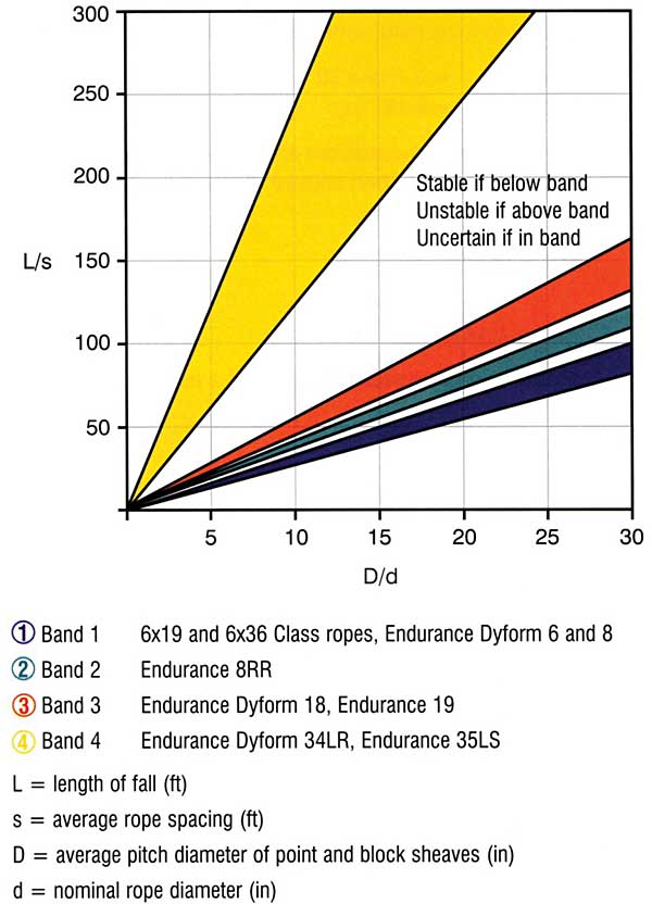
Field research jointly conducted by the Wire Rope Technical Board and the Power Crane and Shovel Association has shown that cabling of the rope parts in a multiple part reeved hoisting arrangement is controlled by several factors. The following calculations and graphs can be used to determine when and if cabling will occur on multiple part reeved hoisting arrangements.
Various constructions of rope shown on the graph indicate the limited conditions for torsional stability with the angular displacement of the hoist block to a maximum of 90 degrees. When the operating conditions for a particular installation give a resultant above the appropriate band, then cabling of the falls will most likely occur. If the operating conditions give a resultant below any particular band, the cabling of the falls will most likely not occur. If the operating conditions for any particular installation fall within the band, cabling is unpredictable.
Rotation resistant wire rope refers to a series of steel ropes which minimizes the tendency to spin or rotation under load. These wire ropes boast special design - the outer layer is twisted in the reverse direction of inner layers for counteracting torsional forces generated from multi-layers of strands.
To achieve the resistance against the spin and rotation, all wire ropes are composed of at least two layers of strands. In general, more layers a rotation resistant wire rope has, more resistance it will boast. For example, 2-layer ropes is much easier to spin and rotate than 3-layer ones. Meanwhile, if one end of free rotation is allowed, 2-layer rope can only develop 55% to 75% of its breaking strength comparing with 95% to 100% of 3-layer ropes.
The 3-layer rope with more outer strands is capable to distribute more radial pressure onto inner layers and ideal for larger mobile such as all tower cranes.
Wire ropes with 8 to 10 strands & 2-layer constructions without reversely twisted inner strands have very similar appearance to rotation resistant wire ropes, but they are not.
Rotation resistant wire ropes are considered to be less stable needing to be handled and installed with great care. They must be taken to avoid high loads with small diameter sheaves.

6 strands, nominally 19 wires per strand This class is the most widely used and is found in its many variations throughout many industries. With its good combination of flexibility and wear resistance, rope in this class is suited to the specific needs of many kinds of machinery and equipment. The designation 6x19 is only nominal; the number of wires ranges from 15 to 26. The following constructions are included in this class:
6x25 Filler Wire. In this construction, there are 19 main wires in each strand, plus six small filler wires. The filler wires are located between the outer layer of 12 wires and the inner layer of six. They provide support and stability to the strand. This construction is the best combination of flexibility and abrasion resistance found in the 6x19 Class.
6x19 Warrington. Each strand is made up of 19 wires. The outer layer of 12 wires has two different sizes of wire; the inner layer of six is one size of wire. The Warrington construction is somewhat less flexible than 6x25 Filler Wire, but more flexible than 6x21 Filler Wire.
6x21 Filler Wire. Each strand is made up of 21 wires. The rope has an outer layer of 10 large wires, an inner layer of five smaller wires and a still smaller center wire. There are five filler wires, located between the outer layer of ten wires and the inner layer of five. The 6x21 Filler Wire ropes are more wear-resistant but less flexible than Warrington, and less abrasion-resistant but more flexible than 6x19 Seale constructions.
6x26 Warrington Seale. This construction is composed of 26-wire strands. It has the same size outer wires as the 6x21 Filler Wire, with an inner wire configuration similar to the 6x36 Class ropes. Thus, it combines the wear resistance of a 6x19 rope with a flexibility between 6x19 and 6x36 Class ropes.
6x19 Seale. This construction has an outer layer of nine large wires, an inner layer of nine smaller wires and a single center wire. The Seale ropes are the least flexible of the 6x19 Class ropes. However, the large outer wires, solidly supported, provide resistance to abrasion and crushing.
The 6x36 Class of wire rope is characterized by the relatively large number of wires in each strand. Ropes of this class are more flexible than the 6x19 Class, but their resistance to abrasion is less than the 6x19 Class ropes.
The designation 6x36 is only nominal, as is the case with 6x19 Class. Ropes in the 6x36 Class may contain 27 to 49 wires per strand. Improvements in wire rope design, as well as changing machine designs, resulted in the use of strands with widely varying numbers of wires and geometry.
Larger wire ropes frequently incorporate a larger number of wires, resulting in a more complex geometry than found in the 6x19 or 6x36 Class wire ropes. WW’s 6x61 Class Bethlehem Mining Ropes generally are designed to comply with ASTM A 1023 geometry, although we added some innovations. WW strands the 6x61 Class Bethlehem Mining Ropes in a single operation, relying on dense, well fitted geometry to provide exceptional rope performance and the flexibility normally associated with 6x61 Class ropes.
The 6x61 Class ropes have a Seale-Filler Wire-Seale design, as shown in the cross sections below, containing from 50 to 77 wires per strand. WW further enhances Bethlehem Mining Rope performance by wire metallurgy and wire properties which are selectively modified to augment the specific rope geometries.
Many wire rope users have observed that heavily loaded ropes fail internally due to the failure of the IWRC. Such conditions illustrate that heavy IWRC stresses exist, which promote fewer fatigue cycles and create short rope life. WW designed Maxi-core to improve rope life under these conditions.
Maxi-core utilizes an IWRC design which features eight strands around a strand center. Maxi-core’s IWRC provides longer life, and, therefore, increases the overall service life of the rope. Because of its specialized IWRC, Maxi-core is resilient and able to accommodate shock loads better than conventional IWRC designs. Maxi-core also adds 33% more core support to the outer strands, thereby reducing internal stresses and promoting longer rope life. As with all Bethlehem Excavator Family Ropes, WW does not publish Maxi-core rope strengths. WW relies on specific rope improvements and specialized features to provide rope designs which give proven, superior field service.
This plastic jacket acts as a cushion or shock absorber between adjacent main strands and at main strand-to-IWRC contact points. The improved internal support is especially significant for ropes subjected to continual bending stresses and fluctuating loads (shock loading). Reduction of wear and damage at internal contact points results in longer and more predictable service life.
Compacted Strands: Beth Pac Beth Pac refers to rope manufactured by compacting each individual strand before closing the rope. In comparison to conventional wire rope, Beth Pac has a higher metallic area, improved crushing resistance and a smoother surface contacting sheaves and drums.
Beth Pac is offered in Excavator and Excavator-AR in diameters 21/4" through 23/4" in 8x36 construction for hoist ropes. Beth Pac can be combined with other Bethlehem Mining Rope features, such as En-core. For more information and help in determining your need for Beth Pac and other available sizes, please contact WW’s Sales and Engineering Departments.
BXL is furnished as right regular or lang lay, Form-set, IWRC wire rope manufactured in the 6x19, 6x36 and 8x36 Classes. Available grades are Excavator and Excavator-AR. For specific information, please refer to the table. For information on smaller diameters for mining applications, please contact our Customer Service Department.
BXL provides the characteristics common to Bethlehem Mining Rope, enhanced by the plastic-infusion. BXL starts with WW’s special wire grades used in the manufacture of mining rope. Excavator grade is designed to provide excellent resistance to bending fatigue, such as those conditions found with hoist ropes. Excavator-AR is intended for those applications where more abrasive operating conditions exist, such as in drag line applications. Enhanced by plastic infusion, BXL offers several improved features.
Improved fatigue resistance is one key feature of BXL. BXL’s polymer cushions each wire and strand, minimizing interstrand and interlayer nicking. BXL also offers improved abrasion resistance. The polymer acts as a barrier between the individual strands, preventing penetration of any adverse material, such as dust, dirt and metal particles. The polymer also distributes and reduces contact stresses between the rope and sheave, reducing the wire rope wear normally associated with uncoated wire rope. Perhaps the most important feature of BXL, however, is the polymer’s ability to maintain the balance of the rope. When a rope is in operation, or simply wound upon a drum, the rope’s components move and adjust accordingly.
Due to the nature of wire rope, this movement may cause accelerated wear, and in uncoated rope, may also produce a flattening or ovaling of the rope. The polymer in BXL minimizes this movement by locking the individual wires and strands in place. With the rope’s holding its intended shape during operation, operating stresses such as vibration are evenly distributed to all wires and strands, thereby reducing fatigue breaks and increasing service life.
This rope is particularly suitable where severe crushing and abrasion on a drum occur, or where a higher strength design is required than can be obtained with a similar round strand rope. The triangular strand shape not only provides better resistance to crushing, but also offers a greater exposed surface area for contact with sheaves, drums or underlying areas of spooled rope.
This feature, combined with Lang lay, distributes the abrasive wear over a greater number and longer length of wires. The broad, smooth surface of the rope also helps to minimize wear on drums and sheaves.
We make a full line of tail ropes customized to meet your requirements of strength and weight to balance your friction hoist system. Please contact your salesman or customer service with your specifications and we will supply a quotation to meet your needs.
This compacted wire rope construction is available in both galvanised and ungalvanised finish with either ordinary or langs lay. The construction family includes 32X7, 35X7 and 37X7. Depending upon your requirement for higher breaking load or better wear characteristics, these wire ropes are available in different finishes and lubrications as well as being available with plastic impregnated or in compacted constructions.
The 7x7x7 Cablaid Wire Rope is galvanized and preformed – good general purpose construction for strength and flexibility. Can be used over pulleys. TO BE USED FOR MECHANICALLY SWAGED SLINGS ONLY. Do not use for hand-spliced assemblies or for general purpose operating rope.
These ropes offer greater strength than standard ropes of the same diameter while providing greater resistance to drum crushing, scrubbing and similar wear. When producing our 6×26 Swaged rope, we utilize a rotary swaging process to produce a compact cross-section with minimum voids and greater surface area on outer wires.
For use in an application where a single-part hoist rope is used to lift a free load – or where rotation-resistant properties are essential for rope performance.
Our 8 strand constructions are regular lay and either 19 Seale or 25 Filler Wire. The size relationship between strands and cores gives these ropes increased bendability over six strand ropes of the same diameter.
Higher strength-to-diameter due to compacted wires in the strands. With increased metallic area, it provides rope strengths equal to 6-strand XXIP IWRC ropes of the same diameter.
Resistance to bending fatigue due to the uniformity of the wires within each strand. The strand’s outer surface is smooth, reducing contact pressures between the rope’s strands and radial pressures as it operates over sheaves and drums. This substantially cuts rope expense and extends service life.
In a multi-part wire rope system where the blocks have a tendency to twist–the 8 x 25 Resistwist rope has found successful application. The spin-resistant characteristic is achieved by laying the eight outer strands around an independent wire rope core so these strands are in opposite direction to the lay of the core. Thus, when the rope is in tension, opposing rotational forces are created between the core and the other strands. Though not as rotation-resistant, the 8 x 25 Resistwist is more stable than a 19 x 7 rope. It also has increased resistance to bending fatigue and crushing. This is achieved through the use of eight-strand construction with an independent wire rope core.

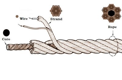
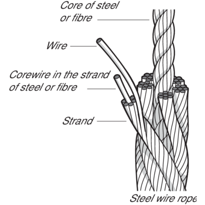
Wire rope can be seen everywhere around us, it is made of strands or bundles of individual wires constructed around an independent core, suitable for hoisting, towing, and anchoring heavy loads.
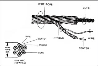
Wire rope is specified by the number of strands in the rope, the number of wires in each strand, and the strands are then twisted to form a rope construction.
The wire rope core is in the center of the rope and provide the rope stability, it is the foundation for the wire rope. Cores can be supplied with natural or synthetic fibers and steel core. For example, the 6×19 FC wire rope means that the rope has 6 strands, and there are 19 wires in each strand, the numbers 6×19 is followed by a letter combination, it means the core of the wire rope, FC means fiber core.
IWRC is commonly manufactured from 7 strands, while the WSC is manufactured from either 7 or 9 wires. Steel cores have a higher resistance to drum crushing and where less stretch and more strength is required.
The 6×19 FC wire rope means that the rope has 6 strands, and there are 19 wires in each strand, however, 6 x 19 wire rope may not reflect the actual construction, for 6 x 21 wire rope, and 6 x 26 are designated as being in the 6 x 19 classification, despite none of their constructions contain 19 wires.
There are many different wire rope grades, the higher grade, the higher min breaking strength, commonly the grades of wire rope are available include Improved Plow Steel (IPS), Extra Improved Plow Steel (EIPS), Extra Extra Improved Plow Steel (EEIPS), and metric wire rope grades can be designated as 1770n/mm²(Improved Plow Steel), 1960n/mm²(Extra Improved Plow Steel) and 2160n/mm²(Extra Extra Improved Plow Steel).
There are main three protective coatings on the wire rope, zinc-coated (galvanized) wire rope for harsh environment, uncoated steel (bright) wire rope for most running supplied, and stainless steel wire rope for marine and architectural applications.
The type and direction of lay wire rope mean the wires are laid around the strands(regular lay or lang lay) and the direction in which the strands are laid around the core(a right or left hand).
Regular lay is also referred to as ordinary lay. The strands are twisted in one direction, either left or right across the core and the wires are laid in opposite direction to the lay of the strands, which causes the finished product to appear like the wires are running parallel to the axis of the rope.
The regular lay wire rope is more flexible and carries better resistance to crushing forces and is more naturally rotation-resistant and spool better on a drum than lang lay wire rope.
The lang lay wire rope indicates that the wire lay and strand lay around the core in the same direction, either right or left and causes the finished product to appear with the wires to form an angle with the axis of the rope. Thes lang lay ropes are generally more flexible and have increased abrasion resistance leading to a longer lifespan than regular lay ropes, which can be used in construction, excavating, and mining applications.
Our stainless-steel aircraft cable consists of thin steel wires that are stranded together to give the cable a combination of flexibility and strength. Although the largest diameter of aircraft cable available at Tyler Madison maxes out at a ¼”, it is lightweight and strong enough to meet special airline safety standards.
Commercial quality "aircraft grade" cable is made from galvanized steel wire or stainless steel wire. Galvanized aircraft cable provides high tensile strength and adequate corrosion resistance for most commercial applications. Stainless steel cable provides slightly lower tensile strength, but greater resistance to corrosion. We also offer aircraft cable fitting services.
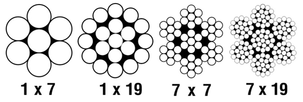
Cable or wire rope is fabricated from individual wires put together in a uniform helical arrangement to form what is called a strand. A strand typically contains 7 wires (1 x 7) or 19 wires (1 x 19), although others are available. Cable or wire rope contains a varying number of these strands such as 7 x 7 and 7 x 19 (number of strands x wire per strand). The more strands and more wires per strand, the more flexible the cable and the higher the cost. The greater the cable diameter, the greater the diameter of each wire and the greater the breaking strength.
At Tyler Madison Inc., aircraft cable assemblies are just one of the many quality wire rope products that we manufacture for our industrial and commercial customers . We have the ability to create fully customized cable assemblies with standard or custom aircraft cable fittings. With skilled labor and precise advanced equipment, we are able to manufacture quality wire ropes and high-strength cables at an affordable price. Along the way, we can help you design and engineer aircraft cable fittings for your application. If you have an idea of what kind of aviation cable assembly or wire rope you need, but aren"t sure how to make it a reality, just contact Tyler Madison today and we will be ready to help!
No matter how customized the cable, wire rope or aircraft cable fittings for your application needs to be, we are more than capable of helping you get the job done!
For more information or inquiries about our wire rope or aircraft cable fittings, get in touch with us today. Our team of experts are here to answer any of your questions. We look forward to hearing from you!


 8613371530291