
wire rope construction details free sample

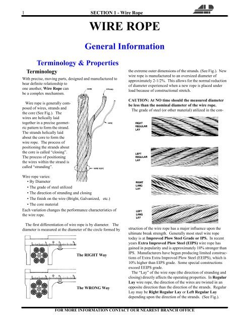
Asteel wire rope is defined not only by its basic elements (wires, strands, core), but also by the way in which the individual wires are laid together to create a strand and the way in which the strands are laid around the core, etc. The steel wire rope’s construction is defined when the following criteria have been determined:
The steel wire rope is designated according to the number of strands, the number of wires in each strand, the design (type) of the strand, and the type of core.
The number of wires in a strand varies between three and approx. 139, although there are most commonly 7, 19, 24 or 36 wires. The number of wires and their thickness depend on the design of the strand and affects the characteristic of the steel wire rope.
The type of strand is characterised by the way in which the wires in the strand are arranged. There are four basic types of strand design that are used in all steel wire ropes, either in their original form or as a combination of two or more types. The four basic types are:
The Standard construction (fig. 3) is characterised by the fact that all wires are of equal thickness, although the core wire may be thicker. The wires are also laid together in such a way that all of them, with the exception of the centre wire, are of equal length. In this way all the wires are subjected to an equal distribution of load when pulled straight.
The geometric wire distribution consists of one centre wire, onto which one or more layers are laid. Each layer is produced in a separate operation. If there are several layers, the number of wires increases by six for each layer.
The designation for a Standard strand with e.g. seven wires is (1-6), i.e. one centre wire with six external wires in one operation. If there are 37 wires it is known as (1-6/12/18), i.e. one centre wire with six external wires from the first operation, 12 from the second operation and 18 from the third operation.
The Seale construction (fig. 5) is characterised by the way in which the strand consists of two layers of wire produced in one operation. Also, the number of wires in the first and second layer is identical.This construction is somewhat stiffer than a corresponding Standard construction (with the same number of wires). This is because the outer wires in the Seale construction are considerably thicker.
The Filler construction (fig. 7) is characterised by a strand consisting of two layers of wires produced in one operation. Also, the number of wires in the second layer is twice the number in the first layer. This is, however, only possible if filler wires are inserted between the first and the second layers, to prevent the strand becoming hexagonal in shapes.
This construction is more flexible than a corresponding Standard construction and considerably more flexible than a corresponding Seale construction (with the same number of wires excluding filler wires).
A Filler strand with e.g. 25 wires (including 6 filler wires) is known as (1-6+6F-12), i.e. one centre wire with six wires in the first layer and 12 wires in the second layer. There are six filler wires between the first and the second layers.
The Warrington construction (fig. 9) is characterised by a strand consisting of two layers of wire produced in one operation. The second (outer) layer contains wires of two dimensions, and the number of wires in the second layer is twice the number in the first.
This construction is very compact and flexible. A Warrington strand with e.g. 19 wires is known as (1-6-6+6), i.e. one centre wire with six wires in the first layer and a total of 12 wires of two dimensions in the second layer. The centre wire may be replaced by several wires or a fibre core (fig. 10).
The Warrington-Seale construction is characterised by a strand consisting of three layers of wire produced in one operation. The number of wires in the third (outer) layer matches the number of wires in the second layer. Also, the layers below the outer layer are built as a Warrington construction.
A Warrington-Seale strand with e.g. 36 wires is known as (1-7-7+7-14), i.e. one centre wire with seven wires in the first layer, 14 wires made up of two dimensions in the second layer, and 14 wires in the third layer.
The strands and the wires in the strands do not necessarily have to be round. Examples of this are shown in fig. 12. The strands are special strands (i.a. with profiled wire), designed to meet extremely unusual requirements.
The number of strands in a steel wire rope varies between three and approx. 36, although most commonly there are six strands. The more strands a steel wire rope contains, the more rounded and flexible it is, although the wires in the strand are also thinner (less durable).
Fibre cores are the most commonly used, as not only do they provide a good, elastic base but also enable lubrication of the rope from the inside, since it is possible to add oil and/or grease to the fibre core during production. This reduces the risk of rust attacking from the inside. The fibre core is normally produced from polypropylene (PP) or sisal. PP can withstand weaker acids and alkalis and it does not rot. The advantage of a sisal core is that it can absorb oil/grease to a greater degree for lubrication of the steel wire rope from the inside.
Randers Reb recommends the use of a steel core, in the event that it is not certain that a fibre core will provide satisfactory support for the strands, e.g. if thesteel wire rope is spooled on to a drum in several layers under a considerable load, or at high temperatures.
The word “lay” has more than one meaning in this context. It is used to describe the process of interweaving the wires and strands and also to describe the appearance of the finished steel wire rope. The four most common terms to describe the lay of a steel wire rope are:
Right hand regular lay steel wire rope. In this instance the wires in the strand are laid in the opposite direction to the strands in the rope. The wires are laid helically left, while the strands are laid helically right (see fig. 13).
Right hand Lang lay steel wire rope. Here the wires are laid in the same direction as the strands in the rope. The wires in the strands and the strands are laid helically right (see fig. 15).
Multi layer steel wire rope (low rotation/rotation resistant). Here there are usually two layers of strands, the inner layer as a rule a left hand Lang lay, while the outer layer is a right hand regular lay.
Cable laid steel wire rope. The strands are normally 6-lay steel wire rope with a fibre or steel core. The core is a fibre core or a 6-lay steel wire rope with a fibre or steel core.
Flat braided steel wire rope. This steel wire rope is flat braided from strands or consists of parallel strands or steel wire ropes that are bound together by sewing (belt strap).
Right hand lay steel wire rope is also known as Z-lay, and left hand as S-lay. Similarly, a right hand lay strand is known as z-lay and left hand as s-lay. Fig. 17 shows why. Of the types of lay described, right hand regular lay is the most common.
“Preformed” refers to steel wire ropes in which the strands have been permanently formed during the laying process (see fig. 18), so that they are completely stress-free within the unloaded steel wire rope.
All Randers Reb steel wire ropes are supplied preformed, with the exception of certain individual special constructions (e.g. low-rotation/rotation resistant).
Wire rope and cable are each considered a “machine”. The configuration and method of manufacture combined with the proper selection of material when designed for a specific purpose enables a wire rope or cable to transmit forces, motion and energy in some predetermined manner and to some desired end.
Two or more wires concentrically laid around a center wire is called a strand. It may consist of one or more layers. Typically, the number of wires in a strand is 7, 19 or 37. A group of strands laid around a core would be called a cable or wire rope. In terms of product designation, 7 strands with 19 wires in each strand would be a 7×19 cable: 7 strands with 7 wires in each strand would be a 7×7 cable.
Materials Different applications for wire rope present varying demands for strength, abrasion and corrosion resistance. In order to meet these requirements, wire rope is produced in a number of different materials.
Stainless Steel This is used where corrosion is a prime factor and the cost increase warrants its use. The 18% chromium, 8% nickel alloy known as type 302 is the most common grade accepted due to both corrosion resistance and high strength. Other types frequently used in wire rope are 304, 305, 316 and 321, each having its specific advantage over the other. Type 305 is used where non-magnetic properties are required, however, there is a slight loss of strength.
Galvanized Carbon Steel This is used where strength is a prime factor and corrosion resistance is not great enough to require the use of stainless steel. The lower cost is usually a consideration in the selection of galvanized carbon steel. Wires used in these wire ropes are individually coated with a layer of zinc which offers a good measure of protection from corrosive elements.
Cable Construction The greater the number of wires in a strand or cable of a given diameter, the more flexibility it has. A 1×7 or a 1×19 strand, having 7 and 19 wires respectively, is used principally as a fixed member, as a straight linkage, or where flexing is minimal.
Cables designed with 3×7, 7×7 and 7×19 construction provide for increasing degrees of flexibility but decreased abrasion resistance. These designs would be incorporated where continuous flexing is a requirement.
Selecting Wire Rope When selecting a wire rope to give the best service, there are four requirements which should be given consideration. A proper choice is made by correctly estimating the relative importance of these requirements and selecting a rope which has the qualities best suited to withstand the effects of continued use. The rope should possess:Strength sufficient to take care of the maximum load that may be applied, with a proper safety factor.
Strength Wire rope in service is subjected to several kinds of stresses. The stresses most frequently encountered are direct tension, stress due to acceleration, stress due to sudden or shock loads, stress due to bending, and stress resulting from several forces acting at one time. For the most part, these stresses can be converted into terms of simple tension, and a rope of approximately the correct strength can be chosen. As the strength of a wire rope is determined by its, size, grade and construction, these three factors should be considered.
Safety Factors The safety factor is the ratio of the strength of the rope to the working load. A wire rope with a strength of 10,000 pounds and a total working load of 2,000 pounds would be operating with a safety factor of five.
It is not possible to set safety factors for the various types of wire rope using equipment, as this factor can vary with conditions on individual units of equipment.
The proper safety factor depends not only on the loads applied, but also on the speed of operation, shock load applied, the type of fittings used for securing the rope ends, the acceleration and deceleration, the length of rope, the number, size and location of sheaves and drums, the factors causing abrasion and corrosion and the facilities for inspection.
Fatigue Fatigue failure of the wires in a wire rope is the result of the propagation of small cracks under repeated applications of bending loads. It occurs when ropes operate over comparatively small sheaves or drums. The repeated bending of the individual wires, as the rope bends when passing over the sheaves or drums, and the straightening of the individual wires, as the rope leaves the sheaves or drums, causing fatigue. The effect of fatigue on wires is illustrated by bending a wire repeatedly back and forth until it breaks.
The best means of preventing early fatigue of wire ropes is to use sheaves and drums of adequate size. To increase the resistance to fatigue, a rope of more flexible construction should be used, as increased flexibility is secured through the use of smaller wires.
Abrasive Wear The ability of a wire rope to withstand abrasion is determined by the size, the carbon and manganese content, the heat treatment of the outer wires and the construction of the rope. The larger outer wires of the less flexible constructions are better able to withstand abrasion than the finer outer wires of the more flexible ropes. The higher carbon and manganese content and the heat treatment used in producing wire for the stronger ropes, make the higher grade ropes better able to withstand abrasive wear than the lower grade ropes.
Effects of Bending All wire ropes, except stationary ropes used as guys or supports, are subjected to bending around sheaves or drums. The service obtained from wire ropes is, to a large extent, dependent upon the proper choice and location of the sheaves and drums about which it operates.
A wire rope may be considered a machine in which the individual elements (wires and strands) slide upon each other when the rope is bent. Therefore, as a prerequisite to the satisfactory operation of wire rope over sheaves and drums, the rope must be properly lubricated.
Loss of strength due to bending is caused by the inability of the individual strands and wires to adjust themselves to their changed position when the rope is bent. Tests made by the National Institute of Standards and Technology show that the rope strength decreases in a marked degree as the sheave diameter grows smaller with respect to the diameter of the rope. The loss of strength due to bending wire ropes over the sheaves found in common use will not exceed 6% and will usually be about 4%.
The bending of a wire rope is accompanied by readjustment in the positions of the strands and wires and results in actual bending of the wires. Repetitive flexing of the wires develops bending loads which, even though well within the elastic limit of the wires, set up points of stress concentration.
The fatigue effect of bending appears in the form of small cracks in the wires at these over-stressed foci. These cracks propagate under repeated stress cycles, until the remaining sound metal is inadequate to withstand the bending load. This results in broken wires showing no apparent contraction of cross section.
Experience has established the fact that from the service view-point, a very definite relationship exists between the size of the individual outer wires of a wire rope and the size of the sheave or drum about which it operates. Sheaves and drums smaller than 200 times the diameter of the outer wires will cause permanent set in a heavily loaded rope. Good practice requires the use of sheaves and drums with diameters 800 times the diameter of the outer wires in the rope for heavily loaded fast-moving ropes.
It is impossible to give a definite minimum size of sheave or drum about which a wire rope will operate with satisfactory results, because of the other factors affecting the useful life of the rope. If the loads are light or the speed slow, smaller sheaves and drums can be used without causing early fatigue of the wires than if the loads are heavy or the speed is fast. Reverse bends, where a rope is bent in one direction and then in the opposite direction, cause excessive fatigue and should be avoided whenever possible. When a reverse bend is necessary larger sheaves are required than would be the case if the rope were bent in one direction only.
Stretch of Wire Rope The stretch of a wire rope under load is the result of two components: the structural stretch and the elastic stretch. Structural stretch of wire rope is caused by the lengthening of the rope lay, compression of the core and adjustment of the wires and strands to the load placed upon the wire rope. The elastic stretch is caused by elongation of the wires.
The structural stretch varies with the size of core, the lengths of lays and the construction of the rope. This stretch also varies with the loads imposed and the amount of bending to which the rope is subjected. For estimating this stretch the value of one-half percent, or .005 times the length of the rope under load, gives an approximate figure. If loads are light, one-quarter percent or .0025 times the rope length may be used. With heavy loads, this stretch may approach one percent, or .01 times the rope length.
The elastic stretch of a wire rope is directly proportional to the load and the length of rope under load, and inversely proportional to the metallic area and modulus of elasticity. This applies only to loads that do not exceed the elastic limit of a wire rope. The elastic limit of stainless steel wire rope is approximately 60% of its breaking strength and for galvanized ropes it is approximately 50%.
Preformed Wire Ropes Preformed ropes differ from the standard, or non-preformed ropes, in that the individual wires in the strands and the strands in the rope are preformed, or pre-shaped to their proper shape before they are assembled in the finished rope.
This, in turn, results in preformed wire ropes having the following characteristics:They can be cut without the seizings necessary to retain the rope structure of non-preformed ropes.
They are substantially free from liveliness and twisting tendencies. This makes installation and handling easier, and lessens the likelihood of damage to the rope from kinking or fouling. Preforming permits the more general use of Lang lay and wire core constructions.
Removal of internal stresses increase resistance to fatigue from bending. This results in increased service where ability to withstand bending is the important requirement. It also permits the use of ropes with larger outer wires, when increased wear resistance is desired.
Outer wires will wear thinner before breaking, and broken wire ends will not protrude from the rope to injure worker’s hands, to nick and distort adjacent wires, or to wear sheaves and drums. Because of the fact that broken wire ends do not porcupine, they are not as noticeable as they are in non-preformed ropes. This necessitates the use of greater care when inspecting worn preformed ropes, to determine their true condition.
Nantong Fasten Metals Products Co., LTD is located in the coastal open city—Nantong which is in the lower area of the Yangtze River. We are a professional corporation which produces a variety of standards and types of galvanized steel wire rope, ungalvanized steel wire rope, steel-wire, stranded wire and spring steel wire. Our products mainly exported to Southeast Asia, the United States, Europe, the Middle East, Africa and other countries.
Rotation resistant wire rope refers to a series of steel ropes which minimizes the tendency to spin or rotation under load. These wire ropes boast special design - the outer layer is twisted in the reverse direction of inner layers for counteracting torsional forces generated from multi-layers of strands.
To achieve the resistance against the spin and rotation, all wire ropes are composed of at least two layers of strands. In general, more layers a rotation resistant wire rope has, more resistance it will boast. For example, 2-layer ropes is much easier to spin and rotate than 3-layer ones. Meanwhile, if one end of free rotation is allowed, 2-layer rope can only develop 55% to 75% of its breaking strength comparing with 95% to 100% of 3-layer ropes.
The 3-layer rope with more outer strands is capable to distribute more radial pressure onto inner layers and ideal for larger mobile such as all tower cranes.
Wire ropes with 8 to 10 strands & 2-layer constructions without reversely twisted inner strands have very similar appearance to rotation resistant wire ropes, but they are not.
Rotation resistant wire ropes are considered to be less stable needing to be handled and installed with great care. They must be taken to avoid high loads with small diameter sheaves.

Wire rope is a complex mechanical device that has many moving parts, all working in tandem to help support and move an object or load. In the lifting and rigging industries, wire rope is attached to a crane or hoist and fitted with swivels, shackles or hooks to attach to a load and move it in a controlled matter. It can also be used to lift and lower elevators, or as a means of support for suspension bridges or towers.
A wire rope is a machine with many moving parts. It has a unique design consisting of steel wires that form individual strands laid in a helical pattern around a center core.
Wire rope is a preferred lifting device for many reasons. Its unique design consists of multiple steel wires that form individual strands laid in a helical pattern around a core. This structure provides strength, flexibility and the ability to handle bending stresses. Different configurations of the material, wire, and strand structure will provide different benefits for the specific lifting application, including:
However, selecting the proper wire rope for your lifting application requires some careful thought. Our goal is to help you understand the components of a wire rope, the construction of wire rope and the different types of wire rope and what they might be used for. This will allow you to select the best performing and longest-lasting wire rope for the job at hand.
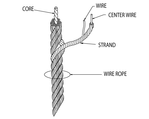
A finished wire rope is comprised of individual wires, which make up individual strands, which are then laid in a helical pattern around a synthetic or steel core.
A wire rope is a machine with many moving parts. From childhood, many of us have been conditioned to think of a machine as some device with gears, shafts, belts, cams and assorted whirring parts. Yet, by the rules of physics, an ordinary pry bar is a simple machine, even though it has only one part.
A wire rope is, in reality, a very complicated machine. A typical 6 by 25 rope has 150 wires in its outer strands, all of which move independently and together in a very complicated pattern around the core as the rope bends. Clearances between wires and strands are balanced when a rope is designed so that proper bearing clearances will exist to permit internal movement and adjustment of wires and strands when the rope has to bend. These clearances will vary as bending occurs, but are of the same range as the clearances found in automobile engine bearings.
Understanding and accepting the “machine idea” gives a rope user a greater respect for rope, and enables them to obtain better performance and longer useful life from rope applications. Wire rope is a complex piece of mechanical machinery with a number of different specifications and properties that can affect its performance and service life.
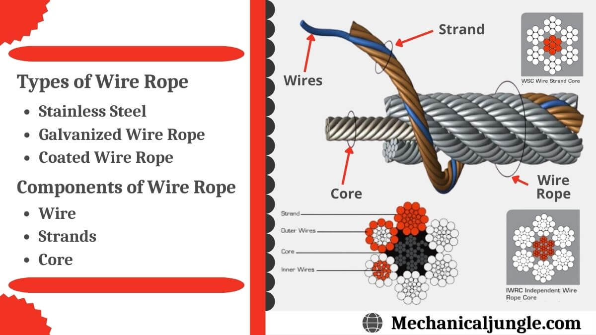
A finished wire rope is comprised of individual wires, which make up individual strands, which are then laid in a helical pattern around a synthetic or steel core. There are four basic components that make up the design of a finished wire rope:
Wires are the smallest component of wire rope and they make up the individual strands in the rope. Wires can be made from a variety of metal materials including steel, iron, stainless steel, monel, and bronze. The wires can be manufactured in a variety of grades that relate to the strength, resistance to wear, fatigue resistance, corrosion resistance, and curve of the wire rope.
Strands of wire rope consist of two or more wires arranged and twisted in a specific arrangement. The individual strands are then laid in a helical pattern around the core of the rope. Strands made of larger diameter wires are more resistant to abrasion, while strands made of smaller diameter wires are more flexible.
The core of a wire rope runs through the center of the rope and supports the strands and helps to maintain their relative position under loading and bending stresses. Cores can be made from a number of different materials including natural or synthetic fibers and steel.
The construction of wire rope falls into one of these strand pattern classifications. The number of layers of wires, the number of wires per layer, and the size of the wires per layer all affect the strand pattern type. Wire rope can be constructed using one of the following patterns, or can be constructed using two or more of the patterns below.
Filler Wire – Two layers of uniform-size wire around a center with the inner layer having half the number of wires as the outer layer. Small filler wires, equal to the number in the inner layer, are laid in valleys of the inner wire.
Seale – Two layers of wires around a center with the same number of wires in each layer. All wires in each layer are the same diameter. The large outer wires rest in the valleys between the smaller inner wires.
Warrington – Two layers of wires around a center with one diameter of wire in the inner layer, and two diameters of wire alternating large and small in the outer later. The larger outer-layer wires rest in the valleys,and the smaller ones on the crowns of the inner layer.
Remember, wire rope is a complex piece of mechanical machinery. There are a number of different specifications and properties that can affect the performance and service life of wire rope. Consider the following when specifying the best type of wire rope for your lifting application:
When you select a piece of rope that is resistant to one property, you will most likely have a trade-off that affects another property. For example, a fiber core rope will be more flexible, but may have less crushing resistance. A rope with larger diameter wires will be more abrasion resistant, but will offer less fatigue resistance.
A rope with larger diameter wires will be more crush resistant and abrasion resistant, while a rope with smaller diameter wires will be more bendable and fatigue resistant.
On a preformed wire rope, the strands and wires are formed during the manufacturing process to the helical shape that they will take in a finished wire rope. Preformed rope can be advantageous in certain applications where it needs to spool more uniformly on a drum, needs greater flexibility, or requires more fatigue-resistance when bending.
Direction and type of lay refer to the way the wires are laid to form a strand (either right or left) and how the strands are laid around the core (regular lay, lang lay, or alternate lay).
Regular Lay – The wires line up with the axis of the rope. The direction of the wire lay in the strand is opposite to the direction of the strand lay. Regular lay ropes are more resistant to crushing forces, are more naturally rotation-resistant, and also spool better in a drum than lang lay ropes.
Lang Lay – The wires form an angle with the axis of the rope. The wire lay and strand lay around the core in the same direction. Lang Lay ropes have a greater fatigue-resistance and are more resistant to abrasion.
A steel core can be an independent wire rope or an individual strand. Steel cores are best suited for applications where a fiber core may not provide adequate support, or in an operating environment where temperatures could exceed 180° F.
The classifications of wire rope provide the total number of strands, as well as a nominal or exact number of wires in each strand. These are general classifications and may or may not reflect the actual construction of the strands. However, all wire ropes of the same size and wire grade in each classification will have the same strength and weight ratings and usually the same pricing.
Some types of wire rope, especially lang lay wire rope, are more susceptible to rotation when under load. Rotation resistant wire rope is designed to resist twisting, spinning, or rotating and can be used in a single line or multi-part system. Special care must be taken when handling, unreeling, and installing rotation resistant wire rope. Improper handling or spooling can introduce twist into the rope which can cause uncontrolled rotation.
Compacted strand wire rope is manufactured using strands that have been compacted, reducing the outer diameter of the entire strand, by means of passing through a die or rollers. This process occurs prior to closing of the rope.This process flattens the surface of the outer wires in the strand, but also increases the density of the strand. This results in a smoother outer surface and increases the strength compared to comparable round wire rope (comparing same diameter and classification), while also helping to extend the surface life due to increased wear resistance.
A swaged wire rope differs from a compacted strand wire rope, in that a swaged wire rope’s diameter is compacted, or reduced, by a rotary swager machine after the wire rope has been closed. A swaged wire rope can be manufactured using round or compacted strands.The advantages of a swaged wire rope are that they are more resistant to wear, have better crushing resistance, and high strength compared to a round strand wire rope of equal diameter and classification. However, a swaged wire rope may have less bending fatigue resistance.
A plastic coating can be applied to the exterior surface of a wire rope to provide protection against abrasion, wear, and other environmental factors that may cause corrosion. However, because you can’t see the individual strands and wires underneath the plastic coating, they can be difficult to inspect.
Plastic filled wire ropes are impregnated with a matrix of plastic where the internal spaces between the strands and wires are filled. Plastic filling helps to improve bending fatigue by reducing the wear internally and externally. Plastic filled wire ropes are used for demanding lifting applications.
This type of wire rope uses an Independent Wire Rope Core (IWRC) that is either filled with plastic or coated in plastic to reduce internal wear and increase bending fatigue life.


 8613371530291