
wire rope crash barrier free sample

Before beginning, we strongly recommend you read https://www.vcrashusa.com/blog/2018/6/7/building-complex-systems-with-joint-tools to better understand working with joints in Virtual CRASH. You can learn more about joint stiffness and damping coefficients in the Short Glossary.
It is recommended to construct your own cable object first, rather than using the rope tool, as this reduces unneeded spherical joint connections which can slow down the simulation calculations.
We have the option of simulating posts and tying the cables to the posts, or we can simply tie the cables to a plane that’s been converted to a terrain object. First, place a plane object beneath the region where the cable barrier is set up. Convert the plane to a terrain object (Create > Physics > Make Unyielding / Terrain from Selection).
See “Development of Advanced Finite Element Material Models for Cable Barrier Wire Rope” for examples of using test bogies to better understand cable tension responses to bogie penetration.
You may notice, depending on how you set up your simulation, that one or more cables travel laterally through the tires of your vehicle. This happens, of course, because the simulated wheel objects are not solid objects which can interact arbitrarily with the environment. The issue of lateral wheel interaction is discussed in a few other places in the vCRASH Academy. For example, see:
Note, using this workflow, it is important to first center the vehicle mesh and ellipsoids or any other objects at x=0, y=0 before making the group object. In the example above, we’re included an ellipsoid in our group to round the bottom portion of the vehicle so that there is smooth and continuous contact with the cable barriers. This also prevents the cables from going through the wheels. Note, a blue ellipsoid was included in the group object to smooth contact between the side mirror and the upper cable. These ellipsoids can be hidden from view.
They are designed to redirect the vehicle and have a lower severity than the roadside hazard they protect. There are several types of safety barrier (but within these types there are different systems which have their own specific performance characteristics).
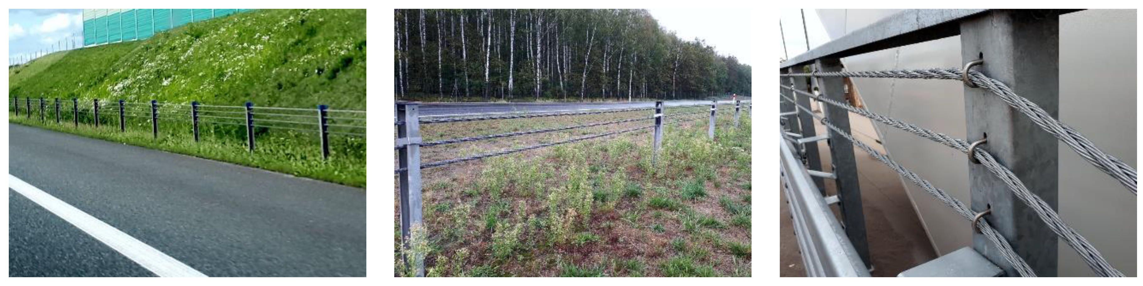
Flexible barriers are made from wire rope supported between frangible posts. Flexible barriers may be the best option for minimizing injuries to vehicle occupants, however they may pose a risk to motorcyclists. These barriers deflect more than other barrier types and need to be repaired following impact to maintain their re-directive capability.
Semi-rigid barriers are usually made from steel beams or rails. These deflect less than flexible barriers and so they can be located closer to the hazard when space is limited. Depending on the impact these barriers may be able to redirect secondary impacts.
Rigid barriers are usually made of concrete and do not deflect. Rigid barriers should be used only where there is no room for deflection of a semi-rigid or flexible barrier. Rigid barriers are often utilized at high volume roadwork sites to protect road workers or other road users particularly where another barrier type is awaiting repair. Currently (depending on their height and other details) these provide the highest level of containment of heavy vehicles. In most cases following impact these barriers require little or no maintenance.
Vehicle parapets are rigid barriers in steel, concrete or a combination of both. They are installed onto highway structures such as bridges, retaining walls or building facilities. Their main purpose is to restrain an errant vehicle from falling off the structures.
Much of the benefit from the use of barriers comes from a reduction in crash severity. Although a crash may still occur, it is likely to have a safer consequence than colliding with the object that the barrier is protecting.
On existing roads retrofit of safety barriers can be challenging due to incompatibility between road layout, ground condition, roadside space, etc. and technical criteria for the installation of safety barriers. In these circumstances, solutions are often context-sensitive and may need to be tailored-made. Solutions for existing roads should be formulated with on-site surveys, comparison of options and risk assessments.
In dense urban areas where the roadside is needed for crossing, access to vehicles and loading or unloading activities, bollards may be a means to protect pedestrians from errant vehicles. However, rigid bollards may not be forgiving at high speed except for products designed to concurrently attenuate an impact.Barrier end terminals
The need for end terminals arises from the deployment of safety barriers. Collision with untreated end terminals can result in lead to violent deceleration or penetration of the barrier into the compartment. On the other hand, a sloping barrier end can launch an errant vehicle into the air followed by rollover, falling off a drop or collision with rigid objects. All these scenarios have high potential for severe injuries to occupants of an errant vehicle.
The first step is to minimise the number of end terminals or relocate them to safer positions:Closing short gaps between two sections of the same safety barriers.
The remaining sites should be addressed by the following measures:Extending and flaring the safety barrier to blend in with an upstream slope or anchor to an abutment wall.
Sloping end of W-beam barriers of gentle gradient anchored into the ground may be an acceptable treatment. At low to moderate speed, an errant vehicle may ride over the barrier. There should not be major roadside hazards which can be reached by the errant vehicle.
Openings are sometimes needed along a safety barrier for emergency refuge, evacuation, operation or maintenance. These openings may be provided by an overlapping barrier layout such that the leading end terminal of the second barrier is shielded by the trailing section of the upstream barrier. However, this arrangement may not be suitable for undivided road where an errant vehicle may encroach onto the roadside from the opposite direction.
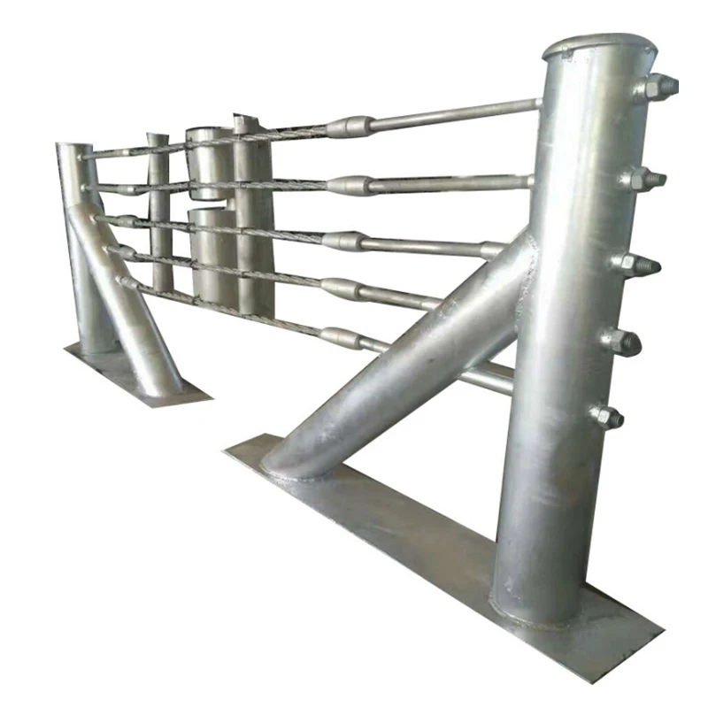
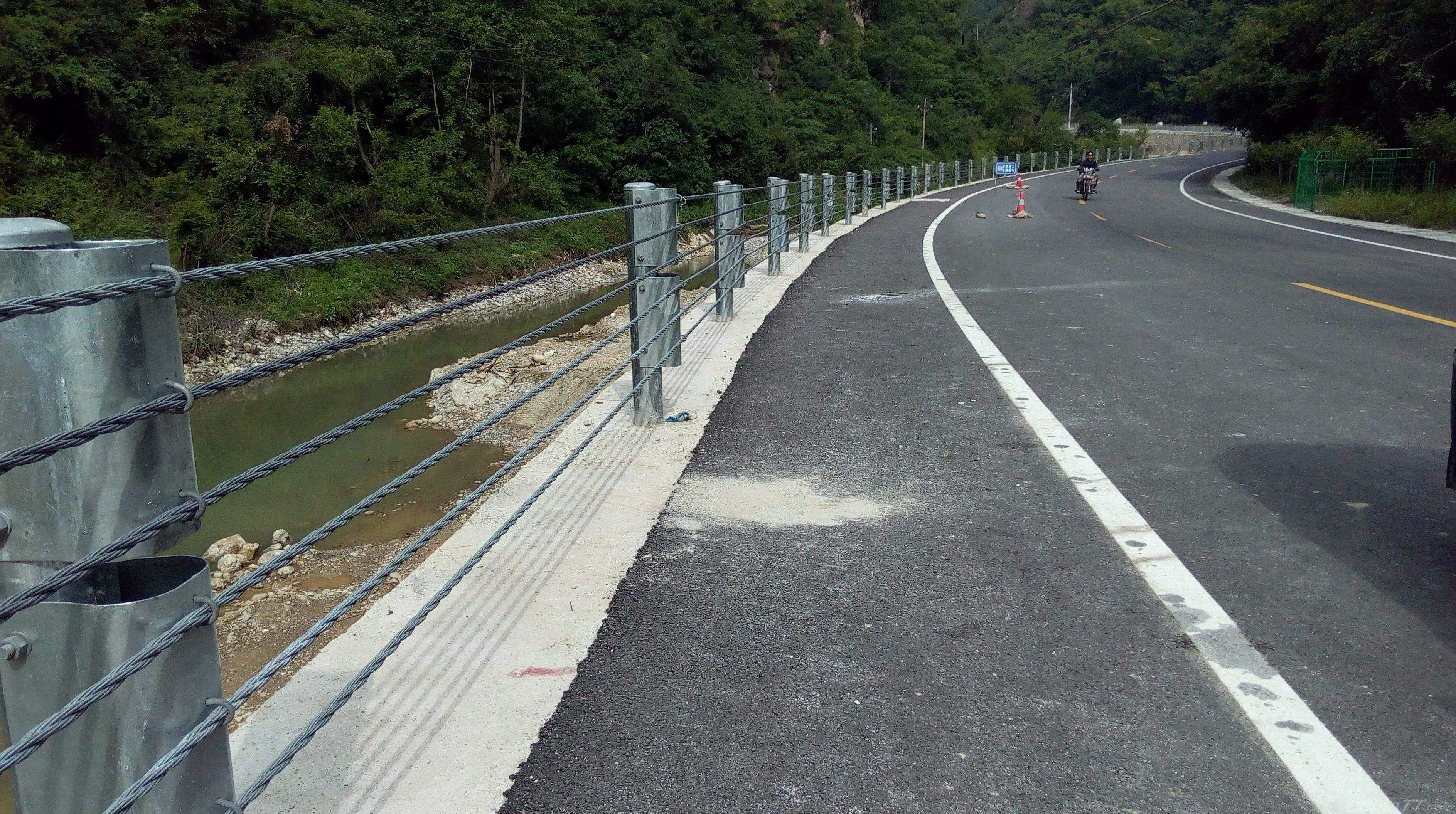
A cable barrier, sometimes referred to as guard cable or wire rope safety barrier (WRSB), is a type of roadside or median safety traffic barrier/guard rail. It consists of steel wire ropes mounted on weak posts. As is the case with any roadside barrier, its primary purpose is to prevent a vehicle from leaving the traveled way and striking a fixed object or terrain feature that is less forgiving than itself.
Because these barriers are relatively inexpensive, as opposed to concrete step barriers to install and maintain, and are very effective at capturing vehicles, their use is becoming increasingly prevalent worldwide. By far, the most popular use of the cable barrier system occurs in the medians of divided highways.
Given the opposing directions of traffic on divided highways, cross median crashes are particularly severe. While median width plays a large role in the occurrence of these crashes, increased width alone does not eliminate them and quite often, the median must be shielded with a barrier. Cable barriers provide a cost-effective solution to the shielding issue.
The system is more forgiving than traditional concrete (Jersey) barriers or steel barriers used today and remains effective when installed on sloping terrain. The flexibility of the system absorbs impact energy and dissipates it laterally, which reduces the forces transmitted to the vehicle occupants.
Although cable barriers have been used since the 1960s it was not until the mid-1990s that many departments of transportation began to deploy them with any regularity.
In many countries of the European Union these cable barriers are not allowed to be used along highways as they are perceived to be especially hazardous for motorcyclists. However, a study of motorcyclist injury rates for several types of highway barrier did not find an appreciable difference in fatal and severe injuries between cable and W-beam barriers. Both were significantly more hazardous than concrete barriers but less hazardous than none.
There are two types of cable barrier systems in use today, low-tension and high-tension. Each system has its advantages and disadvantages, but in general, a high-tension system has a higher initial cost with lower long-term maintenance costs and concerns.
During the expansion of cable barrier use throughout the 1980s and 1990s, the low-tension system was specified almost exclusively. This system is also called the “generic” system, referring to the fact that it is not exclusively manufactured by any single producer.
Due to the low tension of the system, the cables tend to lie on the ground in the event that an impact damages multiple posts. As such, there is no residual safety value within the undamaged remainder of the 2,000 ft (600 metres) installation and that entire section of barrier will remain nonfunctional until repaired.
Despite these perceived shortcomings, low-tension cable barrier, until recently, was arguably the workhorse of the industry. Thousands of miles of the generic system remain in use today in countries worldwide.
At TL-3, an 1,800 pounds (820 kg) car is crashed at 60 miles per hour (97 km/h) on an impact angle of 20°. Also at this level, a 4,400 pounds (2,000 kg) pickup truck impacts at 60 miles per hour (97 km/h) and 25°. TL-4 includes both these tests but adds a 17,600 pounds (8,000 kg) single-unit truck impacting at 50 miles per hour (80 km/h) and 25°.
All cable barrier systems available today are approved at either TL-3 or TL-4. There is a great deal of anecdotal evidence, however, that many of these systems are performing at a higher level in the field capturing vehicles as large as semi truck-trailer combinations.
Cable barrier, is intended for use on slopes with a 1:6 vertical to horizontal ratio. The 1V:6H requirement is based in both computer modeling and full-scale crash testing and represents sound theory. In practice, however, slopes as flat as 1V:6H are often the exception.
Median Cable Barriers have been studied for safety, and they are arguably effective deterrents to serious highway accidents. However, a lack of proper installation and testing has led to severe collisions and even death.Arizona, there is indication that the state government agency in charge of highway regulation failed to follow proper installation procedures.Arizona Department of Transportation was aware of cable barrier problems, and they may have also rushed installation of these barriers on state highways.
A major problem alleged, that reduces the effectiveness of cable barriers, is the installation below grade, especially around slopes or dips.Washington state, numerous letters were submitted to the state Department of Transportation complaining of cable barrier installation.
Containment or Deflection – based WRSB. Deflection aimed WRSB could be tensioned to slightly higher tension and will most probably use 4 wires (ropes). The overall length of the barrier tends to be shorter. Containment based WRSB will have wire ropes spread further apart from each other (approximately 150mm - 60mm), to increase the catchment area.
Daniello, Allison; Gabler, Hampton C. (2011). "Effect of Barrier Type on Injury Severity in Motorcycle-to-Barrier Collisions in North Carolina, Texas, and New Jersey". Transportation Research Record: Journal of the Transportation Research Board. 2262 (2262): 144–151. doi:10.3141/2262-14.
Baxter, J.R. to B. Neusch. July 2006. Gibraltar Cable Barrier on 4:1 slope @ TL-3. Federal Highway Administration. Roadside Hardware: Acceptance Letters. HSA-10 / B137C.
Top rails and midrails shall be at least one-quarter inch (0.6 cm) nominal diameter or thickness to prevent cuts and lacerations. If wire rope is used for top rails, it shall be flagged at not more than 6-foot intervals with high-visibility material.
Manila, plastic or synthetic rope being used for top rails or midrails shall be inspected as frequently as necessary to ensure that it continues to meet the strength requirements of paragraph (b)(3) of this section.
The maximum size of each safety net mesh opening shall not exceed 36 square inches (230 cm) nor be longer than 6 inches (15 cm) on any side, and the opening, measured center-to-center of mesh ropes or webbing, shall not be longer than 6 inches (15 cm). All mesh crossings shall be secured to prevent enlargement of the mesh opening.
Note: If the personal fall arrest system meets the criteria and protocols contained in Appendix C to subpart M, and if the system is being used by an employee having a combined person and tool weight of less than 310 pounds (140 kg), the system will be considered to be in compliance with the provisions of paragraph (d)(16) of this section. If the system is used by an employee having a combined tool and body weight of 310 pounds (140 kg) or more, then the employer must appropriately modify the criteria and protocols of the Appendix to provide proper protection for such heavier weights, or the system will not be deemed to be in compliance with the requirements of paragraph (d)(16) of this section.
When the path to a point of access is not in use, a rope, wire, chain, or other barricade, equivalent in strength and height to the warning line, shall be placed across the path at the point where the path intersects the warning line erected around the work area, or the path shall be offset such that a person cannot walk directly into the work area.
The rope, wire, or chain shall be rigged and supported in such a way that its lowest point (including sag) is no less than 34 inches (.9 m) from the walking/working surface and its highest point is no more than 39 inches (1.0 m) from the walking/working surface;
After being erected, with the rope, wire, or chain attached, stanchions shall be capable of resisting, without tipping over, a force of at least 16 pounds (71 N) applied horizontally against the stanchion, 30 inches (.8 m) above the walking/working surface, perpendicular to the warning line, and in the direction of the floor, roof, or platform edge;
The rope, wire, or chain shall have a minimum tensile strength of 500 pounds (2.22 kN), and after being attached to the stanchions, shall be capable of supporting, without breaking, the loads applied to the stanchions as prescribed in paragraph (f)(2)(iii) of this section; and


 8613371530291