
wire rope deflection quotation
In this article, we outline important technical topics related to wire rope. This information has been sourced from and approved by Bridon American. Use the outline to skip to specific sections:
Any assembly of steel wires spun into a helical formation, either as a strand or wire rope (when subjected to a tensile load) can extend in three separate phases, depending on the magnitude of the applied load.
At the commencement of loading a new rope, extension is created by the bedding down of the assembled wires with a corresponding reduction in overall diameter. This reduction in diameter is accommodated by a lengthening of the helical lay. When sufficiently large bearing areas have been generated on adjacent wires to withstand the circumferential compressive loads, this mechanically created extension ceases and the extension in Phase 2 commences. The Initial Extension of any rope cannot be accurately determined by calculation and has no elastic properties.
The practical value of this characteristic depends upon many factors, the most important being the type and construction of rope, the range of loads and the number and frequency of the cycles of operation. It is not possible to quote exact values for the various constructions of rope in use, but the following approximate values may be employed to give reasonably accurate results.
Following Phase 1, the rope extends in a manner which complies approximately with Hookes Law (stress is proportional to strain) until the limit of proportionality or elastic limit is reached.
It is important to note that wire ropes do not possess a well defined Young’s Modulus of Elasticity, but an ‘apparent’ Modulus of Elasticity can be determined between two fixed loads.
By using the values given, it is possible to make a reasonable estimate of elastic extension, but if greater accuracy is required, it is advisable to carry out a modulus test on an actual sample of the rope. As rope users will find it difficult to calculate the actual metallic steel area, the values can be found in the Wire Rope Users Manual or obtained from Bridon Engineering.
The permanent, non-elastic extension of the steel caused by tensile loads exceeding the yield point of the material. If the load exceeds the Limit of Proportionality, the rate of extension will accelerate as the load is increased until a loading is reached at which continuous extension will commence, causing the wire rope to fracture without any further increase of load.
The coefficient of linear expansion (∝) of steel wire rope is (6.94 x 10⁻⁶ per °F) and therefore the change in length of 1 foot of rope produced by a temperature change of t (°F) would be:
Example: What will be the total elongation of a 200 ft. length of 1-1/8″ diameter Blue Strand 6 x 41 IWRC wire rope at a tension of 20,000 Ibs. and with an increase in temperature of 20°F?
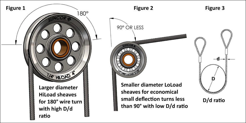
In addition to bending stresses experienced by wire ropes operating over sheaves or pulleys, ropes are also subjected to radial pressure as they make contact with the sheave. This pressure sets up shearing stresses in the wires, distorts the rope’s structure and affects the rate of wear of the sheave grooves. When a rope passes over a sheave, the load on the sheave bearing results from the tension in the rope and the angle of rope contact. It is independent of the diameter of the sheave.
Assuming that the rope is supported in a well fitting groove, then the pressure between the rope and the groove is dependent upon the rope tension and diameter, but is independent of the arc of contact.
It must be realized that this method of estimation of pressure assumes that the area of contact of the rope in the groove is on the full rope diameter, whereas in fact only the crowns of the outer wires are actually in contact with the groove. It is estimated that the local pressures at these contact points may be as high as five times those calculated. If the pressure is high, the compressive strength of the material in the groove may be insufficient to prevent excessive wear and indentation, and this in turn will damage the outer wires of the rope and effect its working life.
As with bending stresses, stresses due to radial pressure increase as the diameter of the sheave decreases. Although high bending stresses generally call for the use of flexible rope constructions having relatively small diameter outer wires, these have less ability to withstand heavy pressures than do the larger wires in the less flexible constructions. If the calculated pressures are too high for the particular material chosen for the sheaves or drums or indentations are being experienced, consideration should be given to an increase in sheave or drum diameter. Such a modification would not only reduce the groove pressure, but would also improve the fatigue life of the rope.
The pressure of the rope against the sheave also causes distortion and flattening of the rope structure. This can be controlled by using sheaves with the correct groove profile, which, for general purposes, suggests a recommended groove diameter of nominal rope diameter +6%. The profile at the bottom of the groove should be circular over an angle of approximately 120° and the angle of flare between the sides of the sheave should be approximately 52°.
Bend fatigue testing of ropes usually consists of cycling a length of rope over a sheave while the rope is under a constant tension. As part of their ongoing development program, Bridon has tested literally thousands of ropes in this manner over the years on their own in-house design bend testing equipment.
Through this work, Bridon has been able to compare the effects of rope construction, tensile strength, lay direction, sheave size, groove profile and tensile loading on bend fatigue performance under ideal operating conditions. At the same time it has been possible to compare rope life to discard criteria (e.g. as laid down in ISO 4309) with that to complete failure of the rope, i.e. to the point where the rope has been unable to sustain the load any longer. As part of the exercise, it has also been possible to establish the residual breaking strength of the rope at discard level of deterioration.
What needs to be recognized, however, is that very few ropes operate under these controlled operating conditions, making it very difficult to use this base information when attempting to predict rope life under other conditions. Other influencing factors, such as dynamic loading, differential loads in the cycle, fleet angle, reeving arrangement, type of spooling on the drum, change in rope direction, sheave alignment, sheave size and groove profile, can have an equally dramatic effect on rope performance.
If designers or operators of equipment are seeking optimum rope performance or regard bending fatigue life as a key factor in the operation of equipment, such information can be provided by Bridon for guidance purposes.
Wire ropes are manufactured slightly larger than the nominal diameter. The maximum allowable oversize tolerances provided by industry standards are shown in the following table:
Under certain circumstances it may be necessary to use a swivel in a lifting system to prevent rotation of the load. This is typically done for employee safety considerations. It is possible however, that the use of a swivel will have an adverse affect on rope performance and may, in some cases, damage the wire rope.
The type of swivel that causes the most concern from the standpoint of the wire rope is the independent anti-friction swivel that attaches directly to the rope. The purpose of using a swivel in a lifting system is to prevent rotation of the load. This then allows the wire rope to rotate. Excessive rope rotation can damage a wire rope.
To assist in determining whether or not a swivel should be used in the lifting system, the following recommendations should be considered. It must also be recognized that the rotation characteristics of different types and constructions of wire rope vary considerably. The following types and constructions of wire rope are grouped according to their rotation characteristics.
These rope constructions will rotate excessively with one end free to rotate, and the rope will unlay and distort and be easily damaged with a loss of rope breaking force.Blue Strand 6 x 19 and 6 x 36 Class Lang Lay
Wire rope constructions having high rotation characteristics when used in single part reeving may require a swivel in the system to prevent rotation in certain operating conditions. However, this should be done only when employee safety is the issue.
These rope constructions, when used in a reeving system with one end free to rotate, will have a high level of rotation. This will cause the rope to unlay and, to some degree, distortion of the rope will occur.Blue Strand 6 x 19 and 6 x 36—Class Regular Lay
The ropes in this Group are designed with an inner rope that is laid in the opposite direction to the outer strands to provide a medium resistance to rotation. Ropes with medium rotation characteristics are used with a swivel in single part reeving applications. However, a swivel is not recommended for multiple part hoisting applications or in any application where the swivel is not necessary for safety reasons. If it is necessary to use a swivel, the rope must be operating at a design factor of 5 or greater, must not be shock loaded and must be inspected daily by a qualified person for distortion.
It should be noted that if a swivel is used on conjunction with Group 3a ropes, rope service life might be reduced due to increased internal wear between the outer strands and the inner rope.Group 3aEndurance 8RR Rotation Resistant
Wire ropes having low rotation characteristics used in either single or multiple part reeving may be used with a swivel. The reason for this is that the ropes will exhibit very little, if any, rotation when used at the proper design factor. Application parameters, such as a fleet angle, may induce turn into a wire rope that can be relieved by the use of a swivel. However, if the application does not induce any turn into the rope, or if a swivel is not beneficial to the performance of the rope, the swivel may not be necessary.Endurance 35 LS
If the drum incorporates helical grooving, the helix angle of the groove needs to be added or subtracted from the fleet angle as described above to determine the actual fleet angle experienced by the rope.
When spooling rope onto a drum, it is generally recommended that the fleet angle is limited to between 0.5° and 2.5°. If the fleet angle is too small, i.e. less than 0.5°, the rope will tend to pile up at the drum flange and fail to return across the drum. In this situation, the problem may be alleviated by introducing a ‘kicker’ device or by increasing the fleet angle through the introduction of a sheave or spooling mechanism.
If the rope is allowed to pile up, it will eventually roll away from the flange, creating a shock load in both the rope and the structure of the mechanism, an undesirable and unsafe operating condition.
Excessively high fleet angles will return the rope across the drum prematurely, creating gaps between wraps of rope close to the flanges, as well as increasing the pressure on the rope at the cross-over positions.
Even where helical grooving is provided, large fleet angles will inevitably result in localized areas of mechanical damage as the wires ‘pluck’ against each other. This is often referred to as ‘interference’, but the amount can be reduced by selecting a Langs lay rope if the reeving allows. The “interference” effect can also be reduced by employing a Dyform rope, which offers a much smoother exterior surface than conventional rope constructions.
Where a fleet angle exists as the rope enters a sheave, it initially makes contact with the sheave flange. As the rope continues to pass through the sheave it moves down the flange until it sits in the bottom of the groove. In doing so, even when under tension, the rope will actually roll, as well as slide. As a result of the rolling action, the rope is twisted, i.e. turn is induced into or out of the rope, either shortening or lengthening the lay length of the outer layer of strands. As the fleet angle increases, so does the amount of twist.
To reduce the amount of twist to an acceptable level, the fleet angle should be limited to 2.5° for grooved drums and 1.5° for plain drums and when using Rotation Resistant, ropes the fleet angle should be limited to 1.5°.
However, for some crane and hoist applications, it is recognized that for practical reasons. It is not always possible to comply with these general recommendations, in which case, the rope life could be affected.
The problem of torsional instability in crane hoist ropes would not exist if the ropes could be perfectly torque balanced under load. The torque generated in a wire rope under load is usually directly related to the applied load by a constant ‘torque factor’. For a given rope construction, the torque factor can be expressed as a proportion of the rope diameter and this has been done below.
Variation with rope construction is relatively small and hence the scope for dramatically changing the stability of a hoisting system is limited. Nevertheless, the choice of the correct rope can have a deciding influence, especially in systems which are operating close to the critical limit. It should be noted that the rope torque referred to here is purely that due to tensile loading. No account is taken of the possible residual torque due, for example, to rope manufacture or installation procedures.
Torsional Stability and the Cabling Graph are two methods which can be used to determine torsional stability or the tendency of the rope to cable. The torque factors quoted are approximate maximum values for the particular constructions. To calculate the torque value for a particular rope size, multiply by the nominal rope diameter.
The torsional characteristics of wire rope will have the effect of causing angular displacement of a sheave block when used in multi-fall reeving arrangements. The formula below gives a good approximation under such arrangements.
The preceding equations are all relative to a simple two part reeving. For more complex systems, a similar approach may be used if account is taken of the different spacings of the ropes.
The equations assume that rope is torque-free in the noload condition, therefore, induced torque during or immediately after installation will adversely influence the calculated effect.
The above data assumes a constant torque value which is a valid assumption for a new rope. Wear and usage can have a significant effect on the torque value, but practical work shows that under such circumstances, the torque value will diminish, thus improving the stability of the arrangement. Some arrangements may be of such complexity that the evaluation demands a computer study.
Assuming a pedestal crane working on two falls is roped with 20mm diameter DYFORM 34LR and the bottom block carries a sheave of 360mm diameter with the falls parallel:
If the rope is new (worst condition) and no account is taken of block weight and friction then angular displacement for a height of lift of 30 meters is given by:
Field research jointly conducted by the Wire Rope Technical Board and the Power Crane and Shovel Association has shown that cabling of the rope parts in a multiple part reeved hoisting arrangement is controlled by several factors. The following calculations and graphs can be used to determine when and if cabling will occur on multiple part reeved hoisting arrangements.
Various constructions of rope shown on the graph indicate the limited conditions for torsional stability with the angular displacement of the hoist block to a maximum of 90 degrees. When the operating conditions for a particular installation give a resultant above the appropriate band, then cabling of the falls will most likely occur. If the operating conditions give a resultant below any particular band, the cabling of the falls will most likely not occur. If the operating conditions for any particular installation fall within the band, cabling is unpredictable.

Like all industrial equipment, aircraft cables and wire ropes wear while in service, and will require replacement. Though the cycle life of each cable varies based on construction and application, factors such as load and pulley condition can actually reduce this lifespan by triggering wire breaks. Not all wire breaks look the same, and understanding these differences can help detect issues in your system before they damage additional cables, or put human lives in danger. Here is a quick guide to help you understand where wire breaks occur (crowns vs. valleys), and three common examples of wire breaks (tension, fatigue, and abrasion).
Wire breaks typically occur in two different locations on the outside of wire rope or aircraft cable. The first location is on the crowns of the strands, which are the highest points with the most surface area exposure. The second location is the valleys, or the spaces between the strands. Though crown breaks typically result from normal wear and tear, valley breaks are more suspicious and may indicate issues with the pulley system or wire rope itself.
Wires that have been worn to a knife-edge thinness are characteristic of abrasion breaks. Abrasion can occur from a number of different sources, but sheaves are the most common. Remember to check sheaves for signs of wear, damage, or deformity and replace as necessary.
If you notice one end of a broken wire is cupped, and the other end resembles a cone, your wire rope likely experienced a tension break. Tension breaks result from excessive loading, causing the wires to stretch beyond their limits until they snap. Once one wire break appears, others will continue to occur if the cable is not addressed.
Once you have replaced your damaged pulleys, or removed sharp obstructions in your system, begin your quote for brand new wire rope at https://strandcore.com/contact/. Our wire rope craftsmen can help you select the ideal wire rope for your application, and oftentimes provide a better solution for your existing setup. Browse our selection ofwire rope and aircraft cableonline, and do not hesitate to contact our sales team at sales@sanlo.com if you have any questions.

New here? Try reading these, they might help FAQ731-376: Eng-Tips.com Forum Policies http://eng-tips.com/market.cfm? RE: Increased tension in wire rope
New here? Try reading these, they might help FAQ731-376: Eng-Tips.com Forum Policies http://eng-tips.com/market.cfm? RE: Increased tension in wire rope
Handleman... if I understand the problem, it"s not so trivial...it"s deceptive. The cable has an initial load of 100 Kg and an initial sag; there is no reference to the cable weight or material (assumed to be steel and fy and Es not known) and a length of 6.5 m. The 8.5 Kg load applied to the center causes it to deflect 150mm. I"m not sure how that is arrived at, by measurement? In a pinch, you can establish the dia of the cable from the above info, but, it"s very complicated. With a horizontal (nearly) cable, any load applied at mid span increases the tension substantially and as it deflects this tension is relieved a bit. If at the end of the day, the total deflection is 150 mm it is a difficult solution. It could be that the weight of the cable approaches, or exceeds the weight in the middle and the weight of the cable cannot be eliminated. Definitely not a simple question problem.
OP already stated that the measured deflection due to sag is 2mm. Compared with the 150mm measured deflection under 8.5KGF load, the sag is negligible.
Again, this is statics. It is true. Therefore, something is incorrect with the OP"s setup. Let"s examine the likely culprits. 6.5mm span? Not so likely. Easy to measure. Same with deflection amount and actual mass of applied weight. That leaves tension. OP has already stated that tensometer accuracy is questionable, because the measured increase was "5-10kgf". Therefore, the obvious conclusion is that the initial 100kgf measurement is inaccurate.
The OP specifically stated point load at the center. This is most certainly NOT a catenary. Catenary is the shape created by the distributed weight load of a hanging rope/chain due to its own weight. OP specifically stated that the measured sag (which is a catenary) before weight was added is 2mm. A 2mm catenary over 6.5m. This is pretty negligible for our purposes, as compared with the 150mm deflection induced by the weight.
But, just for fun, we can find the approximate weight of the 6.5m rope if it makes us feel any better. We"re already doubting the initial tension statement, but, giving a window of 90 to 110kgf actual tension, our window for total mass of the 6.5m rope is somewhere between 0.23kg and 0.28kg. (verification left as an exercise) Again, insignificant compared to the 8.5kg weight hanging from the center.
So, given that we know the final tension, how can we find the initial tension? Again, as rb mentioned, it has everything to do with the strain of the rope.
Let"s consider what we know to be true: 8.5kg weight hanging at 150mm deflection from a 6.5m span. Now, imagine 2 different ropes. First, consider a theoretically perfectly zero stretch rope. What happens when you remove the weight? What is the tension? Almost nothing. It will fall into a loose catenary with the same length as the 2 hypotenii. Interestingly enough, since we already calculated the weight of the actual rope is apx 0.25kgf, we can calculate the catenary sag amount as apx 130mm, and the cable tension somewhere around 1.6 kgf for this completely non-stretch rope (another exercise for the reader). Now let"s consider a rubber band. It"s a really long rubber band. and it has a "spring constant", if you will, of 1kgf/mm. When you remove the center weight, the band contracts and goes horizontal (ignoring its mass). We can easily calculate the length difference between the hypotenii and the horizontal as apx. 7mm. Since the spring constant is 1kgf/mm, the pre-weight tension is calculated to be 92kgf-7kgf=85kgf. What if the rubber band is a bit stretchier? Like 0.1kgf/mm? Then the initial tension would be only 92-70=22kgf.
Of course, as I mentioned earlier this all assumes perfect rigidity from the entire system, such that all of the geometry change between the 2mm catenary and the 150mm deflection is due to stretch of the rope. If your stand or anchors are deflecting, or the tensometer somehow has a not-insignificant spring rate, all bets are off.
The tensiometer probably has a lot of inherent error in it that can"t give a reliable reading with the initial tension and added tension, it provides some solid confusion. Much better would be a spring scale on one end. RE: Increased tension in wire rope
I think that the OP was badly stated "The wire rope is 6.5m in length and prestressed to 100Kgs a load of 8.5kgs is applied to the center...." There should have been a period after the 100Kgs then a different picture presents itself as "The wire rope is 6.5m in length and prestressed to 100Kgs. A load of 8.5kgs is applied to the center..." . The 100 kgs prestress is to stretch the rope only. Afterward the 8 kgs is applied in a cable that is inextensible. The cable, first is under gravity acting as a catenary and secondly under the point load of 8Kgs which can be solved by vectors as pointed above. The catenary evalustion may not be necessary depending of the unit weight of the cable. For a reference into solving this type of problem, here is the title and author as I don"t have the link "; I don"t have the link but here is the thesis and its author "ON SHAPE CONTROL OF CABLES UNDER VERTICAL STATIC LOADS-DANIEL PAPINI". Page 61 is the reference needed. RE: Increased tension in wire rope
Ash. On my web site (http://rmniall.com) you will find a free downloadable spreadsheet that gives a rigorous analysis for the problem of a (single) point load applied to a cable. The cable can be inclined from horizontal, the load can be inclined from vertical, and the cable can be extensible. RE: Increased tension in wire rope
While simple statics reasonably gives 92 kg tension in the rope, a basic assumption of this is that the angle of the rope at the point load is defined by the rise and the run, and neglects any curvature of the rope, which we know exists.
Taking the angle as asin (W/2T) and T as 105kgf, I get 2.3*, which is a hair less than the 2.5* stated above. I"m happy with that. RE: Increased tension in wire rope
Moon161. "No dice"? I"m always looking for ways to improve my spreadsheets, so if you can tell me what particular dice my cable spreadsheet lacks I might be able to accommodate whatever it is you are looking for. Contact via the e-mail address in the spreadsheet and on my web site would be best. RE: Increased tension in wire rope
This is similar (equi-anglular) to the displacement triangle so displacement = 4.25/110 x 3250 = 125.6 mm. This is slightly less than the measured displacement (150mm) because the rope has some bending stiffness and the centre section of the rope acts like a beam.
Most errors with the spreadsheet went away when I extracted the .xls from the zip to a folder instead of opening from the .zip file. RE: Increased tension in wire rope
Do you need to use trig tables and introduce rounding errors? Also not sure why you have used tan and asin for similar triangles. Again I guess you are assuming the supports are rigid and the cable has stretched? I am still surprised there is 5% difference in our deflection result (126 vs 132mm).
But the only way I can get the geometry to work (150 mm deflection at center after a 8.5 Kg weight is applied at the center) is if the tension is applied by a 200 Kg weight pulling the wire rope (cable) over a pulley. The minute extra expansion of the stretch of the cable cannot the whole length long enough to create that 2.64 degree angle from the straight case. The total wire length between two points 6500 mm long with a 150 mm vertical is 6506.9 mm. You"d be claiming the cable stretched 7 mm.
Now, the "cable" might stretch that much by the slipping and "unkinking" of the individual wire strands against each other, but the "metal" itself would not stretch that much if it were a solid cylinder of uniform cross-section.
And the orignal 200 Kg weight should remove much of that "mechanical" wire fiber unkinking and slip from the initial "unstressed" condition to its t=0 straight length before putting the 8.5 Kg weight on. RE: Increased tension in wire rope
You"d be claiming the cable stretched 7 mm. Now, the "cable" might stretch that much by the slipping and "unkinking" of the individual wire strands against each other, but the "metal" itself would not stretch that much if it were a solid cylinder of uniform cross-section.
Why not? The cable is small. As handleman points out, the total mass of the 6.5m rope is only ~.25kg. My quick calculation shows that 7mm is plausible.

Sta-Lok stocks a comprehensive range of stainless steel grade 1.4401 (AISI 316) wire rope on 100,200 and 300-metre reels. Conforming to international standards, all wire is certified and fully traceable, in line with our quality systems and ISO 9001 accreditation. Learn how to choose the right wire rope here: Wire Rope Properties.

Wire rope maintenance is a vital part of crane safety, performance and longevity. Hundreds of components work together to lift and suspend huge amounts of weight, so keeping this thin band of strength in proper condition is essential. American Cranes & Transport (ACT) Magazine recently published a summary of what steps should be taken to keep wire rope operating smoothly.
Sheaves need to be able to move freely and without wobbling. This prevents vibration which can cause fatigue to the wire rope. Additionally, the groove should be one percent larger than the maximum rope diameter including its allowable tolerance. Sheaves that are worn or too small can cause forced twist deformation, while tolerances that are too large can cause damage from lack of support. Rollers should also be inspected regularly to be sure they’re free of corrugation and wear, and that the bearings operate smoothly.
Bending a wire rope causes individual strands to rub against each other, and that rope running through a sheave is subject to wear. A wire rope that is not properly lubricated will cause friction and a drastic shortening of its lifespan. In general, ropes should have a thin coat of maintenance lubricant applied every six to 12 months. Its properties must be compatible with the original lubricant and designed specifically for wire rope. It must be able to penetrate and evenly coat all the strands of wire as opposed to just remaining on the outermost surface.
Wire rope should be sufficiently tensioned on the drum during installation, and a good amount of tension is five to ten percent of the working load limit. This causes the wire to tighten and resist crushing from the incoming loaded rope. Applying tension is not just a one-time event as unused wire slowly loosens and should have tension reapplied during crane maintenance.
Another suggestion to extend the rope’s lifetime involves cutting a length equal to 1-1/4 drum wraps from the drum end, which will reposition the wear points. This should be done three or more times during the rope’s lifespan, and before these sections show more wear than the rest of the rope.
These points just scratch the surface of maintaining the safety and integrity of a crane’s wire rope. Read the entire article at American Cranes & Transport’s website by clicking here. Images above courtesy of ACT.
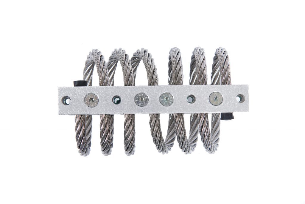
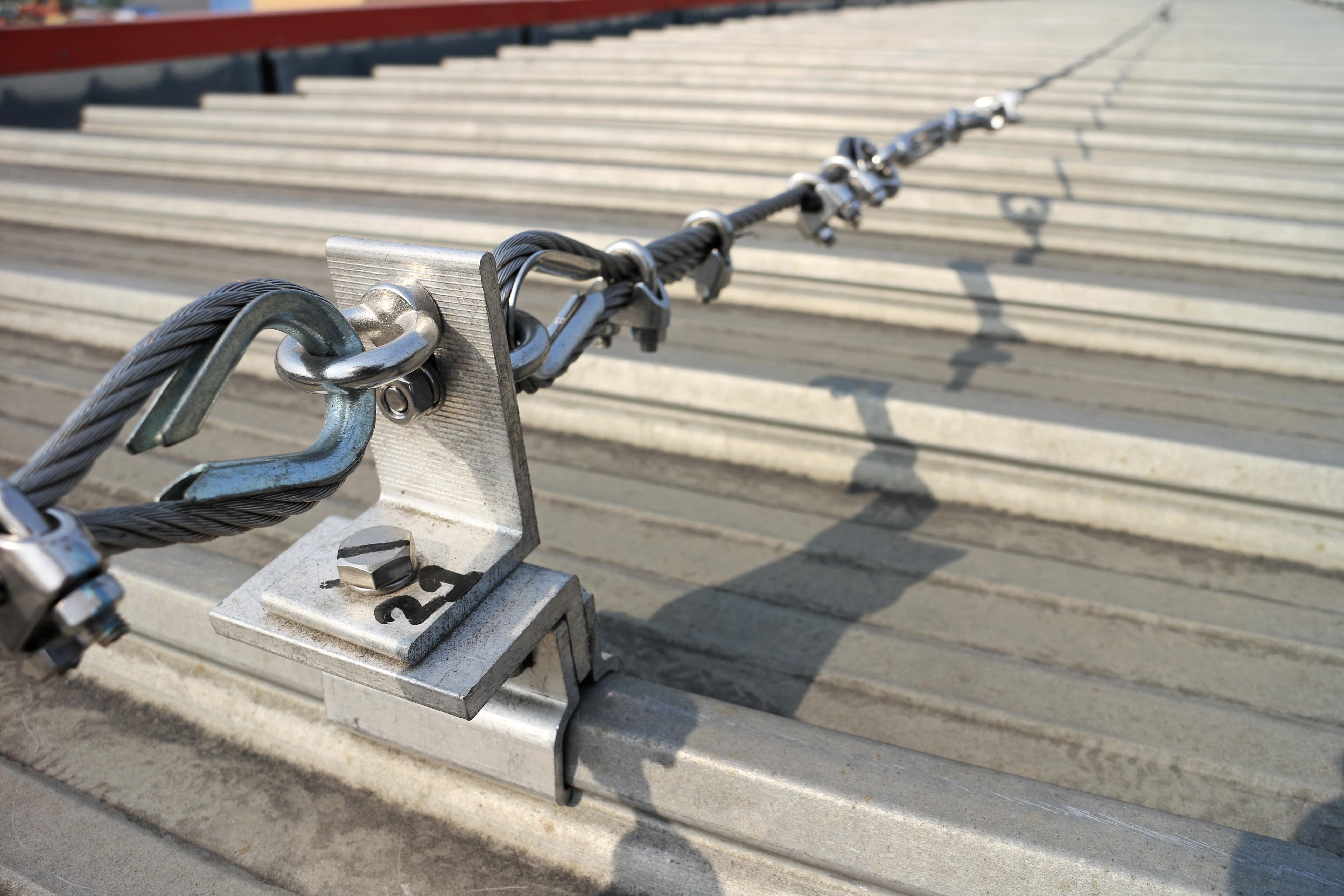
All ductwork and equipment shall be supported using wire rope cable terminated by Cable Locks. All Cable Locks shall have an Ultimate Breaking Strength (U.B.S.) of at least 5 times the wire rope published Working Load Limit (W.L.L.). All wire rope shall have a U.B.S. of 5 times the published W.L.L. Wire ropes shall be of the size and spaced per manufacturers printed specifications. Wire Rope and Cable for Rectangular Duct, Round Duct, Spiral Pipe.
Wire rope manufacturers produce their products in order to provide a high load capacity, versatile alternative to weaker ropes like manila rope or hemp rope. Wire rope products are used for a wide variety of motion transmission applications, among them: lifting, baling, tie down, hoisting, hauling, towing, mooring, anchoring, rigging, cargo control, guidance and counterbalance. They can also be used as railing, fencing and guardrailing.
Wire rope is a must-have for many heavy duty industrial applications. From mining to forestry to marine and beyond, there’s wire rope for almost every job. Some of the many industries in which wire rope is popular include: construction, agriculture, marine, industrial manufacturing, fitness, sports and recreation (plastic coated cables for outdoor playground equipment and sports equipment), electronics, theater (black powder coated cables for stage rigging), mining, gas and oil, transportation, security, healthcare and consumer goods.
Wire rope as we know it was invented just under 200 years ago, between 1831 and 1834. At that time, the goal was to create a rope strong enough to support work in the mines of the Harz Mountains. Invented by Wilhelm Albert, a German mining engineer, this wire rope consisted on four three-stranded wires. It was much stronger than older rope varieties, such as manila rope, hemp rope and metal chain rope.
While studying at Freiburg School of Mines, a man named L.D.B. Gordon visited the mines in the Harz Mountains, where he met Albert. After he left, Gordon wrote to his friend Robert Stirling Newall, urging him to create a machine for manufacturing wire ropes. Newall, of Dundee, Scotland, did just that, designing a wire rope machine that made wire ropes with four strands, consisting of four wires each. After Gordon returned to Dundee, he and Newall, along with Charles Liddell, formed R.S. Newall and Company. In 1840, Newall received a patent for “certain improvements in wire rope and the machinery for making such rope.”
In 1841, an American manufacturer named John A. Roebling began producing wire rope for suspension bridges. Soon after, another set of Americans, Josiah White and Erskine Hazard, started incorporating wire rope into coal mining and railroad projects, forming Lehigh Coal & Navigation Company (LC&N Co.). In 1848, wire rope from their wire rope factory in Mauch Chunk, Pennsylvania provided the lift cables needed to complete the Ashley Planes Project. This project sought to improve the performance and appearance of the freight railroad that ran through Ashley, Pennsylvania, by adding lift cables. This increased tourism and increased the railroad’s coal capacity. Before, cars took almost four hours to return; after, they took less than 20 minutes.
Wire rope likewise changed the landscape (again) in Germany, in 1874, when an engineering firm called Adolf Bleichert & Co. used wire rope to build Bi-cable aerial tramways. These allowed them to mine the Ruhr Valley. Several years later, they also used wire rope to build tramways for the German Imperial Army and the Wehrmacht. These tramways were wildly successful, opening up roads in Germany and all over Europe and the USA.
Since the 1800s, manufacturers and engineers have found ways to improve wire rope, through stronger materials and material treatments, such as galvanization, and different rope configurations. Today, wire rope makes possible many heavy industrial processes. It has become a necessity of the modern world.
Strands are made by tightly twisting or braiding individual wire together. One strand could have anywhere between two and several dozen wire filaments depending on the necessary strength, flexibility, and weight capacity.
One of the most dynamic elements of wire cables is the inner core. The strands are wrapped around the core, and it can be made of different metals, fibers, or even impregnated fiber materials. For heavy applications, cores are often made of a different strand of wire called an independent wire rope core (IWRC). An IWRC has a considerable amount of flexibility and it is still very strong. In fact, at least 7.5% of the strength increase in a wire rope can be attributed to an IWRC.
While they sometimes use other metals, like aluminum, nickel, copper, titanium, and even bronze for some applications, manufacturers primarily produce wire rope from steel. This is because steel is very strong and stretchable. Among the most common types they use are: galvanized wire, bright wire, stainless steel and cold drawn steel.
Of the wire rope steels, cold drawn carbon steel wire is most popular, although stainless steel wire rope is sometimes employed as well. Stainless steel rope is most popular for its anti-corrosive properties. Bright wire rope, a type of ungalvanized steel wire rope, is also popular. For added strength and durability, galvanized steel wire rope/galvanized steel cables are a very popular choice. Galvanized aircraft cable, for example, is always a must in aerospace.
When choosing or designing a custom wire rope for your application, suppliers consider factors such as: the environment in which the rope will function, required rust resistance, required flexibility, temperature resistance, required breaking strength and wire rope diameter. To accommodate your needs, manufacturers can do special things like: make your rope rotation resistant, color code your rope, or add a corrosion resistant coating. For instance, sometimes they specially treat and coat a cable with plastic or some other compound for added protection. This is particularly important to prevent fraying if the wire rope is often in motion on a pulley.
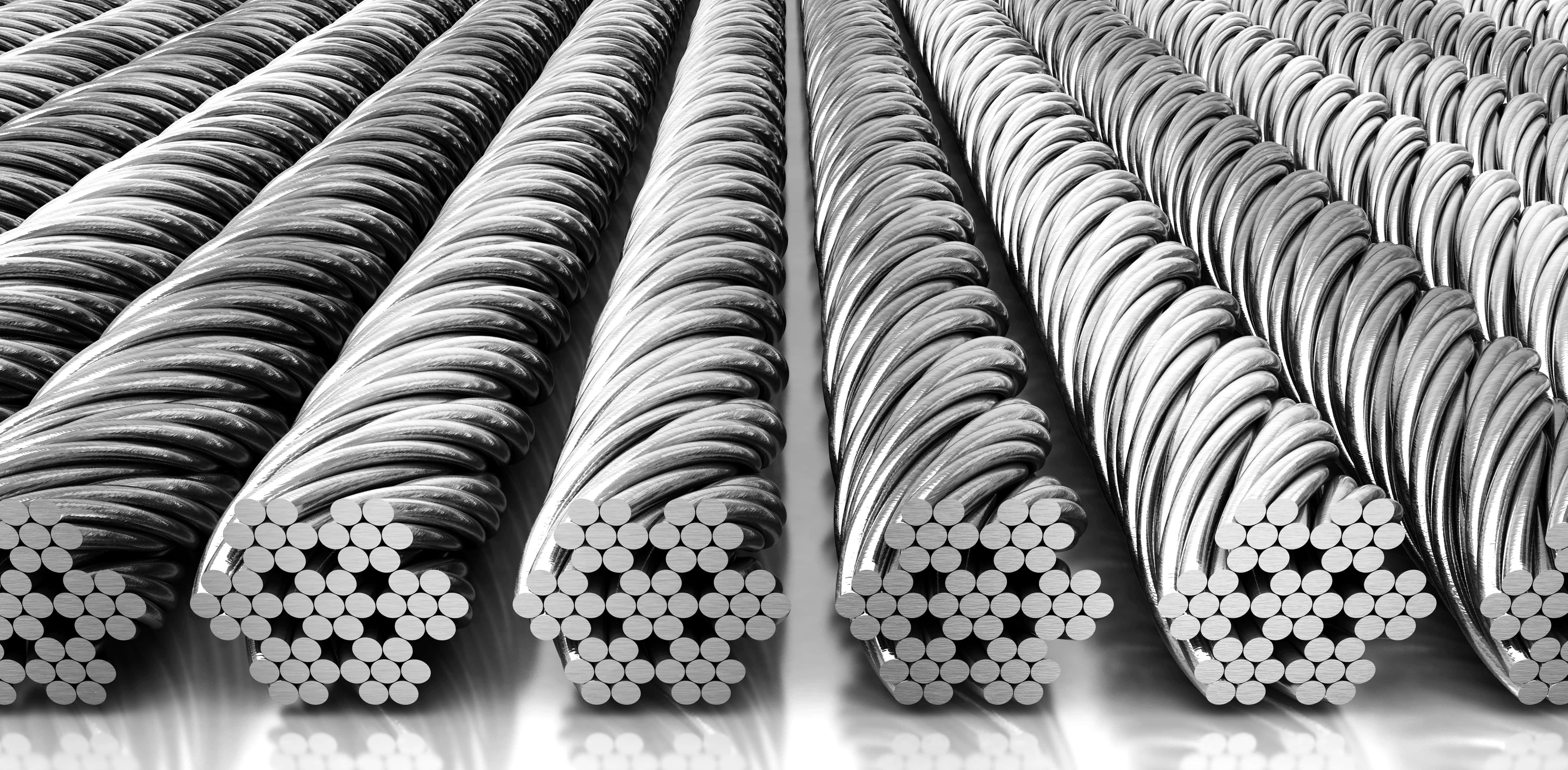
Manufacturers and distributors identify the differences in wire cable by listing the number of strands and the amount of wires per strand so that anyone that orders understand the strength of the cable. Sometimes they are also categorized by their length or pitch. Common examples of this include: 6 x 19, 6 x 25, 19 x 7, 7 x 19, 7 x 7, 6 x 26 and 6 x 36.
More complex wire rope identification codes connote information like core type, weight limit and more. Any additional hardware like connectors, fasteners, pulleys and fittings are usually listed in the same area to show varying strengths and degrees of fray prevention.
Cable wire rope is a heavy-duty wire rope. To give it its high strength, manufacturers construct it using several individual filaments that are twisted in strands and helically wrapped around the core. A very common example of cable wire rope is steel cable.
Spiral rope is made up an assemblage of wires with round or curved strands. The assemblage features at least one outer layer cord pointed in the opposite direction of the wire. The big advantage of spiral ropes is the fact that they block moisture, water and pollutants from entering the interior of the rope.
Similarly, stranded rope steel wire is made up of an assemblage of spirally wound strands. Unlike spiral rope, though, its wire patterns have crisscrossing layers. These layers create an exceptionally strong rope. Stranded rope may have one of three core material types: wire rope, wire strand or fiber.
Wire rope chain, like all chains, is made up of a series of links. Because it is not solid, wire rope chain is quite flexible. At the same time, it is prone to mechanical failure.
Wire rope slings are made from improved plow wire steel, a strong steel wire that offers superior return loop slings and better security. The plow wire steel also shields rope at its connection points, which extends its working life. Wire rope slings, in general, provide their applications with increased safety, capacity and performance. Wire rope sling is a rope category that encompasses a wide range of sub-products, such as permaloc rope sling, permaloc bridle slings and endless slings. These and other wire rope slings may be accompanied by a wide variety of sling terminations, such as thimbles, chokers and hooks.
Wire rope offers its user many advantages. First, design of even distribution of weight among strands makes it ideal for lifting extremely heavy loads. Second, wire rope is extremely durable and, when matched properly to the application, can withstand great stress and elements like corrosion and abrasion. In addition, it is very versatile. Its many iterations and the ways in which the rope can treated means that users can get rope custom fit for virtually any application.
Depending on the type of wire rope with which you are working and your application, you may want to invest in different accessories. Among these accessories are: wire rope clips, steel carabiners, fittings, fasteners and connections.
To ensure that your wire rope quality remains high, you must regularly inspect them for wear and degradation. The right wire rope should be selected for a particular use. Watch out for performance-impacting damage like: rust, fraying and kinks. To make sure that they stay in tip-top shape, you should also clean and lubricate them as needed. Check for this need as a part of your regular inspection.
Rope care is about more than inspection. It’s also about making an effort to use and store them properly every time you use them. For example, never exceed your rope’s rated load and breaking strength. Doing so will not only cause the weakening of your cable, but it may even cause immediate breakage. In addition, always store your wire rope cable in a dry and warm area, away from those elements that could cause premature rusting or other damage. Finally, always carefully wind your wire rope when you’re done with it, so as to avoid kinks. If you follow all these tips and treat your wire rope assemblies well, they will reward you with a long and productive service life.
Always make sure that you purchase wire rope that matches your industry and regional standards. Some of the most widely referenced standards organizations for wire rope include: ISO, ASTM International and OSHA. Talk over your specifications and application with your wire rope supplier to figure out what’s best for you.
If you’re in the market for a wire rope or a wire rope assembly, the best way to know you’re getting something that will both perform well and be safe if by working with a vetted professional. Find one among the list we’ve provided on this page. Check out their profiles to get an idea of the services and products they offer. Pick out three or four to whom you’d like to speak, and reach out. Talk to them about your specifications, standard requirements and budget. Ask about lead times and delivery options. Once you’ve spoken with all of them, compare and contrast their answers. You’ll know you’ve found the one when you talk to a wire rope company that is willing to go above and beyond for your satisfaction.

The cable on a crane moves through a series of motorized pulleys that are controlled by the crane operator to raise and lower items. For safety reasons, a crane usually has several wire rope cables that are attached to the object being lifted. This helps to prevent putting too much strain on a single cable.
To create wire rope cable, manufacturers begin with long strips of high tensile strength metal that are tightly woven together into strands. A large majority of wire rope cables are constructed using steel due to its durability and strength. Several strands are then spun and pressed tightly together into a helix using a machine.
The newly created wire rope cable is then rolled up onto a spool and shipped out, or it is rolled up onto a pulley to be used with a brand new piece of heavy equipment.
Stationary ropes bear tensile forces and are loaded with fluctuating levels of stress. These are the types of cables that would be found on a suspension bridge.
Finally, wire rope slings (also called stranded ropes) are used to harness all kinds of goods. These are bent over sharp edges of goods to hold them in place.
The MASH compliant O-Post Wire Rope Barrier System (WRSF) offers a patented interweaving of the wire ropes to contain & redirect errant vehicles. This unique design helps to prevent vehicles from crossing the barrier or deflecting back into the traffic flow. The O-Post WRSF is designed to absorb the energy of an impact, minimizing injury to passengers and damage to vehicles.
The load which a new wire rope may handle under given operating conditions and at an assumed design factor. A design factor of five is chosen most frequently for wire rope. (Operating loads not to exceed 20% of catalog breaking strength). Operating loads may have to be reduced when life, limb, or valuable property are at risk, or other than new wire rope is used. A design factor of 10 is usually chosen when wire rope is used to carry personnel. (Operating loads not to exceed 10% of catalog breaking strength). Responsibility for choosing a design factor with the user.
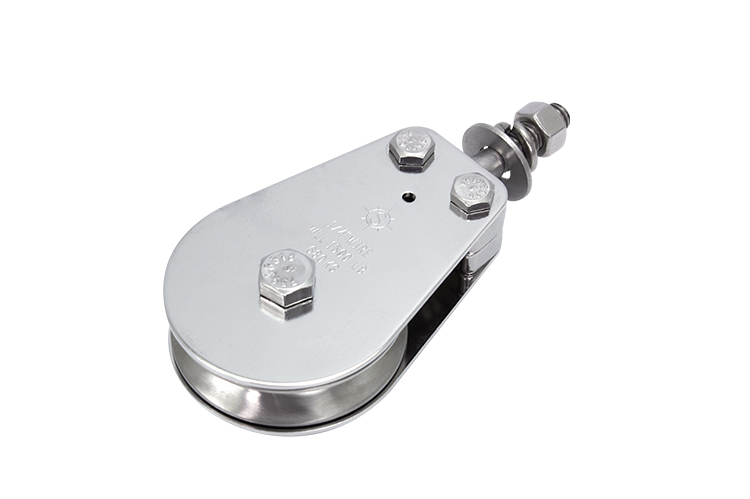
Rope sockets, thimbles, sleeves, hooks, links, shackles, sheaves, blocks, etc., must match in size, materials and strength, to provide adequate safety protection. Proper installation is crucial for maximum efficiency and safety.
Wire rope is constructed of multiple strands of wire that are twisted and braided together to form a spiral design or helix. Once the separate wires are shaped into a solid form, they become a single wire with greater strength because the individual wires equalize pressure and have greater flexibility than the individual strands.
To further enhance the strength of wire ropes, they are grouped and wound together to produce cables, which adds to their usefulness as a means of support, ability to lift, and give structural stability.
A key factor in wire rope is the lay of the strands, which can be regular or lang. With regular lay, or right and ordinary lay, the strands are wound from left to right with the wires laid in the opposite direction of the lay of the strands. With lang lay, the wires are wound in the same direction.
The structure and design of wire rope produces a final product that has superior strength, excellent strength flexibility, and the ability to handle constant bending stress as well as being weather resistant.
Wire rope is one of those products that has found a place in a wide variety of industries since it can be adapted and shaped to fit several applications. It can be found as a tow cable for boats and airplanes or in the movie industry as a harness for stunt artists. The varied uses of wire rope have made it an essential part of operations that require a rope with strength, endurance, and flexibility.
In the aerospace industry, wire ropes, or Bowden cables, connect pedals and levers in the airplane cockpit to send power to aircraft systems to control the airplane. The things that are controlled by wire ropes are propeller pitch, cowl flaps, and throttle. Wire ropes on aircraft are insulated to avoid vibrations.
Wire rope is extensively used in the auto industry for a wide variety of applications due to its versatility and strength. It is used for raising windows and opening and closing sunroofs. Other uses include steering wheels, cables, exhausts, springs, sunroofs, doors, and seat components. In the manufacturing process, wire rope is used to hoist vehicles, move large body parts, and on hoists and cranes.
The construction industry has a greatest reliance on wire rope because of the need to lift and lower heavy loads. Wire rope used in construction must have extremely high strength and exceptional performance for safety reasons and efficiency. Larger versions of wire rope are used for suspension bridges and supporting concrete columns.
The main use of wire rope in food processing is for lifting, moving loads, and other heavy tasks. Finished products or raw materials require being moved in storage units and processing centers. The strength and endurance of wire rope makes it possible to move these materials. Wire rope for food processing must be able to withstand regular chemical cleaning.
As with other industries, the oil and gas industry needs strong and reliable equipment for moving heavy equipment. In ocean drilling, machinery is dropped into the ocean using wire rope to securely hold devices to be dropped to extreme depths. Wire ropes are designed to withstand the extreme pressure and stress required. A further use of wire ropes for drilling operations is to maintain stability in the drilling lines. One of the unique features of oil rig wire rope is its length, which can exceed 10,000 feet.
A very common use for wire rope is mooring and towing of sea and freshwater boats and vessels. In the shipbuilding industry, wire rope is used to secure lifeboats as well as lower them into the water. On sailboats, wire rope is used to lift and lower sails. The benefit of using wire rope is its resistance to corrosion and rust caused by salt water and ocean mist.
The skiing industry, much like heavy equipment industries, uses wire rope to hold cars, lifts, or chairs to transport skiers up the mountain. This type of wire rope comes in several varieties depending on the size of the mountain. The benefits of wire rope for skiing is its dependability, guaranteed safety, and reliability. The main challenge of wire rope for use in sports is the weather conditions it must endure.
Since the beginnings of amusement parks, wire rope has been an essential part of attraction construction. It is used to bring roller coaster cars to the top of the ride, hold swings, and pull various vehicles through attractions. One of the main concerns of public amusement parks is safety since rides are filled with powerful machinery designed to operate continuously.
Making the dangerous and exciting shots in movies requires well planned safety precautions. One of the aspects of that planning is wire rope that is designed to protect performers when they are engaged in dangerous and life threatening shots. Dependable wire ropes are ideal since they have the flexibility, strength, endurance, and versatility to be adapted to any conditions.
In architecture and design, wire rope has been used for guard rails, balustrades, and roof construction. In innovative green buildings where plants grow along the surface of the building, the plants grow along specially designed vertical wire ropes that are capable of withstanding weather conditions.
A common use of wire rope is in railings, which are safe, durable, and provide a pleasing aesthetic appeal. The use of wire rope for railings provides protection without obstructing the view from a building. This aspect of wire rope is one of the reasons that it is used for large architectural projects since it blends into the structure without interiors with the architectural design.
The types of wire rope are determined by the number of wires in each strand and how many are in the rope, which is defined by a two number system with the first number being the number of wires and the second being the number of wires in each strand. For example, a 6x19 wire rope has 6 wires in 19 strands.
There are a wide variety of products that are produced using wire rope. The demand for wire rope products is due to its strength, durability, and reliability. Since the basic purpose of wire rope is to lift and move heavy materials and items, the most common type of wire rope product is the wire rope sling.
Though the construction of wire rope slings is very similar for all types, there are certain variations applied to slings to adjust them to fit different applications. Slings are configured in various ways to fit different types of loads. These changes are referred to as hitches.
Bridle Hitch: The multiple leg or bridle hitch style has more than one wire rope sling attached to equalize the load and control balance. They reduce load damage by using fixed points on the load and offer easier rigging when hooked into fixed lifting points. .
Single Part Wire Rope Sling: The eye for a single part wire rope sling is formed by looping the wire rope back on to the rope. The end of the rope is attached by a clamp or being woven by hand or mechanically into the rope body. Single part wire rope slings use a single wire rope to produce the sling.
Braided Wire Rope Sling: A braided wire rope sling is made by braiding wire ropes to form a sling. The increased number of strands enhances the strength of the sling and its load capacity. Braiding can be done with three to nine wire ropes.
Cable Laid Wire Rope Sling: Cable laid wire rope slings are made from combining several smaller wire ropes to form a flexible, easy to handle, and kink resistant sling.
Woven Eye Wire Rope Sling: For the woven eye version of a wire rope sling, the eye is formed by weaving the wire rope into itself after forming the loop. It is designed to reduce the chance of the sling catching or being hung up when lifting.
Thimble Wire Rope Sling: To add to the strength of wire rope slings and lessen the stress on a small area of the eye, a thimble, a U shaped piece into which the wire rope fits, is placed in the eye, which helps the sling to retain its natural shape. The thimble is positioned to prevent the hook or load from coming in contact with the wire rope.
Endless Wire Rope Sling:Endless wire rope slings are adaptable slings without a set wear point. They can be manufactured in a wide range of sizes and are used in applications where headroom may be a problem. Endless wire rope slings are made by splicing the ends of a piece of wire rope together or by tucking strand ends into the body to form a core with a tucked position the opposite of the core position. They are also referred to as grommet wire rope slings.
Coiled wire rope is made from bundles of small metal wires that are twisted into a coil. It comes in many varieties and is easy to store since it does not require a spool. Coiled wire rope is produced in coils. When it is not in use, it springs back into a coil, which makes it easy to handle.
Cable wire rope is a type of high strength rope, made of several individual filaments. These filaments are twisted into strands and helically wrapped around a core. One of the most common types of wire rope cable is steel cable.
Push pull wire rope assemblies are used to send force and are used in the aircraft, exercise, medical, automotive, and office equipment industries. Unlike using a single heavy wire, push pull assemblies made with wire rope are stiffer and have a larger bend radii for smoother motion of the wire.
Wire rope assemblies include wire rope and various parts and components that have been added to the wire rope to enhance its function. The connectors for a wire rope assembly are designed to connect the assembly to hooks, equipment, or machines as well as other wire rope assemblies. The central part of a wire rope assembly is the wire rope, which determines the type and kind of work the assembly can perform.
Wire rope lanyards are a standard wire rope product that have a multitude of uses. They are produced using the same process that is used to produce wire rope with the same numbering categorizing system. Lanyards are used to hold fasteners, hardware, or components to prevent loss of an item or prevent injury.
In many ways, wire rope is a form of machine with multiple moving parts. Normally, when we think of a machine, we imagine a device with a motor, drives, and gears. Wire rope does not have any of those components but does fit the definition of being a complex mechanism. It has moving parts that work together to move heavy materials and loads.
The main function of wire rope is to do heavy lifting, which is very dependent on wire rope slings. The type of sling is determined by the quality of the wire rope used to form them and whether several ropes have been braided or wound together.
Wire is the smallest part of wire rope but makes up the various strands. The composition of the wire can be steel, iron, stainless steel, copper, or other types of metal wires and are produced in different grades. The individual wires can be coated or bright, meaning uncoated.
Strands are sets of wires that are twisted together and are placed in a helical pattern around the core. The size of the wire determines its abrasive qualities with larger wires being more abrasive and less flexible than smaller ones.
The core is the center of the wire rope and serves as a support for the strands and helps the wire rope keep its position when it is under stress or bearing a load.
Lubrication is applied during the manufacturing process to reduce friction between the wires and strands as well as protection from corrosion and rust. The tight winding of the wires enhances the ability of the wire rope to retain the lubrication which is essential to its longevity.
The purpose of applying lubricant is to limit the friction between the cables to increase the useful life of the wire rope. In certain applications, such as space travel, lubricants can be hazardous and cause equipment to malfunction. In those instances, non-lubricated wire rope is used, which is referred to as dry wire rope or cable.
Of all of the products that are made from wire rope, slings are the most common and widely used. These looped wire ropes come in different varieties and grades depending on the type of wire used. Also, to enhance wire sling performance, several wire ropes may be wound together to form a sturdier and more reliable sling.
Flemish splicing is a method for repairing a wire rope and involves breaking the wire rope in half and tying it back together. In the Flemish method, the wire rope is tied back on itself and swaged down a sleeve over the unbroken wire rope to create the new eye.
Prior to placing the wire rope into the holding device used to shape the eye, a steel compression sleeve is placed on the rope, which will be used to secure and hold the eye.
Once the proper size is achieved, the unwound strands are rewound in the reverse order of their former positioning. If the wire rope has a right hand lay, it is rewound using a left hand lay. The opposite is true if the wire rope has a left hand lay, then it is rewound using a right hand lay. By using this technique, a friction mold is formed for the splicing of the sling.
Anti-rotational wire rope resists the forces of rotation by having opposing layers of helical stands. By winding the wire rope with oppositional strands, the wire rope is guaranteed to not unwind in clockwise or counterclockwise directions. The key to anti-rotational wire rope is to ensure that the outer diameter is static.
In the manufacture of anti-rotational wire rope, counter stranded filaments have vacant spaces between them. To make the wire rope anti-rotational, it is tightly twisted in the counterclockwise direction, which tightens the spaces between the filaments. If the wire rope is turned in a counterclockwise direction, the strands tighten around each other creating a spring force.
The tails and stray wires of the wire rope have to be straightened and properly formed before applying the compression sleeve. Once the sleeve has been placed, it is carefully checked to be sure that it is accurately engaged.
Prior to placing the wire rope sling in the swaging die, the die has to be thoroughly lubricated. Once the die is set, the wire rope‘s compression sleeve and the wire rope are compressed using several hundred thousand pounds of force. The swaging process alters the dimensions of the wire rope and compression sleeve to form a tight connection for the correct diameter for the sling connection. As force is applied, the compression sleeve is turned so that pressure is evenly applied.
There are several types of metal wires that are used to produce wire rope, which include steel, stainless steel, galvanized, aluminum, nickel alloy, bronze, copper, and titanium. Carbon steel is the most common type of wire rope material.
Wire ropes are made using uncoated bright wire, which is high-carbon steel. The type of steel depends on the requirements of the wire and its tensile strength and its fatigue and wear resistance.
Galvanized wire rope is treated with zinc to prevent corrosion and can be used in harsh conditions and environments. It is a cost effective alternative to stainless steel but does not have the same corrosion resistance. Galvanized wire rope is stronger than stainless steel of the same grade and size. Vinyl coated galvanized wire rope is easy to handle and flexible.
Stainless steel wire rope is corrosion and rust resistant. It is available in types 316 and 304 with 316 having greater corrosion resistance. Stainless steel wire rope can be used for marine applications, acidic environments, and other demanding conditions. It is produced with the appropriate tolerances and composition to meet the needs of the application.
Multiple strands of copper are braided into a round hollow shape, which is pressed into the desired width and thickness. Copper wire rope has exceptional flexibility, an exceptional life span and can be used as part of electrical components.
Bronze wire rope inhibits sparking and is corrosion resistant. It is made from preformed wire to ensure that it maintains its shape and does not unravel when cut. Bronze wire rope is abrasion resistant and very flexible with a crush resistant core.
Inconel wire can be used in applications that reach temperatures as high as 2000° F and is oxidation and corrosion resistant. It is non-magnetic and has excellent resistance to chloride based corrosion cracking. Inconel wire rope can be used with nuclear generators and chemical and food processing.
Titanium wire rope comes in several grades with grade two being 99% pure. It is easily formable and weldable. Titanium wire rope is commonly used in chemical processing and marine hardware.
For wire rope to perform properly, it needs to have proper care. Wire rope is an essential tool necessary to perform a wire range of lifting and moving jobs. It is important that it be handled, treated, installed, stored, and treated correctly to prolong its life and perform to the highest standards.
Seizing should be completed on both ends of the wire rope, which will protect it from loosening. If this is done improperly, the wire rope can become distorted. Wire rope that is properly seized evenly distributes the load.
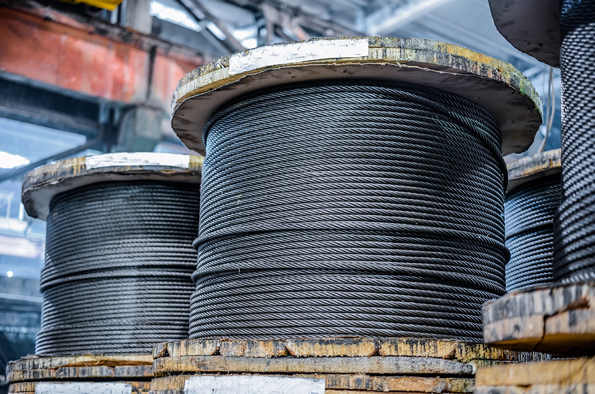
Wire rope is stored on reels or coils and has to be carefully handled when it is being removed. To ensure excellent performance, the wire rope should not be dropped during removal. If the reel or coil is dropped or damaged, it can make handling the wire rope difficult and cumbersome. As the wire rope is removed from the reel, check to see that the reel is rotating as the wire is removed.
Wire rope is depended on for heavy lifting and is trusted to keep a load and people safe. As with all heavy duty equipment, wire rope must have a regular inspection schedule and be visually assessed during use.
Broken Strands – An easy way to check for broken strands is to run a cloth over the length of the wire. Broken strands that are found in critical areas, such as parts that pass through pulleys or sections that are regularly flexed, rubbed, or constantly worked must be replaced and repaired.
Internal wear – This can be tested by flexing the wire rope, which indicates if the interior has deteriorated, experienced fatigue, or become distorted.
For wire rope to perform at the highest level, it has to be stored in a well ventilated environment that is dry, covered, and not in contact with the floor. The avoidance of high moisture or damp conditions is an absolute necessity. While the wire rope is in storage, it should be moved regularly to keep the lubricant from wearing off.
Though lubricant is applied during the manufacturing of wire rope, it wears off during use. Lubrication is the key to the performance of wire rope because it helps prevent abrasion as the wires rub against one another. Relubrication should be applied after the original lubricant has worn off.
Wire rope is a tool and must be cleaned regularly as with any for


 8613371530291