
wire rope drive mechanism manufacturer
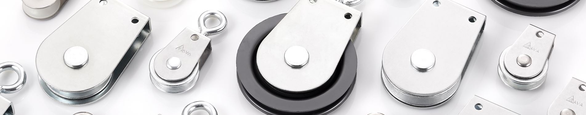
Our team understands that choosing the right cable assembly manufacturer, and pulleys for your cable assemblies requires thoughtful consideration, from bearing life, to minimum pulley diameter. Let Sava"s engineering expertise guide you toward the best selection of wire rope pulley wheels.
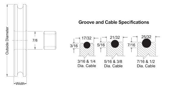
When cable is used over pulleys, the cable life can be significantly prolonged by proper pulley groove design. Laboratory tests on wire rope pulleys prove that improper groove design reduces cable bending life up to 90%. These same tests show that doubling a pulley diameter can increase cable bending life up to thirteen times what is otherwise typical. Also, pulley diameters less than sixteen rope diameters fall into a range in which cable life is relatively low.
Rope Drive - You find here 7 suppliers from Germany and ✓ China. Please obtain more information on spare parts, servicing, maintenance, Repair, repair or accessories directly from the registered companies.
Are you looking for Rope Drive. IndustryStock"s product and service search engine will not only help you find relevant results for Rope Drive but also related products and services. All contact information of listed Rope Drive manufacturers, traders, suppliers and dealers are freely available to all users.

Flexible cable realize high flexibility and torque force transmission, ideal for drive cable for atherectomy, impeller, anchoring, and device release mechanism.
Gold wire features 99.99% purity and offers researchers a noble metal with biological inertness. Gold is softer than platinum and this feature may be used as an advantage in some applications.
... kPSI the more brittle the wire is but the better it retains its shape. The high kPSI wire is good for making straight electrodes that need to penetrate through tissue. The low kPSI is a softer more flexible ...
our magnesium alloy wire adopts the technical of super plasticity forming to improve the shortcomings of the low plasticity, which has the excellent plasticity much more than the normal magnesium alloys under the room ...

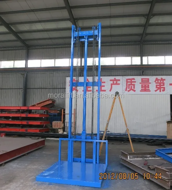
Full service distributor of new and used material handling low headroom, electric, chain and wire rope hoists. Variable capacity electric chain hoists can be mounted on overhead cranes including single, double or box girder types. Speed controls, radio control and hazardous environment options are available for chain hoists. Heavier capacity electric wire rope hoists can be used for industrial applications, and can be fitted with speed controls, radio remote control and other custom features. replacement or performance parts. Capabilities include turnkey installation and CAD designing. Crane maintenance, rebuilding, upgrades, inspection, retrofitting and safety training services are available. 24-hour emergency services are available. Meet ASME standards.
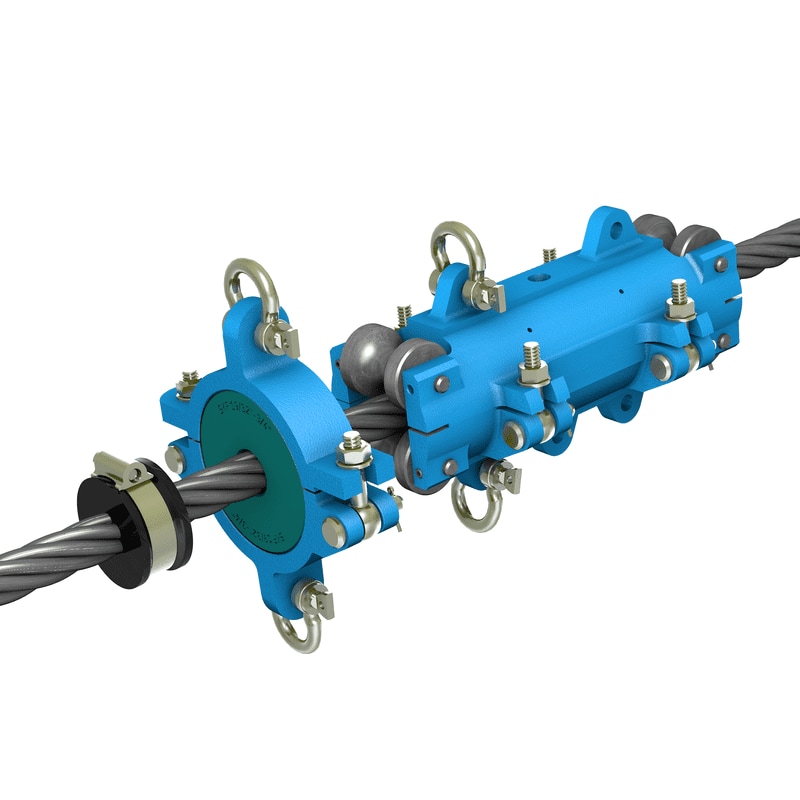
This invention relates generally to the field of mechanical systems for providing reciprocating, linear motion for a movable structure or work piece relative to a fixed structure or work piece. More particularly, the invention relates to a drive mechanism providing reciprocating, linear motion from rotational motion of a motor, using a novel cable or wire rope drive mechanism. The invention is susceptible to many possible uses and installations, examples being drive systems for use in automated instruments for processing biological samples, and stacking systems for stacking cards or card-like bodies in a tray, which happen to be of particular applications presently employed by the present inventors. However, other possible uses of the invention in different types of machines and systems will be apparent to persons skilled in the art from the following detailed description, and thus the invention relates, primarily, to reciprocating drive mechanisms for a moveable work piece. [0002]
Drive mechanisms for providing reciprocating, linear movement of a moveable work piece relative to a stationary work piece or structure are known. An example is described in the patent of Clifford W. Karl et al., U.S. Pat. No. 5,674,454, assigned to the assignee of the present invention. Generally, the "454 patent describes a stacking system for stacking flat, thin, card-like objects in a magazine. The stacking system has a moveable push plate that is used to stack the objects in the magazine. In FIG. 7 of this patent, a motor has a pinion gear with teeth which engage complementary teeth of a push rack that is coupled to the push plate. The rotation of the motor causes the push rack to move back and forth in a linear fashion, causing a push plate to move back and forth relative to the magazine and thereby providing a mechanism for stacking the objects in the magazine. [0004]
Other drive systems known in the art include Levine et al., U.S. Pat. No. 5,854,075, which describes a drive belt system for moving a carriage assembly relative to a magazine containing a plurality of slides. Other patents describing belt-type drive systems include Seto et al., U.S. Pat. No. 5,660,793; and Shindo et al., U.S. Pat. No. 5,470,533. Porte et al., U.S. Pat. No. 5,073,342, describes a simple reciprocating piston-acruated transfer mechanism. Forsstrom, U.S. Pat. No. 3,221,781 contemplates a similar type of arrangement for moving sample carriers about an analytical instrument. Other reciprocating belt and paddle-based drive mechanisms are described in the patent of William E. Seaton et al., U.S. Pat. No. 5,736,102, which is also assigned to the assignee of the present invention. [0005]
While the drive mechanism of the type described in the above-cited are work satisfactorily for many applications, the present invention is considered to be an improvement over these and other types of systems. The present drive mechanism and method is believed to provide improved reliability in extended use, and decrease the amount of maintenance for the user. Further, the design is quiet in operation. The design is easy to assemble and less costly to manufacture than systems based on the design of the above-cited Karl et al. patent. [0006] SUMMARY OF THE INVENTION
In a first aspect, a drive mechanism for providing reciprocating, liner motion for a movable work piece relative to a stationary work piece is provided. The drive system includes a motor rotating a drum in forward and reverse directions about a first fixed axis. The motor is fixedly mounted with respect to the stationary work piece, such as to a housing or other structure. The system further includes an elongate, substantially non-flexible cable having first and second ends, which are fixed with respect to the stationary work piece. The cable, which in a preferred embodiment takes the form of a wire rope, further comprises an intermediate portion extending between said first and second ends, with the intermediate portion being wound around the drum. [0007]
The drive mechanism of the invention can be installed in any type of system that may benefit from quiet, reliable operation of a reciprocating linear drive mechanism. Preferred embodiments would be in automated biological sample testing instruments, and in stacking systems for flat, thin card-like objects. However, the invention is not limited to such systems. [0010]
In another aspect of the invention, a method is provided for moving a moveable work piece relative to a stationary work piece using an elongate, substantially non-flexible wire rope or cable, the cable having a first end and a second end and an intermediate portion between the first and second ends. The method includes the step of attaching the first and second ends of said cable to a structure fixed with respect to the stationary work piece. The method includes the step of winding the intermediate portion of the cable about a drum coupled to a motor, with the motor fixed with respect to the stationary work piece. The intermediate portion of the cable is further wound around the first and second bearings, with the first and second bearings mounted to the moveable work piece such that the first bearing is positioned between the first end of the cable and the drum and the second bearing is positioned between the second end of the cable and the drum. The method includes the step of rotating the drum, whereby the step of rotating causes the first and second bearings to move relative to the drum and thereby move the moveable work piece relative to the stationary work piece.[0011]
When you need a wire rope hoist for use in extreme environments, your options can seem limited. Extreme environments require different specifications, especially when it comes to galvanizing operations, concrete, precast facilities, or other dusty, damp environments. Extreme environments require the right equipment. The Demag DMR Wire Rope Hoist with Co-Axial F10 motor is a new alternative to consider when you need precise positioning and productive lifting speeds.
Based on the Foot Mounted DMR configuration and including the trusted Demag FG Microspeed Drive, this model DMR is the definition of flexibility. The F DMR is flexible enough to meet the needs of crane modernizations and non-standard trolley gauges. When paired with the FG Microspeed Drive, it gives you very precise positioning, accommodates a high number of starts and stops, and moves large mass loads in short cycle times. The reason the DMR with the Co-Axial F10 motors can handle extreme conditions is due to the design principle of the combined FG microspeed and main motor drives. Both the main motor and microspeed motors are conical-rotor motors, meaning that braking is mechanical rather than being completed through a braking system. This makes the drives much less susceptible to vibration, high ambient temperatures and other influences found in extreme environments.
When you need a wire rope hoist for an extreme environment and gives you precise positioning, see what the Demag F DMR Wire Rope Hoist with Co-Axial F10 motor can do for your operations. Read more about it on our blog and contact us to learn more about Demag DMR configurations and the F DMR wire rope hoist with co-axial F10 motor!

Rope drive is a form ofbelt drive, which is used for mechanical power transmission. Rope drives use multiple circular section ropes instead of single flats or V-belts. The rope drives are widely used where a large amount of power is to be transmitted, from one pulley to another, over a considerable distance.
The fibre ropes operate successfully when the pulleys are approximately 60 meters apart, while wire ropes are used when the pulleys are separated by 150 meters.
Wire rope is several strands of metal wire twisted into a helix forming a composite rope, in a pattern known as laid rope. Larger diameter wire rope consists of multiple strands of such laid rope in a pattern known as cable laid.
In the lifting and rigging industries, wire rope is attached to a crane or hoist and fitted with swivels, shackles or hooks to attach to a load and move it in a controlled matter. It can also be used to lift and lower elevators, or as a means of support for suspension bridges or towers.
Wire rope is a preferred lifting device for many reasons. Its unique design consists of multiple steel wires that form individual strands laid in a helical pattern around a core. This structure provides strength, flexibility, and the ability to handle bending stresses.
In stricter senses, the term wire rope refers to a diameter larger than 3/8 inch (9.52 mm), with smaller gauges designated cable or cords. Initially wrought iron wires were used, but today steel is the main material used for wire ropes.
Wire ropes are made from cold-drawn wires to increase strength and durability. It may be noted that as its size decreases the strength of the wire rope increases. The various materials used for wire ropes in order of increasing strength are iron, cast steel, extra-strong cast steel, steel, and alloy steel.
Wire ropes were developed starting with mining hoist applications in the 1830s. Wire ropes are used dynamically for lifting and hoisting in cranes and elevators, and for transmission of mechanical power.
It is also used to transmit force in mechanisms, such as a Bowden cable or the control surfaces of an airplane connected to levers and pedals in the cockpit.
A wire rope clip, sometimes called a u-bolt clamp or u-bolt clip is used to clamp the loose end of a length of wire rope, once it has been looped back to form an eye. These fittings consist of a u-bolt and has a saddle secured by two nuts.
The advantages of a wire rope are that they are more resistant to wear, have better crushing resistance, and high strength compared to a round strand wire rope of equal diameter and classification. However, a swaged wire rope may have less bending fatigue resistance.
Wire ropes are made from various grades of the steel wire with tensile strength ranging from 1200 to 2400 MPa. The wires are first given special heat treatment and then cold drawn for high strength and durability of the rope. Steel wire ropes are manufactured by specialized machines.
First, strands such as 7, 19, or 37 of the wire are routed into a strand, and then a number of strands, usually 6 or 8, are rotated about the core or center to form the rope. The core may be made of hemp, jute, asbestos, or soft steel wire. The core must be continuously saturated with lubricant for the long life of the core as well as the entire rope.
Asbestos or soft wire cores are used when the ropes are subjected to radiant heat such as cranes working near furnaces. However, a wire core reduces the flexibility of the rope, and such ropes are used only where they are subjected to high compressions. Such as in the case of the wounding of multiple layers on a rope drum.
Cross or Regular Laying Ropes: In these types of ropes, the direction of twisting of wires in the strides is opposite to the direction of the twist of the stand. These types of ropes are the most popular.
Parallel or lang lay ropes: In these types of ropes, the direction of rotation of the strands in the strands is similar to the strands in the rope. These ropes have a better bearing surface but are easily split and twisted when loaded. These ropes are more flexible and the wearer is more effective. Since such ropes have a tendency to rotate, they are used in lifts and waved by guide methods and also as rope ropes.
The direction of the laying of ropes can be right-handed or left-handed, depending on whether the strands form a right-handed or left-handed helix. But right-handed ropes are most commonly used.
Fibre ropes are made from fibres of varying length depending on their source. these are twisted up into yarns, and the twist given binds the fibres firmly together so that they hold by friction when the yarn is subjected to strain. The yarns are then laid up to form rope.
Ropes for transmission power are usually made of fibrous materials such as cannabis, manila, and cotton. Since hemp and manila fibres are rough, the ropes made of these fibres are not very flexible and have poor mechanical properties. The hemp rope has less strength than the Manila ropes.
When the hemp and manila ropes are bent over the sheave. The fibres cause some sliding, causing the rope to rub internally. To reduce this defect, rope fibres are lubricated with a tar, elongated, or graphite. Lubrication also makes the rope moisture-proof. Hemp ropes are suitable only for hand-operated hoisting machinery and for tackling rope tack, hooks, etc.
The cotton cord is very soft and smooth. Lubrication of cotton ropes is not necessary. But if it is done, it reduces the external wear between the rope and its edge grooves. It may be noted that Manila ropes are more durable and stronger than cotton ropes. Cotton ropes are more expensive than Manila ropes.
Manila and cotton ropes typically have a diameter of 38 mm to 50 mm. The size of the rope is usually specified by its circumference or ‘circumference’.
The ultimate tensile braking load of fibre ropes varies greatly. For Manila ropes, the average value of ultimate tensile braking load can be taken as 500 D 2 kN and for cotton ropes, it can be taken as 350 D 2 kN, where D is the diameter of the rope in mm.
Power transmission over long distances is the main application of rope drive. Rope drives are used to drive systems that are more than 8 meters in distance using a distance power transmission system. Metal ropes are used for distances beyond sixty meters. It is commonly seen in elevators and cranes.
Rope drive is a form of belt drive, which is used for mechanical power transmission. Rope drives use multiple circular section ropes instead of single flats or V-belts. The rope drives are widely used where a large amount of power is to be transmitted, from one pulley to another, over a considerable distance.
Wire rope is several strands of metal wire twisted into a helix forming a composite rope, in a pattern known as laid rope. Larger diameter wire rope consists of multiple strands of such laid rope in a pattern known as cable laid.
A wire rope clip sometimes called a u-bolt clamp or u-bolt clip is used to clamp the loose end of a length of wire rope, once it has been looped back to form an eye. These fittings consist of a u-bolt and have a saddle secured by two nuts.
The term cable is often used interchangeably with wire rope. However, in general, wire rope refers to diameters larger than 3/8 inch. Sizes smaller than this are designated as cable or cords. Two or more wires concentrically laid around a center wire is called a strand.
Available in various constructions, sizes and finishes, wire rope is a versatile material that can be used to (among other things) lift, hoist, separate, position, secure, remove, repair, readjust, support and brace items in a safe and effective manner. Wire rope was initially designed to assist in the mining industry.
Dyneema is the world’s strongest fiber-producing ropes that are 15 times stronger than steel wire ropes of the same weight and has become one the most trusted fiber ropes over generic HMPE ropes and steel cable wire ropes for all rigging, maritime, mooring, and towing rope applications.
Overall, wire rope is stronger than chain. The multi-strands of continuous wires give wire rope its strength, whereas a chain is joined together with links. These joins are the weakest part of a chain and can break under heavy loads.
Wire rope is a preferred lifting device for many reasons. Its unique design consists of multiple steel wires that form individual strands laid in a helical pattern around a core. This structure provides strength, flexibility, and the ability to handle bending stresses.
The various materials used for wire ropes are iron, cast steel, extra strong cast steel, steel, and alloy steel, in order of increasing strength. For some purposes, wire rope can also be made from copper, bronze, aluminum alloys, and stainless steel.
In general, the higher wire count of a 7×19 typically makes it a better choice for winches, garage doors, and other applications that require tighter and more frequent turns, while the rigidity of a 7×7 makes it a good choice for automotive and aircraft controls.
Braided rope is stronger and is nicer on the hands than twisted rope, but it’s a pain to splice yourself. This means if you’re using a windlass and chain, and you are doing your own splicing, you’ll probably need to use twisted rope.
6 x 19S (Seale) -This is a good rope to withstand abrasion or crushing on the drum but its fatigue resistance is decreased. 6 x 25FW (Filler Wire) – To most wire rope users, 6 x 19 means 6 x 25 filler wire. It is a common rope in the 6 x 19 classification.
A wire rope is stronger because the material that makes it is continuous, i.e. without joins. In a chain, individual links must be closed by joining their ends, and that reduces the tension it can handle.
Compared to chain, steel wire ropes have a higher strength-to-weight ratio, making them easier to install and lighter on the floating structure. Steel wire ropes are most commonly constructed of many thin steel wires wound into strands, which are then wound around a central core into the final wire rope.
You should generally use equipment with a working load limit that is rated for weight at least five times higher – or 250,000 lbs. in this case. This recommendation is all thanks to the wire rope safety factor.
A rope that has more strands exhibits greater flexibility than one with fewer strands. Crush resistance: Although wire rope with a fiber core offers the most flexibility, it also demonstrates less resistance to crushing. If crushing is not a concern but flexibility is, fiber core wire rope is ideal.
The helix or spiral of the wires and strands in a rope is called the lay. Regular lay denotes rope in which the wires are twisted in one direction, and the strands in the opposite direction to form the rope. … These ropes are more likely to twist, kink and crush than regular lay ropes.

The first multiple rope drive was a 9-rope drive of 200 bhp produced by Combe Barbourmanila hemp.vee pulley, as part of a Van Doorne or Variomatic transmission.textile machinery and differential speed gearing was often needed as part of the spinning process, where one shaft could be smoothly adjusted to run slightly faster or slower than another.
Rope drives were most widely used for power-transmission in mills and factories, where a single mill engine would have a large rope drive to each floor, where lineshafts across each floor distribute power to the individual machines. These multiple rope drives replaced the earlier technique of a vertical wrought iron shaft with bevel gears at each floor. They remained in use for as long as mills were driven by central steam engines, rather than individual electric motors.Droylesden split the output of one motor between two floors with two new rope drives.gas engines running on producer gas. A Yorkshire mill converted to use a 1,000 hp Allen diesel engine in 1938, and retained the rope drives.
Shaft drives had often used gearing from the engines to increase their speed, and thus their power transmission. This was avoided for rope drives, as the rope"s maximum useful speed could be achieved from the engine"s flywheel and flexibility of the ropes led to backlash in the gearing.
US practice sometimes used a single rope, looped between floors and tensioned by an idler pulley, but this system was not used in the UK and each loop was tensioned between its two pulleys by one of them being movable. Rope drives were also cheaper than belts - around a quarter of the price.
The rope drives were placed in a large diagonal shaft at the side of the building, usually windowless and distinctively visible from outside the building.
Rope drives required a larger such shaft than comparable belt or shaft drives. As the open shaft represented a channel for transmitting fires, unlike the narrow holes of a shaft drive, it needed careful fireproofing from the loom floors.
It was sometimes arranged for large drives that the engine drove a set of horizontal ropes to a pulley on a layshaft or "second motion shaft" alongside the engine house, then diagonally up through the shaft.
Vertical shafts were not widely used for rope drives in the UK, although were used for belts, as diagonal ropes could be made self-tensioning on the lower pulley under their own weight.
Back to the original analysis I made. The ratio of usable force difference to sum of tether tension forces is approx (0.45/2.45)~0.18 which is approx 1/5. So if the rope speed with slack return tether is approx 1/3 windspeed, with a 180 degree pulley at either side the rope speed must be minimum 5/3 times windspeed to transfer all the produced power.
Actually, one could probably chalk this up as +1 for rope drive vs yoyo as there will be less creeping on the drum (for yoyo the tether is reeled in at low tension and reeled out in high tension, leading to slippage and friction and thus wear on the tether). On the other hand, the tether on a rope drive will be passing the pulley 15 times more frequently compared to yoyo. I am unsure which of these is better

Transmission pulleys are typically found in automatic transmissions of cars and trucks. Pulleys change the speed at which fluid circulates through the transmission, effectively changing the gear ratio. There are two types of wire rope drive pulley: solid or fluid-filled. Solid transmission pulleys take the brunt of the power from the engine and send it to the other parts of the power train. Fluid-filled transmission pulleys don"t do anything on their own but when the solid transmission pulley sends drive power around it, friction in fluid-filled transmission pulleys dissipates a third of that power making it a very useful feature.
We bring you all sorts of pulley systems, including small pulleys, winch pulleys, and heavy-duty pulleys. A fixed pulley is attached to the vehicle"s driveshaft and has a fixed connection to the transmission. Compound pulleys, on the other hand, do not attach directly to the driveshaft or transmission. It has its drive system separate from the motor. Lifting pulleys and movable pulleys can be regulated by changing their position concerning both the transmission and driveshaft.
V-belt pulleys are used as a support pulley with rubber belts across two or more shafts. The V-belt pulley is a specially designed pulley used with V-belts. The teeth on these pulleys are angled at 14.5 degrees allowing the belt to follow the curve of the pulley smoothly. S-belt pulleys consist of a single sheave wheel, which is the wheel without the grooves. Without these types of pulleys, proper transmission operation would be impossible. Find more wholesale wire rope drive pulley at preferential bulk rates.


 8613371530291