
wire rope electric winch free sample

The pulling capacities of electric winch with free spool is amazing, ranging from 80 kg to 10,000 kg. The winding range of the winch cable depends varies from 8 meters to over 300 meters depending on the model of electric winch with free spool. Hand winches are suitable for lifting or hauling operations.
The power winches have multi-layered cable winding. They have great load and winding capacities, which makes them a popular choice for hauling activities, and they are essentially intended for trailers. Some manual winches are equipped with a drum clutch so that the cable can be unwound by pulling the cable, this is much easier than using the crank.
The hydraulic winches are designed to adapt with various integrators up to 1,500 kg. They have permanent automatic brakes with up to two speeds available, and an integral protective cover. We offer you a wide choice of wholesale electric winch with free spool models.
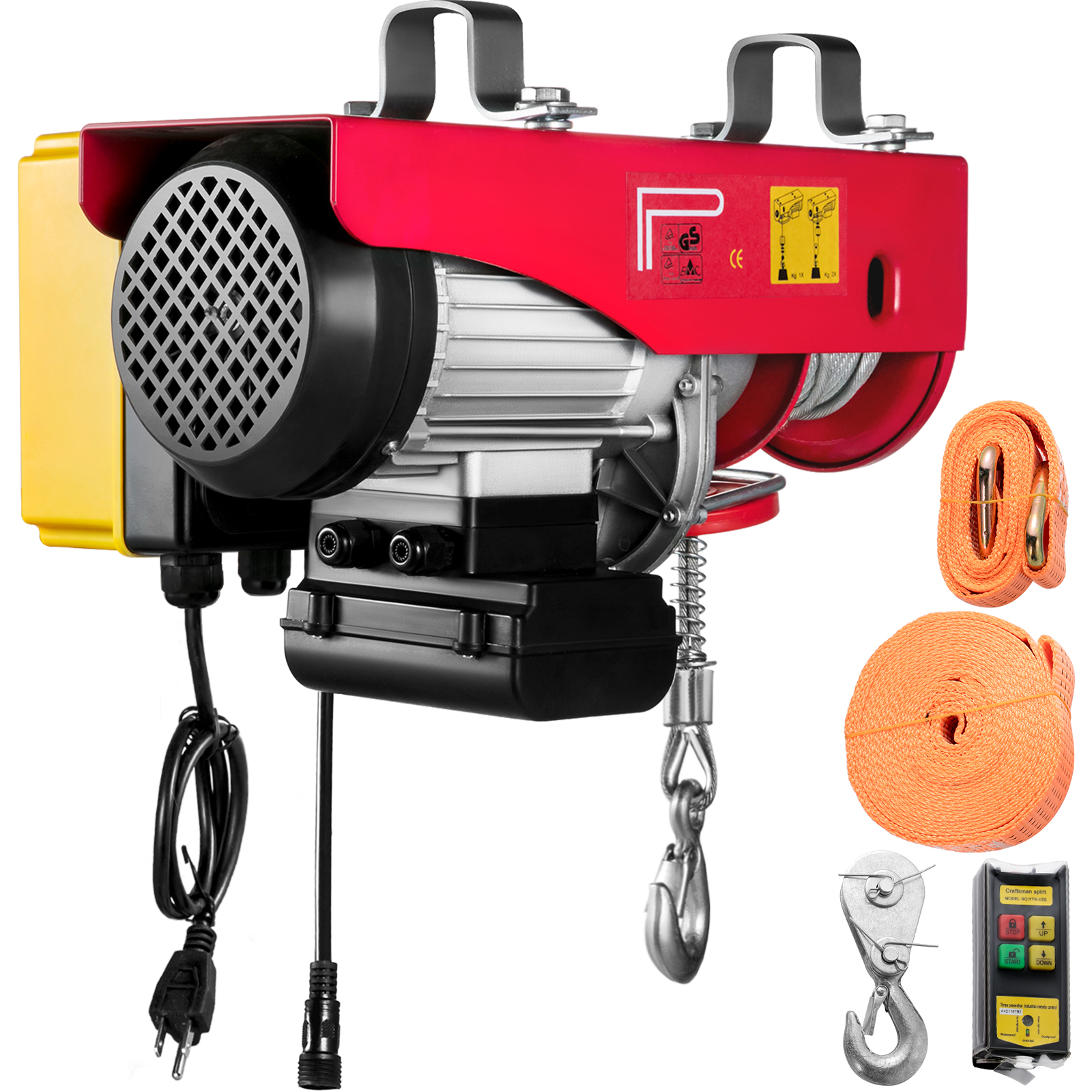
You can also opt for portable winches which are equipped with steel wire cable. They also have a power cord with a splash-proof plug and a circuit breaker. The waterproof plug provides you with greater safety and remote control. Enjoy the advanced electric technology of our winching solutions at preferential prices. Your satisfaction is our priority, that’s why we bring you leading winches from international wholesalers.

The winch can be mounted on any flat surface in any position. The design of the winches complies with DIN 15020 - power unit group 1 Bm/M3, DGUV regulation 55 (winches, lifting and pulling equipment) and the EC Machinery Directive.

Wire rope winches series DS-EWA are designed explicitly for performance, efficiency and safety and offer many advantages and options. Their extremely compact,
practical cube design and universal rope lead-offs allow individual applications in almost any position and make them powerful aids of lifting and pulling loads.
Wire rope is shipped in cut lengths, either in coils or on reels. Great care should be taken when the rope is removed from the shipping package since it can be permanently damaged by improper unreeling or uncoiling. Looping the rope over the head of the reel or pulling the rope off a coil while it is lying on the ground, will create loops in the line. Pulling on a loop will, at the very least, produce an imbalance in the rope and may result in open or closed kinks (Fig. 18). Once a rope is kinked, the damage is not repairable. The kink must be cut out or the rope is unfit for service.
Figure 18.Improper handling can create open (a) or, closed kinks b). The open kink will open the rope lay: the closed kink will close it. Starting loop (c): Do not allow the rope to form a loop. If. however, a loop does form and is removed at the stage show. a kink can be avoided. Kink (d): In this case. the looped rope was put under tension, the kink was formed. the rope is permanently damaged.
There are three methods to perform this step correctly:The reel is mounted on a shaft supported by two jacks or a roller payoff (Fig.19). Since the reel is free to rotate, the rope is pulled from the reel by a workman holding the rope end, and walking away from the reel as it unwinds. A braking device should be employed so that the rope is kept taut and the reel is restrained from over-running the rope. This is necessary particularly with powered de-reeling equipment.
Another method involves mounting the reel on an unreeling stand (Fig. 20). It is then unwound in the same manner as described above (1). In this case, however, greater care must be exercised to keep the rope under tension sufficient to prevent the accumulation of slack. Slack can allow the rope to drop below the lower reel head and be damaged or loose wraps on the reel to fall
In another accepted method, the end of the rope is held while the reel itself is rolled along the ground. With this procedure, the rope will payoff properly however, the end being held will travel in the direction the reel is being rolled. As the difference between the diameter of the reel head and the diameter of the wound rope increases, the speed of travel will increase.
Figure 19. The wire rope reel is mounted on a shaft supported by jacks. This permits the reel to rotate freely. and the rope can be unwound either manually or by a powered mechanism.
When re-reeling wire rope from a horizontally supported reel to a drum it is preferable for the rope to travel from the top of the reel to the top of the drum; or, from the bottom of the reel to the bottom of the drum (Fig. 21). Re-reeling in this manner will avoid putting a reverse bend into the rope during installation. If a rope is installed so that a reverse bend is induced, it may cause the rope to become "twisty" and, consequently, harder to handle. When unwinding wire rope from a coil, there are two suggested methods for carrying out this procedure in a proper manner:
1) One method involves placing the coil on a vertical unreeling stand. The stand consists of a base with a fixed vertical shaft. On this shaft there is a "swift," consisting of a plate with inclined pins positioned so that the coil may be placed over them. The whole swift and coil then rotate as the rope is pulled off. This method is particularly effective when the rope is to be wound on a drum.
2) The most common as well as the easiest uncoiling method is merely to hold one end of the rope while rolling the coil along the ground like a hoop (Fig. 22). Figures 23 and 24 show unreeling and uncoiling methods that are most likely to cause kinks. Such improper procedures must be avoided in order to prevent the occurrence of loops. These loops, when pulled taut, will inevitably result in kinks. No matter how a kink develops, it will damage strands and wires, and the kinked section must be cut out. Proper and careful handling will keep the wire rope free from kinks.
Drums are the means y which power is transmitted to the rope and then to the object to be moved. For the wire rope to pick up this power efficiently and to transmit it properly to the working end, the installation must be carefully controlled. If the drum is grooved, the winding conditions should be closely supervised to assure adherence to the following recommended procedures:
I) The end of the rope must be secured to the drum by such means as will give the end termination at least as much strength as is specified by the equipment manufacturer.
2) Adequate tension must be maintained on the rope while it is being wound so that the winding proceeds under continuous tension. Back tension applied to the rope during installation" should be from 2 to 5% of the minimum breaking force of the rope being installed.
4) It is preferable to have at least three dead wraps remaining on the drum when the rope is unwound during normal operation. Two dead wraps are a mandatory requirement in many codes and standards. If the wire rope is carelessly wound and, as a result, jumps the grooves, it will be crushed and cut where it crosses from one groove to the other. Another, almost unavoidable problem is created at the drum flange; as the rope climbs to a second layer there is further crushing and the wires receive excessive abrasion.
drum grooves relative to the actual rope diameter. Wire rope is normally manufactured to a plus tolerance. (See Table 3.) The oversize tolerance of the rope must be taken into account or the rope will be damaged by poor spooling caused
inches. Yet, by Federal standards, a 1/4-inch rope may have a diameter as large as .265 inches. If a rope of this size were to be operated on a drum with a .250 inch pitch, crowding would occur and the rope would be forced out of the groove.
Installation of a wire rope on a plain (smooth) face drum requires a great deal of care. The starting position should be at the correct drum flange so that each wrap of the rope will wind tightly against the preceding wrap (Fig. 32). Here too, close supervision should be maintained during installation. This will help make certain that:
2 ) Appropriate tension on the rope is maintained as it is wound on the drum. Back tension applied to the rope during installation should be from 2 to 5% of the minimum breaking force of the rope being installed.
4) It is preferable to have at least three dead wraps remaining on the drum when the rope is unwound during normal operation. Two dead wraps are a mandatory requirement in many codes and standards. Loose and uneven winding on a plain (smooth) faced drum can and usually does create excessive wear, crushing and distortion of the rope. The results of such abuse are shorter service life and a reduction in the rope"s effective strength. Also, for an operation that is sensitive in terms of moving and spotting a load, the operator will encounter control difficulties as the rope will pile up, pull into the pile and fall from the pile to the drum surface. The ensuing shock can break or otherwise damage the rope.
Figure 32. By holding the right or left hand with index finger extended, palm up or palm down, the proper procedure for applying left-and right-lay rope on a smooth drum can be easily determined.
The proper direction of winding the first layer on a smooth drum can be determined by standing behind the drum and looking along the path the rope travels, and then following one of the procedures illustrated in Figure 32. The diagrams show: the correct relationship that should be maintained between the direction of lay of the rope (right or left), the direction of rotation of the drum (overwind or underwind) and winding from left to right or right to left. Order Wire Rope & Cable
Many installations are designed with requirements for winding more than one layer of wire rope on a drum. Winding multiple layers presents some further problems.The first layer should wind in a smooth, tight helix which, if the drum is grooved,
is already established. The grooves allow the operator to work off the face of the drum, and permit the minimum number of dead wraps. A smooth drum present" an additional problem, initially, as the wire rope must be wound in such a manner that the first layer will be smooth and uniform and will provide a firm foundation for the layers of rope that will be wound over it. The first layer of rope on the smooth drum should be wound with tension (2 to 5% of the minimum breaking force of the rope) sufficient to assure a close helix - each wrap being wound as close as possible to the preceding wrap. The first layer then acts as a groove which will guide the successive layers. Unlike wire ropes operating on grooved drums, the first layer should not be unwound from a smooth-faced drum with multiple layers. After the rope has wound completely across the face of the drum (either smooth or grooved), it is forced up to a second layer at the flange. The rope then winds back across the drum in the opposite direction, lying in the valleys between the wraps of the rope on the first layer. Advancing across the drum on the second layer, the rope, following the "grooves" formed by the rope on the first layer, actually winds back one wrap in each revolution of the drum. The rope must then cross one or two rope "grooves" (depending upon the type of grooving - single or double cross-over) in order to advance across the drum for each turn. The point at which this occurs is known as the cross-over. Cross-over is unavoidable on the second, and all succeeding layers. Figure 33 illustrates the winding of a rope on the second layer from left to right, and from right to left-the direction is shown by the arrows.
At these cross-over points, the rope is subjected to severe abrasion and crushing as it is pushed over the "grooves" and rides across the crown of the first rope layer. The scrubbing of the rope, as this is happening, can easily be heard.
Helical grooving does not employ a built in cross-over and does not work as well for multiple layers spooling as a counterbalanced drum because it does not have the cross-over and does not consistently put the rope in the proper position at the
Counterbalance grooving with two cross-overs is made so that each wrap of rope winds parallel to the drum flange for a distance less than half the circumference around the drum, then follows a short cross-over to complete half the drum circumference. The cross-over is at an angle with the drum flange and displaces the rope laterally by half the pitch of grooving.
The grooving for this type of winding is similar to the parallel grooving except that half the drum circumference is laterally displaced from the other half by half the pitch of grooving, and between these two halves the grooves make short cross-overs to guide the rope properly. The two cross-over areas are on opposite sides of the drum, or 1800 apart.
Since the lateral displacement of each cross-over is one half the pitch of grooving, or one half the displacement of the cross-overs encountered with other types of winding, "throw" of the rope is reduced, decreasing the whipping action. However, if the interval between these displacements happens to match the rope"s vibration cycle, whipping can still become severe because this action is cumulative.
With counterbalance winding, the change of layers can be controlled better than with other systems and is preferred when a rope must wind in many layers on the drum.
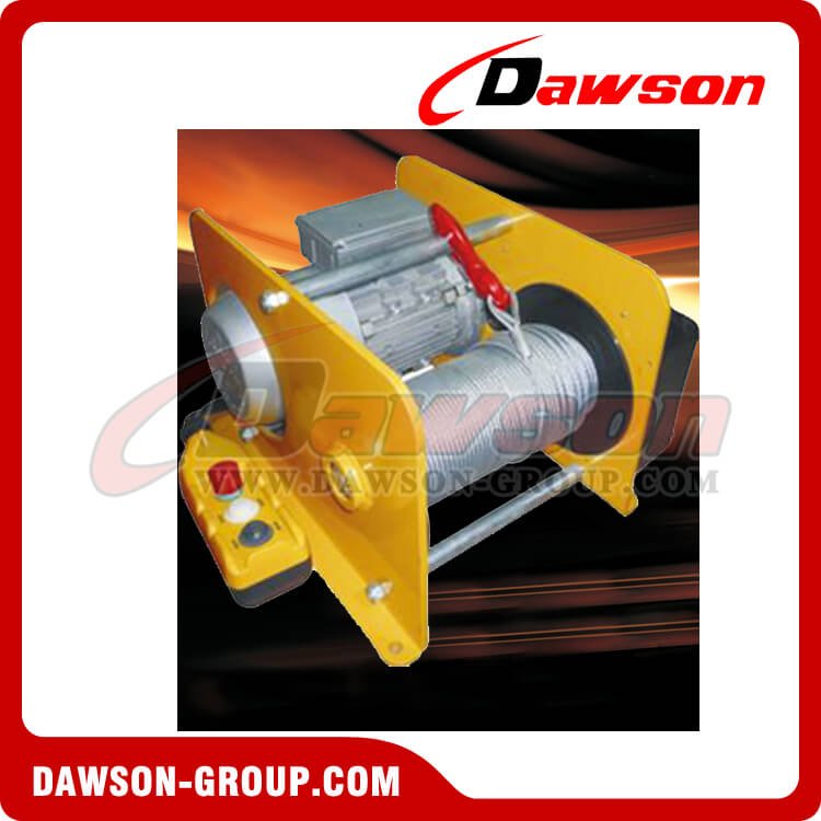
We have manufactured this Electric Wire Rope Hoisting Winch since 2006. Electric Wire Rope Hoisting Winch consists of hydraulic motor, planetary reducer, disc brake, oil distributor and steel structure. Our Electric Wire Rope Hoisting Winch has its own valve group which makes hydraulic system more simple and increases stability of the transmission device.
This Electric Wire Rope Hoisting Winch can lift and put down stably without empty hook vibrating and twice falling during hoisting. Our Electric Wire Rope Hoisting Winch has advantages in high efficiency, low energy consumption, low noise and compact structure due to our accurate design proposal. This Electric Wire Rope Hoisting Winch is widely applied in railway and automobile crane, ship, oil field, coal mine, port and other lifting equipment. Our design group can customize Electric Wire Rope Hoisting Winch according to actual working condition.
Our company not only provides Electric Wire Rope Hoisting Winch, but also provides whole hydraulic system and power source. The hydraulic motor, planetary gearbox and system of Electric Wire Rope Hoisting Winch are designed and manufactured by our own factory. So the quality and delivery time can be controlled and guaranteed. We can also supply timely after-sale service and technique support.

This hoist meets the highest requirements, namely EN 14492-2, with a safety factor of more than 5 for the steel wire rope or more than 7 for the high quality synthetic rope. This is a special synthetic rope which is even stronger than the steel wire rope of the same thickness.
This hoist has a special non-twisting steel wire rope. This ensures that the load remains neatly under the winch and does not rotate by itself during lifting. The same applies to the winch rope.
Your load will hang securely even if the power fails. The up and down movement is completely controlled by the winch. It is ideal for lifting ship anchor pipes, loading material with a davit into a car or loading and unloading a load on board or from a ship. Wherever direct current is available, this compact electric hoist can be used.
The relay box is specially separated from the winch with long power cables. You can then mount the winch at a desired location and the hoist takes up little space. This winch hoist is optimally compact so that it can be placed in small rooms.

Winches and hoists are mechanical devices used for pulling and for raising and lowering loads. They can be powered by hand or by air, hydraulic, or electric motors. Both winches and hoists rely on wire rope, cable, or chain for connecting to their loads. Winches will sometimes use fiber rope also, as in many marine applications. Capacities of both are usually rated in tons.
Primarily, hoists operate on suspended loads, while winches drag loads horizontally or on inclines of up to 30° with the weight at least partly supported by some means other than the winch itself. Winches are sometimes known as “come-alongs” and “cable pullers” but the function is similar. Hoists, because they can and routinely do lift loads overhead, require brakes to hold the loads and check lowering rates. Hoists generally require a higher factor of safety due to the probability that loads will be overhead; winches are used to lift loads also, but they do so through top-mounted sheaves. Winches are not mounted overhead as hoists are. Both hoists and winches require care in their use as the failure of either can unleash great potential energy that can injure bystanders.
Hand-operated winchesand hoists can be light enough to be portable. Powering winches and hoists can be via electric motors; or, for better speed control and operability in explosive environments, air motors; or, where hydraulic power is available, compact hydraulic motors. Hand-operated devices usually take the form of levers, cranks, or handwheels.
Hoists are often suspended on overhead trolleys which in turn ride on I-beam tracks. Winches can be mounted on decks, trucks, walls, etc. Winches are used on ships, in railyards, and in a host of vehicular applications from tow trucks to refuse haulers.
The ability to pull or lift loads comes from mechanical advantage imparted by worm or gear drives and the moment arm achieved by winding rope over a drum. A chain is generally used up to a certain capacity, after which rope is commonly employed. When buying a chain-based hoist it is important to determine in advance how long the chain must be as it cannot be easily lengthened by adding links.
Winches can range from very small boat trailer varieties to very large barge and towboat winches used for mooring and towing. Boat trailer types usually consist of a rotary crank coupled to a drum via spur gears, employing ratcheting pawls. Ratcheting can be released to allow the winch to freewheel when pushing the boat into the water. The same basic architecture can be scaled-up to produce hand-powered winches of greater capacity. Sometimes a worm gear replaces a spur gear to eliminate the pawls. In larger sizes, handwheels often replace cranks. Brakes can be incorporated into the smallest of winches to eliminate the dangers from freewheeling.
Winches can be motorized via electrical, pneumatic, or hydraulicpower. The same transmissions found on hand winches may be used to power the drum on motorized winches, with several other transmission styles available as well. These include planetary and bevel gearing. Sometimes transmission elements are combined, such as a spur gear driving a worm, in order to step down the rpm of the motor.
The primary difference between hoisting and hauling is what the load would do theoretically if the rope was cut. A load being hauled would stay put, while one being hoisted would fall. Determining line load is more difficult for hauling than it is for hoisting because hoisting only needs to consider the weight of the load being lifted. Hauling must take into account friction as well as the slope up which the load is being hauled. Wheeled loads moving along straight rails might only have a line load of 1-2% of the load weight (and carriage). But inclines and curves add to the line load, as would skidding a load over rough ground. Load cells can be used to determine actual line loads.
Winches use wire rope almost exclusively, unlike hoists, where chain is used frequently. About the only exceptions might be shipboard anchor windlasses, which drive anchor-chain links over pocket wheels much as chain hoists operate, capstan winches, which are often used with fiber rope, and small hand winches that use strap. Winch drums thus play a role in specifying equipment. Successive layers of rope will increase take-up speed while decreasing torque; the maximum torque will be applied during the drum’s first wrap. Ideally, the number of layers is minimized, but this can lead to wide drums, which present another problem. The wider the drum, the higher the fleet angle—defined as the angle between the center of the drum and the outermost wrap where the rope meets the first sheave. If this angle is high it may unduly stress the rope. Idlers can be added which are driven either by the rope or by a separate mechanism to guide the rope onto the drum.
Drum diameter is likewise important. A drum diameter of at least 20 times the rope diameter is recommended for reasonable rope life, and 45 to 60 times rope diameter for a long rope life. Drums are usually smooth for light-duty applications but grooved for medium- and heavy-duty operation. Rope can pay-out from over the top of the drum or from the bottom. When using grooved drums, the lay of the grooves should be opposite the lay of the rope. In most instances right-hand lay rope will be used, necessitating that any grooving will be left-hand. Even on ungrooved drums, the attachment point for the rope is important as the rope needs to tighten against itself as it is wound in to prevent gaps between successive wraps.
Winches that do not incorporate self-locking worm drives may be fitted with transmission brakes. Exterior band brakes that act directly on the winch drums can also be specified. These may be manually actuated or pneumatically or hydraulically operated and can supply greater holding power than a transmission brake. Such brakes are often used in marine applications.
As with winches, hoists start very simply as hand-operated devices for handling light loads and progress up to heavy-duty, high-capacity machines. A hoist will often include a brake that both holds the load in position and makes lowering the load safer. The simplest brake, the so-called Weston self-energizing type, uses the weight of the load to force a friction plate or coned surface against the rotating element, requiring that the hoist be reversed to overcome the holding power of the brake. Some designs achieve the same effect by driving through a worm gear that cannot be back-driven, but these tend to be inefficient.
The same general idea can be easily mechanized by adding an electric, pneumatic, or hydraulic motor. Of these, electric motors probably offer the most economical solution, unless a source of compressed air is available. Then, pneumatic motors can offer several advantages:
the air motor can be controlled by a simple rope arrangement that runs from the ground to the forward and reverse valves on the motor situated above, eliminating the expense of a control pendant.
Electric motors for hoist operation are classified as lifting motors and are given a lifting motor rating based upon continuous run time, duty cycle, and starts per hour. Continuous run time defines the length of time a hoist can repeatedly lift, dwell, and lower its full rated load without overheating, and is sometimes called the “short-time rating.” Duty cycle and starts per hour are related, and ascertain how many lift-dwell-lower cycles can be made over a fixed interval without overheating the motor. Governing bodies such as ASME and ISO classify hoist motors by these ratings, the classes defining typical scenarios that the hoist motor might see. Thus, an ASME H3 class motor, for example, would be fit for duty in a general machine/fabricating shop, or in a warehousing environment, where the loads and use characteristics would be generally random. A class H4 motor, on the other hand, would expect to see more severe loading and use.
Most of what applies to chain hoists applies to wire-rope hoists as well. Chain hoists generally max out at around 5 tons, although standard chain hoists are available for capacities up to 25 tons. Chain hoists operate without a drum, wear better than wire rope, and withstand more abuse, but they are noisier and slower than rope hoists and have limitations on lift height. Above 10 tons, the choice is pretty much wire rope. Chain hoists do have an advantage over rope hoists when it comes to mounting. Because the chain winds through the hoist at a single point the hoist itself can be suspended from a single point. Rope hoists use a spool for taking in and paying out the rope and because the center of effort changes, these hoists require more elaborate mountings. This can be countered with twin-reeving arrangements.
As for mounting the hoist itself, users have several options. Hoists may be suspended on a single hook or eyebolt, or from a trolley that is manually propelled (pushed), geared (operated with a hand chain), or motor-driven. For low headroom applications, the hoist is often an integral part of the trolley.
A pneumatic chain hoist offers about the simplest controls possible: ropes extending up to valves on the motor operate forward and reverse motions while a mechanical brake takes care of the holding. From here, the next option is to drop a pendant, which is the first option for electrical hoists. Remote controls are also available.
Most electrical hoists use an upper limit switch or proximity sensor to stop motion at the top of travel and in many installations, one is included for the lower end of travel as well. Load limiters are installed to monitor the motor current to disable the lifting of loads beyond a system’s rated capacity. Dual speed operation is available with multi-contactor arrangements or can be accomplished with adjustable speed drives, which have the advantage of being able to tailor the acceleration ramp between speeds to minimize sway. Such systems are especially useful for motorized trollies. Inching and float control systems are available from some manufacturers, where float allows the hoist to respond to up or down pressure on the load itself, letting the hoist operator guide a workpiece into position with both hands.
Winch controls are often situated at the winch itself, or they can be on tethered pendants or remotely controlled. Winches used in mooring and similar marine operations are often hydraulically powered in order to provide constant line tension.
Lift capacity is the weight that can be supported by the hoist, usually given in tons. Similar to line load for winches, it takes into account not only the strength of the chain or rope but also the capacity of the motor, etc. It is determined by including a large factor of safety. Select a capacity greater than your heaviest load.
Line material is the media through which a force will be applied to lift or pull a load. The most common line materials used are chain and wire rope or cable. For smaller/lighter loads, fiber rope or strap or webbing may be used. Corrosion-resistant chains are available for corrosive environments.
The power source provides the motion to raise/lower or pull the load. The most basic hoists and winches are operated by manual chains or levers. Electrically powered hoists/winches are common for handling heavy loads. Air and hydraulic motors are used in explosive environments.
In addition to organizations that sponsor standards for hoists and winches such as OSHA and ASME, the following organizations can provide useful information on various aspects of their selection and use.
This article provided a basic understanding of winches and hoists and their selection, use, and maintenance in various environments. For more information on related products consult our other guides or visit the Thomas Supplier Discovery Platform to locate potential sources or view details on specific products.


 8613371530291