
wire rope eye splice strength manufacturer
A wire rope is a type of cable that includes several wire strands laced together to form a single wire. Generally, both the terms “wire” and “rope” are used interchangeably with “wire rope”; however, according to the technical definition, to be labeled a wire rope, the cable must have a thickness of at least 9.52 mm. As a versatile, high load capacity alternative to natural fiber ropes such as hemp and manila, wire rope provides motion transmission through nearly all angles, tie down, counterbalance, guidance, control, or lift.
Modern wire rope was invented by Wilhelm Albert, a German mining engineer, between 1831 and 1834. He developed them in order for work in the mines in the Harz Mountains. This rope replaced weaker natural fiber ropes, like hemp rope and manila rope, and weaker metal ropes, like chain rope.
Albert’s rope was constructed of four three-stranded wires. In 1840, a Scot named Robert Stirling Newall improved upon this model. A year later in the United States, American manufacturer John A. Roebling started producing wire rope, aimed at his vision of suspension bridges. From there, other interested Americans, such as Erskine Hazard and Josiah White, used wire rope in railroad and coal mining applications. They also applied their wire rope techniques to provide lift ropes for something called the Ashley Planes project, which allowed for better transportation and increased tourism in the area.
Approximately twenty-five years later, back in Germany in 1874, the engineering firm Adolf Bleichert & Co. was founded. They used wire rope to build bicable aerial tramways for mining the Ruhr Valley. Years later they built tramways for both the Wehrmacht and the German Imperial Army. Their wire rope systems spread all across Europe, and then migrated to the USA, concentrating at Trenton Iron Works in New Jersey.
Over the years, engineers and manufacturers have created materials of all kinds to make wire rope stronger. Such materials include stainless steel, plow steel, bright wire, galvanized steel, wire rope steel, electric wire, and more. Today, wire rope is a staple in most heavy industrial processes. Wherever heavy duty lifting is required, wire rope is there to facilitate.
Wire rope is strong, durable, and versatile. Even the heaviest industrial loads may be lifted with a well-made wire rope because the weight is distributed evenly among constituent strands.
There are three basic elements of which wire ropes are composed: wire filaments, strands, and cores. Manufacturers make wire rope by taking the filaments, twisting or braiding them together into strands, and then helically winding them around a core. Because of this multiple strand configuration, wire rope is also often referred to as stranded wire.
The first component, the filaments, are cold drawn rods of metal materials of varying, but relatively small diameter. The second component, the strands, can individually consist of as few as two or as many as several dozen filaments. The last component, the core, is the central element around which strands are wrapped; wire rope cores maintain a considerable amount of flexibility, while increasing strength by at least 7.5% over the strength of fiber core wire ropes.
The helical winding of the strands around the core is known as the lay. Ropes may be right hand lay, twisting strands clockwise, or they may be left hand lay, twisting strands counter-clockwise. In an ordinary lay, the individual strands are twisted in the opposite direction of the lay of the entire rope of strands to increase tension and to prevent the rope from coming unwound. Though this is most common Lang"s lay has both the strands and the rope twisted in the same direction while alternate lays, as the name suggests alternate between ordinary and Lang style lays. While alternative rope designs are available, the helical core design is often favored, as it allows a wire cable to hold a lot of weight while remaining ductile.
There are many design aspects that wire rope manufacturers consider when they are creating custom wire rope assemblies. These include: strand gauge (varies based on application strength, flexibility, and wear resistance requirements), wire rope fittings (for connecting other cables), lay, splices, and special coatings. Specially treated steel cable and plastic coated cables, for instance, are common to many application specific variations of wire rope such as push pull cable assemblies used in transferring motion between two points.
Suppliers typically identify wire cable by listing both the number of strands and the amount of wires per strand respectively, though stranded cable may alternatively be measured by their lay and length or pitch. For example, a door-retaining lanyard wire rope is identified by its 7 x 7 construction, and wire rope used for guying purposes is identified by its 1 x 19 construction. The most common types are 6 x 19, 6 x 25, 19 x 7, 7 x 7, 7 x 19, 6 x 26, and 6 x 36.
An ungalvanized steel wire rope variety. This uncoated wire rope can also be designed to resist spinning or rotating while holding a load; this is known as rotation resistant bright wire rope.
Also called a coiled wire rope, a coiled cable is a rope made from bundles of small metal wires, which are then twisted into a coil. Wire rope and cable can come in a huge variety of forms, but coiled cables specifically provide the benefits of easy storage and tidiness. Unlike other wire ropes, coiled cables do not require a spool for storage. Because it has been coiled, the cable will automatically retract into its spring-like shape when it is not in use, making it incredibly easy to handle.
A type of high strength rope, made of several individual filaments. These filaments are twisted into strands and helically wrapped around a core. One of the most common types of wire rope cable is steel cable.
Wire rope made not as one solid piece, but as a piece made up of a series of metal links. Wire rope chain is flexible and strong, but it is more prone to mechanical failure than wire rope.
Push pull cables and controls are a particular type of control cable designed for the positive and precise transmission of mechanical motion within a given system. Unlike their counterpart pull-pull cables, these wire rope assemblies offer multidirectional control. Additionally, their flexibility allows for easy routing, making them popular in a number of industrial and commercial applications.
Iron and steel are the two most common materials used in producing wire ropes. A steel wire is normally made from non-alloy carbon steel that offers a very high strength and can support extreme stretchable forces. For even more strength and durability, manufacturers can make stainless steel wire rope or galvanized steel wire rope. The latter two are good for applications like rigging and hoisting.
Technically, spiral ropes are curved or round strands with an assemblage of wires. This gathering of wires has at least one cord situated in the opposite direction of the wire in the outer layer of the rope. The most important trait of this rope is that all the wires included are round. The biggest benefit of this category of rope is that it does not allow the entrance of pollutants, water, or moisture.
Contain an assemblage of strands placed spirally around a core. Stranded rope steel wire patterns have different layers that cross each other to form an even stronger cable or rope. Stranded ropes contain one of three types of core: a fiber core, a wire strand core, or a wire rope core.
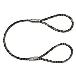
Provide an added level of security to a manufacturing production application. Wire rope slings are made from improved plow steel wire ropes that, apart from offering added security, also provide superior return loop slings. Plow steel wire ropes improve the life of a mechanism by shielding the rope at its connection points. The key objective of wire rope slings is to enhance the safety of an application while increasing its capacity and performance. Rope slings are also available in various sling termination options, such as hook type, chokers, and thimbles.
The eye in this rope sling is made using the Flemish Splice method. Just like a typical sling, a Permaloc rope sling improves safety and provides reverse strength meaning that the uprightness of the eye does not depend on the sleeves of the metal or alloy. Additionally, permaloc rope slings offer an abrasion resistance feature that makes them long lasting.
These slings have all the features that most other slings offer. However, compared to their counterparts, Permaloc bridle slings provide better load control, wire rope resistant crushing, robust hooks and links that work for a longer duration, and help save on maintenance requirements.
Manufacturers produce wire rope for many different reasons; from cranes to playground swings, wire ropes have something for everyone. Among the many applications of wire rope are hoisting, hauling, tie down, cargo control, baling, rigging, anchoring, mooring, and towing. They can also serve as fencing, guardrails, and cable railing, among other products.
Some of the industries that make use of wire rope include industrial manufacturing, construction, marine, gas and oil, mining, healthcare, consumer goods, and transportation. Others include the fitness industry, which uses plastic coated cable products in weight machines, the theater industry, which uses black powder coated cables for stage rigging, the recreation industry, which uses plastic coated cables for outdoor playground equipment, and the electronics industry, which uses miniature wire rope for many types of electronic equipment and communications devices.
Wire ropes are typically made from cold drawn steel wire, stainless steel wire, or galvanized wire. They may also be made from a wide variety of less popular metals, including aluminum, nickel alloy, bronze, copper, and titanium. However, nearly all wire ropes, including control cables, are made from strands of cold drawn carbon steel wires. Stainless steel rope and cables are subbed in for highly corrosive environments. Galvanized cables and galvanized wire rope are popular for their increased strength and durability; these qualities are important to specialized ropes like galvanized aircraft cable.
A core may be composed of metal, fiber or impregnated fiber materials depending on the intended application. Cores may also be another strand of wire called an independent wire rope core (IWRC).
Wire rope, depending on its application, is subject to many standard requirements. Among the most common of these are the standards detailed by OSHA, ASTM International, and ISO. Per your application and industry, you’ll likely have others you need to consider. To get a full list, talk to your service provider.
To determine the safety factor, which is a margin of security against risks, the first step involves knowing the type of load that the rope will be subjected to. The load must consider the shock loads and blowing wind effects. The safety factor is characterized in ratios; typical are 4:1 and 5:1. If a ratio is 5:1, then the tensile strength of a wire rope must be five times of the load it will be subjected to. In some applications, the ratios can go up to 10:1.
By weighing all these factors carefully, the wire rope that you will buy will be safe to use and last considerably. For the best advice and guidance, though, don’t go it alone! Find a great wire rope supplier that you can trust. You’ll know you’ve found the right supplier for you when you talk to one that can not only fulfill your requirements, but shows that they are excited to go the extra mile for you. For a company like this, browse the list near the top of the page.
As the cables play an integral role in the safety of many operations and structures, careful analysis of a wire rope and all of its capabilities and features is vital. Important qualities and physical specifications you must consider include wire rope diameter, breaking strength, resistance to corrosion, difficulty of flattening or crushing, bendability, and average lifespan.
Each of the aforementioned considerations should be compatible with the specific application for which the rope is intended as well as the environment in which such operations are undertaken. Temperature and corrosive environments often require specially coated wire ropes with increased durability.
When you use your industrial wire rope, the first thing to remember is to not exceed your rope’s rated load and breaking strength. If you do not stay within these parameters, you risk causing your rope to weaken or even break.
Rust, kinks, fraying and even carefully performed splicing will all have an impact on the performance of wire ropes. To maintain the integrity of your wire rope assembly, you need to inspect them regularly and clean and lubricate them as needed. In addition, you need to store them out of the wet and cold as much as possible. Also wrap them up properly, so they are not kinked.
Steel that is designed for applications, which require greater safety features with no increase in diameter size and the highest resistance to abrasive wear. This steel is fifteen percent stronger than Improved Plow Steel, and the tensile strength of this grade ranges from 280,000 to 340,000 psi.
A high-carbon steel having a tensile strength of approximately 260,000 psi that is roughly fifteen percent stronger than Plow Steel. Most commercial wires are made from IPS.
A low carbon steel wire of approximately 10,000 psi, which is pliable and capable of repeated stresses from bending around small sheaves. This grade is effective for tillers, guys and sash ropes.
The manner in which the wires are helically wound to form rope. Lay refers specifically to the direction of the helical path of the strands in a wire rope; for example, if the helix of the strands are like the threads of a right-hand screw, the lay is known as a right lay, or right-hand, but if the strands go to the left, it is a left lay, or left-hand.
A classification of wire rope according to its breaking strength. The rank of grades according to increasing breaking strengths is as follows: Iron, Traction, Mild Plow Steel, Plow Steel, Improved Steel, Extra Improved Steel.
Classification of strands according to breaking strength. The ranking of increasing breaking strengths is as follows: Common, Siemens Martin, High Strength and Extra-High Strength; a utility"s grade strand is available for certain requirements.
The act of fastening a termination to a wire rope through physical deformation of the termination about the rope via a hydraulic press or hammering. The strength is one hundred percent of the wire rope rating.
A grade of rope material that has a tensile strength range of 180,000 to 190,000 psi. Traction steel has great resistance to bending fatigue with a minimum of abrasive force on sheaves and drums, which contributes to its long use in elevators, from which the steel gets its name.
It is composed of wire strands that are braided together. Wire braid is similar to stranded wire. The difference between the two is the fact that stranded wire features strands that are bundled together, rather than braided.
Essential parts of cable assemblies, wire rope assemblies and wire rope slings that assist spliced or swaged rope ends in connecting to other cables and keeping cables and rope from unraveling.
A wire rope cable assembly is a metallic rope consisting of bundles of twisted, spiraled, or bonded wires. While the terms wire rope and cable are often used interchangeably, cables are typically designated as smaller diameter wire ropes, specifically wire ropes with a diameter less than 3/8 inch. Therefore, wire rope cable assemblies are typically utilized for lighter duty applications.
Or cable assemblies, are cables which are composed of many spiraled bundles of wire. These cables are used to support hanging objects, connect objects, pull or lift objects, secure items, and much more.
Wire rope wholesalers can sell an extensive range of wire rope and wire rope accessories at a very affordable rate as well as in bulk. Many of the additional wire rope equipment that wire rope wholesalers provide include: swivel eye pulleys, eye nuts, eye bolts, slip hooks, spring hooks, heavy duty clips, clevis hooks, turnbuckle hooks, anchor shackle pins, s hooks, rigging blocks, and much more. Wire rope fittings will generally improve the versatility of the wire and also prevent fraying.

Tway Lifting Products manufactures wire rope slings, spreaders and assemblies from ¼”-2”. We stock fittings and components that allow us to produce a full range of wire rope slings multi-leg assemblies, crane boom support cables, and bridge crane hoist ropes.
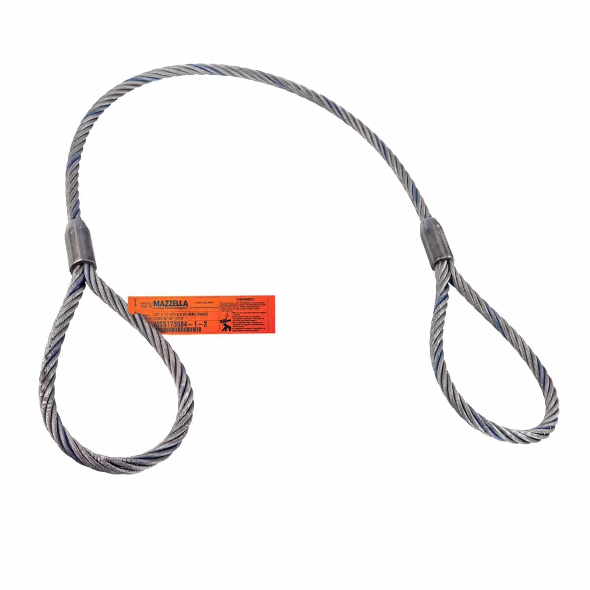
Our in-house proof testing center is used to verify the integrity of the products we manufacture. Every wire rope sling or bridle that we produce includes an OSHA appropriate DuraTag stating: size, working load limit, number of legs, and angle chart graphics. Our assemblies are manufactured to the highest standards by trained professionals. All of our wire rope slings are made from USA made products. The most common wire rope sling type is the eye and eye single leg.
Tway Lifting Products manufactures wire rope slings, spreaders and assemblies from ¼”-2”. We stock fittings and components that allow us to produce a full range of wire rope slings multi-leg assemblies, crane boom support cables, and bridge crane hoist ropes.
Our in-house proof testing center is used to verify the integrity of the products we manufacture. Every wire rope sling or bridle that we produce includes an OSHA appropriate DuraTag stating: size, working load limit, number of legs, and angle chart graphics. Our assemblies are manufactured to the highest standards by trained professionals. All of our wire rope slings are made from USA made products. The most common wire rope sling type is the eye and eye single leg.

Stock up on every variety of steel wire rods at the Alibaba metalworking store. Our listings feature wholesale steel rods from a network of dependable Chinese manufacturing partners. If you need to source steel rods for construction projects, you"ll find products that are robust and durable. And if you need welding rods, they are easy to find via our search engine. Track down the eye splice wire rope you need at affordable prices at Alibaba.com.
What can you do with the steel wire rods available from Alibaba"s wholesale store? One common use for steel rods is in the welding sector. Steel works well as a welding rod material thanks to its high ductility, meaning that welds are relatively strong and long-lasting. Choose a low carbon rod and you"ll be all set for successful welds in industrial settings and workshops alike. However, steel wire also has applications beyond welding. You can use it as wiring in electronic circuits and power distribution systems and it works especially well in high temperature settings as armored cabling. Find the ideal eye splice wire rope for every industrial use at Alibaba.com.
Steel wire rods also have applications in everyday life. For example, you can use coils of steel wire to construct fences and barriers both inside and outside homes. It"s a common material in agricultural businesses thanks to its toughness and resistance to oxidation. Use it to create reinforcement cages, enclosures for equipment, or add it to concrete to add extra strength where it really matters. From welding to concrete reinforcement, eye splice wire rope will always find a use. And whether you need small batches or huge bulk orders, our metallic materials catalog is the ideal place to look.
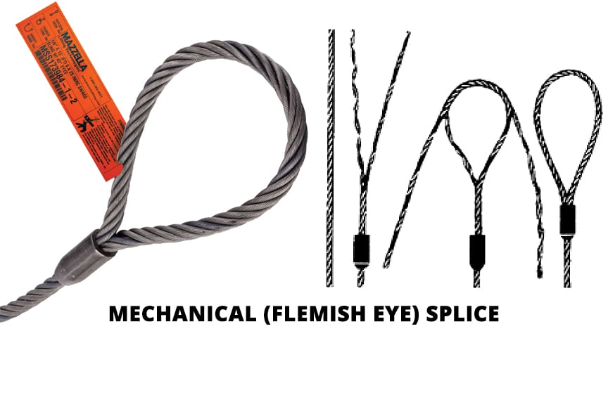
The most popular splicing method. Its safety relies mainly on the craftsmanship of the correct splicing method. The sleeve’s function is to secure the strand ends around the rope body. Steel sleeves are very rugged and withstand a lot of abuse. The flemish eye splice is the preferred method in the construction industry and for most industrial sling applications.
Loop end terminations for rotation resistant- and non-rotating ropes, and for ropes having more than 6 strands, require either aluminum- or loop-back steel sleeves.

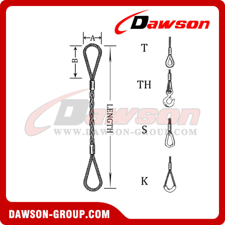
As a rigger or end-user of wire rope, it’s important to understand the types of terminations, or treatments, that can be used at the ends of a length of wire rope. These terminations are usually made by forming an eye or attaching a fitting, and are designed to be a permanent end termination on the wire rope where it connects to the load.
Wire rope is an extremely versatile mechanical device that can be used to help support and move an object or load. In the lifting and rigging industries, wire rope is attached to a crane or hoist and fitted with swivels, shackles or hooks to attach to a load and move it in a controlled matter. It can also be used to lift and lower elevators, or as a means of support for suspension bridges or towers.
In this article, we’ll explain what some of the following terms mean and how the can be used to terminate the end of a wire rope cable:Wire rope sockets—spelter sockets, swaged sockets, and wedge sockets
When you understand the construction and specifications of the wire rope you need, as well as the right type of end termination you need, you’ll be able to select the best performing and longest-lasting wire rope for the job at hand.
There are essentially two techniques that can be used to create a termination on a length of wire rope or cable:You can form an eye, or loop, in the wire rope
Eyes, or loops, can be created at one end of a length of wire rope by using a mechanical splice with a swaged sleeve, a hand-tucked splice, or wire rope clips.
A swaged socket is applied to the end of a wire rope cable and is then forced into place using special dies and a hydraulic machine called a swager. When properly applied with the correct sized fitting, swaged sockets have an efficiency rating of 100% of the breaking strength of the rope.
A poured socket, commonly referred to as a spelter socket, attaches a termination fitting onto the end of a wire rope cable by pouring molten zinc or resin into a socket that then hardens and holds the fitting onto the end of the cable.
Due to the rigidity of this type of termination, the wires of the rope are subject to fatigue where the wires enter the socket, if the poured socket is subject to constant vibration.
Wedge sockets secure the rope to the end attachment by passing it around a grooved, wedge-shaped piece of steel and pulling it down under load into the bowl of the fixture.
Wedge sockets are popular because they can be installed in field and adjusted in field – providing 80% efficiency of rope breaking strength. Wedge sockets are popular in applications where the wire rope may be subjected to abuse and abrasion—particularly in construction and mining applications.
Wire rope clips can be used to form a load bearing eye at the end of a cable or wire rope, or to connect two cables together with a lap splice. Wire rope clips are popular because they can be installed in the field and provide 80% efficiency of the rope breaking strength.
However, the use of wire rope clips is heavily regulated by ASME B30.26 Rigging Hardware. When using wire rope clips, the end user must account for the following:When using U-bolt wire rope clips, the saddle shall be placed on the live end of the wire rope, with the U-bolt on the dead-end side—NEVER SADDLE A DEAD HORSE!
After installation, the connection shall be loaded to at least the expected working load. After unloading, the wire rope clips shall be re-tightened to the torque specifications of the manufacturer or a Qualified Person.
This type of wire rope clip is essentially a U-bolt, two nuts, and a metal base (saddle) that can be made from forged steel or cast iron. Careful consideration and attention must be given to the way U-bolt type wire rope clips are installed.
The base of the wire rope clip is made from forged steel. Forged clips are heated and hammered into the desired shape—resulting in a consistent grain structure in the steel. Forged wire rope clips are used for critical, heavy-duty, overhead loads such as winch lines, crane hoist lines, support lines, guy lines, towing lines, tie downs, scaffolds, etc.
Malleable wire rope clips are used for making eye termination assemblies only with right regular lay wire rope and only for light duty uses with small applied loads, such as hand rails, fencing, guard rails, etc. The base of the wire rope clips is made from malleable cast iron, which may fracture under heavy use and does not have the desirable metal properties of steel, or the beneficial grain structure that a forged base has.
Double saddle wire rope clips consist of two saddles, each with a leg, and two nuts—one used on the top and one on the bottom. Double saddle wire rope clips can be used in either direction, so they take the guesswork out during installation when applying to the live end and the dead end of a piece of wire rope.
An eye splice may be used to terminate the loose end of a wire rope when forming a loop. The strands of the end of a wire rope are unwound and then the wire is bent around, and the unwrapped strands are then weaved back into the wire rope to form an eye.
A Flemish eye splice is created when the wire rope is opened, and the strands are laid out into two parts. The two strands are looped in opposite directions and then laid back together—forming an eye, or loop, at one end of the wire rope cable. The strands are then rolled back around the rope body and a metal sleeve fitting is slipped over the splice and swaged using hydraulic machinery. This splicing method provides the most efficient use of rope capacity and is highly economical.
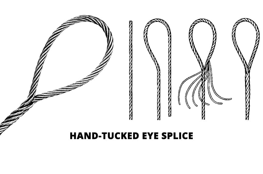
A hand tucked splice is formed when the shorter “dead” end is tucked into the longer “live” end of the wire rope—forming an eye. These types of splices allow for easy inspection of the wire rope wires and strands.
When the end of a rope is turned back and formed into an eye, a thimble is often used to keep the shape of the eye, prevent the rope from being crushed, and keep the rope from being bent at a diameter smaller than the rope manufacturer’s recommendations.
The table below will explain the efficiencies of the different types of wire rope end terminations for both independent wire rope core (IWRC) and fiber core (FC) wire rope configurations. Rope efficiency is described as the ratio of a wire rope’s actual breaking strength and the aggregate strength of all individual wires tested separately—usually expressed as a percentage.IWRCFC
*Spelter sockets in smaller rope sizes (usually less than 7/16”) may not always develop 100% efficiency and are not recommended by some rope manufacturers.
When you need to order a replacement wire rope, understanding the right type of end termination will help to make sure you get a direct replacement rope so you can get your project back on track. We hope this article gives you a better understanding of terms related to sockets, wire rope clips, and eye splices and that you understand what type of end termination may be best for your application.
At Mazzella, we offer all different kinds of wire rope from all of the leading manufacturers. We sell the highest-quality domestic and non-domestic rigging products because product quality and operating safety go hand-in-hand. We have one of the largest and most complete inventories of both domestic and non-domestic rigging and lifting products to suit your lifting needs.
In stricter senses, the term wire rope refers to a diameter larger than 9.5mm (3⁄8in), with smaller gauges designated cable or cords.wrought iron wires were used, but today steel is the main material used for wire ropes.
Historically, wire rope evolved from wrought iron chains, which had a record of mechanical failure. While flaws in chain links or solid steel bars can lead to catastrophic failure, flaws in the wires making up a steel cable are less critical as the other wires easily take up the load. While friction between the individual wires and strands causes wear over the life of the rope, it also helps to compensate for minor failures in the short run.
Wire ropes were developed starting with mining hoist applications in the 1830s. Wire ropes are used dynamically for lifting and hoisting in cranes and elevators, and for transmission of mechanical power. Wire rope is also used to transmit force in mechanisms, such as a Bowden cable or the control surfaces of an airplane connected to levers and pedals in the cockpit. Only aircraft cables have WSC (wire strand core). Also, aircraft cables are available in smaller diameters than wire rope. For example, aircraft cables are available in 1.2mm (3⁄64in) diameter while most wire ropes begin at a 6.4mm (1⁄4in) diameter.suspension bridges or as guy wires to support towers. An aerial tramway relies on wire rope to support and move cargo overhead.

The Flemish eye splice is popular. The rugged and durable sleeves secure the ends of the strands around the body of wire rope slings. For the construction industry and the majority of industrial sling applications, this is the preferred method.
Flemish eye splice is only performed on six-strand ropes. Loop end terminations used for non- and rotation-resistant wire ropes, as well as ropes with more than six strands, require aluminum or turn-back steel sleeves. If the sleeves are made from regular carbon or aluminum metal, an electrochemical reaction between the two metals has the potential to speed up deterioration. This can be accelerated if the slings are used in corrosive environments or saltwater.
The fabrication of this splice involves forming a loop eye and pressing an aluminum sleeve over both rope parts. As for strength, this is dependent on the pressed sleeve’s integrity. For non-rotating rope types, as well as 8-, 9-, and 10-strand ropes, thimbles at the ends are typically requested.
This method is almost identical to the aluminum turn back splice with the exception that it is fabricated with steel sleeves of a somewhat smaller diameter. Also available in stainless steel, this termination can be used on stainless steel ropes of a larger diameter. With this method, the rope loops back into a swaged sleeve, forming a permanent load-bearing bond between the two parts of the rope.
For the termination on these wire rope slings, the rope inserts into the fitting bore, followed by being swaged onto the rope. This is the preferred method for open and closed sockets, buttons, and threaded studs and to attach a load hook directly onto the rope. This method works great for all rope constructions, and it produces a high-efficiency bond.
Some people do not believe that spelter socket terminations are true sling fittings. Traditionally, this type of end termination was used to determine the breaking strength of wire rope slings. Considered 100 percent of the true actual rope strength, all other end terminations are compared to spelter sockets.
Let me take you back a few years to discuss sling changes. Three underlying causes for this evolution are reliability, handleability, and cost. OSHA, in 1971, left sling capacity up to the users. Tables listed; construction of rope, type of Eye end connections, rope diameter, and how used (choker, etc.) for the user to ponder capacity!
The picture above presents a poor rigging practice. The “fold-back” Aluma-Grip fabricated splice forming the sling’s eye is unreliable (yellow arrow) and not recommended for hoisting, but still in use.
Why? When fabricating a fold-back eye splice, 100% of the eye strength is dependent on the wall thickness of the fitting, and its clamping force. These non-steel fittings are softer, and when swaged, they are less likely to hold a uniform wall thickness, thus strength. Examinations show cracks, voids, and wall thickness to a sliver! This method is less expensive but lacks reliability.
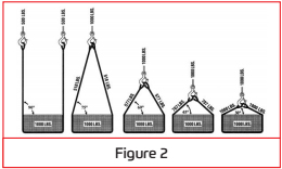
The Flemish eye, Molly Hogan, or a Farmer’s eye – all synonyms – are preferred, reliable. To construct, untwist (open) the rope with three strands on one side and three strands plus the core on the opposite. The loop develops (eye) when the “two-sides” are re-formed back together. A sling with a thimble is shown in Fig. 2. Reliable is achieved when the sleeve is swaged up to 300 tons pressure.
Tests show the frictional grip of the strands, under tension, will hold up to 22% of the breaking strength of the rope before failure. Even with no fitting applied, that would equal a 5 to 1 factor of safety. Today, the two-sides are cut off at the “crotch” of the eye. A tapered steel sleeve is slipped over the crotch and crimped to hold the eye, to as much as 90% of the ropes breaking strength, keeping the ends locked.
Back in the day, the two-sides were closed to the crotch; the excess is pulled over the rope and re-laid together, forming a “pigtail.” Fig. 3. Wire rope clips were used to secure the live end to the pigtail dead-end, locking the eye just as the swaged fitting today. Thus, a rigger, on the tailgate of his truck, in 15 minutes, could fabricate a completed “field splice.” A thimble clip-on was available.
A field splice is a term I first heard around the Post Korean Wartime era. It meant precisely that. The sling, being very adaptable, were used for many types of work – in the “field.” A guy would form an eye in a wire rope, when and where it was needed! Those eyes were hand tuck, wire rope clips, wedged sockets, Flemish eyes, and pored zinc spelter sockets. These slings were used to pull equipment, haul logs, tie-down trucks, and lift loads.
We realized, there was little consistency of technique or any quality control procedures in place. The resulting accidents exposed numerous errors. Pulling a tree could tolerate some mistakes (perhaps), but deaths, lifting construction material, was unacceptable. Field-splice became a dirty word!
“The times they are a-changing boys.” And how! The building is faster, higher, heavier, and more costly. People in the field are erecting towers, build skyscrapers, or replacing heat exchangers. It’s just too expensive to be sitting around, whittling away on wood or forming make-shift eye splices from used rope, ah, the good ole days.
So, the “certified sling” with a capacity tag attached to the rope, load tested to 150% of capacity, and the quality control program of the fabricator was born. (But the kids should know, some of us could do it right – out in the field.)
This invention relates to sleeve splices for wire ropes or cables and methods of making them, the object of the invention being to provide an improved sleeve splice securing the full strength of the rope while simple and cheap to manufacture.
The invention is especially applicable in connection with rope eyes formed by bending back the dead end of the rope to form the eye and securing this to the live rope by compressing or swaging a sleeve over the two portions of the rope, but the broader features of the invention are applicable, also, in connection with splicing wire ropes together in other relations and for other purposes.
For a full understanding of the invention a detailed description will now be given, in connection with the accompanying drawings forming a part of this specification, of a rope eye with sleeve splice embodying the invention in a preferred form and made by the preferred method, and the features forming the invention will then be specifically pointed out in the claims.
In the drawings: Figure 1 is a side view of the rope eye with the sleeve enclosing the dead end and live rope before compression or swaging of the sleeve; Figure 2 shows a completed eye; Figure 3 is an enlarged illustrative cross section through the sleeve and ropes of Figure 2, this Figure 3 showing a fiber center rope; Figure 4 is a diagram illustrating the die action for compressing or swaging the sleeve about the ropes, the dies being shown in a preferred form and in position for pressing; Figure 5 is a similar view showing the second step in the pressing operation, from which further action of the dies compresses the sleeve and ropes into the form like that shown in Figures 2 and 3; Figure 6 is an enlarged view similar to Figure 4, with a rope having a wire strand center; and Figure 7 is a view illustrating the sleeve, ropes and dies of Figure 6 in the completed form of the splice.
Referring to the drawings, the rope eye is shown as of a common form consisting of the live rope A bent to form the eye and with the dead end B compressed or swaged with the rope A in the sleeve C, the eye being shown as having the common thimble or lining D, although this may be omitted and the eye may be of any other form.
The preferred method of forming the splice by compressing or swaging the sleeve dead end, and live rope together is by compression of the sleeve and ropes within the suitably formed dies E, F, illustrated in Figures 4 and 5, either with or without turning of the sleeve between pressing steps.
The live rope is first passed through the sleeve and bent to form the eye, the strands of the dead end B of Figures 1 to 3 are then spread by opening the dead end and then pushed through the sleeve so as to enclose partially or fully, and preferably only partially, the live rope A, as shown in Figure 1, and the sleeve is then compressed under heavy pressure over the live rope A and the spread strands of the dead end B to form the sleeve splice as shown in Figures 2 and 3. In this die compression, the ropes and sleeve will pass through the intermediate form illustrated in Figure 5 to the final form of Figure 3, securing a uniform and strong grip of the sleeve on the ropes with the live rope running straight through the sleeve.
The ends of the sleeve are formed at such an angle that the taper of the sleeve ends is substantially retained in the pressing operation and the sleeve reduced by flowing of the metal so as to elongate the sleeve while retaining this angle in the splice, as shown in the completed thimble splice of Figure 2. The bore of the sleeve is thus straight and uniform and grips the ropes throughout and the rope moves smoothly with no sharp shoulders on the sleeve. For this result the ends of the thimble are preferably formed with an angle of 400 to 75°, depending upon conditions of the metal and the swaging pressure and method used.
In Figure 3, the live rope A is shown complete with its fiber center I at the lower right of the sleeve and the strands and fibrous center 2 of the dead end B are spread around the top left side and bottom of the live rope, but it will be understood that this is only illustrative and a cross section of the complete splice will show different arrangements of the rope, dead end strands and fiber, depending upon the character of the rope and the swaging pressure and method of swaging used. The only important feature is that the live rope A shall not be bent In the sleeve, but shall be central to the eye and straight through the sleeve, so that the pull on the live rope is in a straight line, thus securing the full strength of the rope. With the die pressing shown and heavy pressure, the metal of the sleeve flows into the voids within the sleeve and the sleeve may be thickened slightly at the right and left sides, as shown in Figure 7, which latter feature in the method shown aids in compacting the splice, but is not essential, depending upon the swaging action employed.
In Figures 6 and 7 I have illustrated the thimble splice eye with a rope having a wire rope center, Figure 6 showing the live rope G with the rope center 3, the strands of the dead end H spread around the top of the live rope G and the seven strands of the wire rope center 4 of the dead end spread between the live rope and dead end. It will be understood that this is only illustrative and will vary under different conditions.
The invention is not to be limited to the details of the construction and method illustrated, but modifications may be made in the splice and method of making it within the claims.
What I claim is: 1. A sleeve splice of an end of wire rope to an unopened live section of wire rope which comprises said section of unopened rope passing straight through an open end sleeve of straight circular bore with said rope end opened and the strands introduced into the sleeve about said unopened section, said sleeve being die pressed upon said section and strands so that its external diameter is reduced, the sleeve is elongated and the walls thereof are thickened.
2. A wire rope eye splice which comprises an unopened live section of wire rope passing straight through an open end sleeve of uniform bore with the helically laid wire strands of the dead end of the rope separated and introduced into the sleeve in a form spread about the helically laid wire strands of said unopened section, said sleeve being die pressed upon said section and strands so that the sleeve is reduced in external diameter, elongated and the walls thereof are thickened.
3. A sleeve splice of an end of wire rope to an unopened live section of wire rope which comprises said section of unopened rope passing straight through an open end sleeve of uniform circular bore with its ends tapered at an angle between 400 and 750 to the axis of said sleeve, and with said end of wire rope opened and the strands thereof introduced into the sleeve about said unopened section, said sleeve being die pressed throughout its length upon said section and strands so that the sleeve is reduced in external diameter, is elongated and the walls thereof are thickened.
4. A method of forming a wire rope splice which comprises opening the end of one of a plurality of rope members, spreading the wire strands of the opened member about the helically laid wire strands of another unopened rope member, and compressing a sleeve of uniform circular bore upon said spread wire strands and unopened rope member under such pressure as to compress the spread strands about a major portion of the peripheral surface of said unopened member.
5. A method of forming a wire rope eye splice which comprises passing a section of wire rope through an open end metal sleeve having a straight bore of uniform size, opening the dead end of the wire rope to separate the strands thereof and introducing said strands into said sleeve in a form spread about the unopened live section of wire rope, and compressing the sleeve about said live section and spread strands with sufficient pressure to reduce the diameter of the sleeve, thicken the walls thereof and compress said spread strands about a major portion of the peripheral surface of said live section.
6. A method of forming a wire rope splice whicI comprises passing an unopened section of one of a pair of rope member through an open end sleeve having a uniform circular bore with its open ends tapered at an angle between 400 and 750 to the axis of said sleeve, opening an end of the other of said rope members to spread the wire strands thereof and introducing said spread wire strands into the sleeve in a position distributed about the helically laid strands of said unopened member, and compressing the sleeve throughout its length to reduce its diameter and produce elongation thereof and to compress the spread strands about a major portion of the surface of the unopened rope member.


 8613371530291