
wire rope failure analysis factory

Due to the wide variety of service conditions for wire ropes, they are susceptible to many types of inadequacies and failures. It is important for consumers to frequently inspect wire ropes for signs of wear and fatigue. Wire ropes will inevitably fail if not used according to manufacturing limitations or when routine inspections for fatigue and wear are not properly performed. Eventually, all wire ropes are removed from service when they meet established discard criteria.

Unfortunately, many phone calls into ITI Field Services begins this way, “We have had an incident with a wire rope and we believe the rope failed. How do we determine the cause of failure?”
Fortunately, the calls come in because wire rope users want to determine cause of failure in an effort to improve their crane, rigging and lifting activities.
A wire rope distributor received a hoist rope and sockets from a rubber-tired gantry. The rope and sockets were returned by the customer who believed the rope and sockets failed. The distributor hired ITI Field Services to conduct an analysis on the rope and sockets to determine the cause of the failure and to produce written documentation.
Based on the findings of the examination, fatigue-type breaks in the wires indicated that the wire rope lost significant strength due to vibration. There was no indication that the rope was overloaded. The poured sockets showed no evidence of abnormalities in the pouring method, wire zinc bonding length or the materials used in the speltering process. The conclusion of the inspection is that rope failed due to fatigue.
Wire rope examination is just one of the many services that is offered by ITI Field Services. ITI has some of the most highly-regarded subject-matter experts in the crane and rigging industry with experience in performance evaluations, litigation, accident investigations, manual development and critical lift planning reviews.
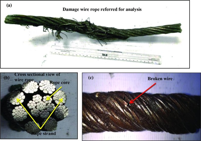
A failure analysis of a broken multi strand 71mm steel wire rope used in the main towing winch was carried out. The wire rope was failed during a bollard pull test. The wire rope was a new one and had failed during the first use. The wire rope was in IWRC/ RHO 6X41 constructions. Fig.1 shows the typical cross section of the wire rope. The failure investigation is performed by chemical and metallurgical examinations.
(ii) the uniformity and cleanliness of the microstructure of the rope steel and the effect of microstructure on crack initiation and propagation, and
1) Chemical analysis of steel wire rope is presented in Table 1. The analysis showed that it is made of high carbon steel corresponding to AISI 1074 grade, and galvanized with zinc to resist corrosion.
2) The microstructure observed under optical microscope and is shown in Figs. 2. It was typical of a drawn ferrite–pearlitic steel wire with heavily cold worked micro structure. Further examination of microstructure of the failed wires did not indicate any sign of metallurgical problems such as de- carburized layer, nonmetallic inclusions, or martensite formation. In addition, the wires were free from any sort of corrosion and pitting. Therefore, corrosion had no role in the failure of wires.
4) Table 3 represents the tensile values of the wire. The result indicates relatively less value comparing the metallographic results and the mill test certificate supplied by the Client. Figs. 3 showing Stress- Strain during tensile testing of the wire
The high hardness values, chemical composition, and the pearlitic structure of wires indicating that this is a type of extra extra improved plow steel (EEIPS) grade wire ropes. These types of wires have typically higher load-bearing capacity as compared with other grades. They are considered as heavy-duty wire ropes. The minimum tensile strength of EEIPS is 2160 N/mm2. (Ref. API Spec 9A)
5) The fractured ends of group of wires were visually inspected. Majority of wires failed in shear, and the remaining had cup-and-cone fracture, some of which are shown in Fig. 4.
Fractographs of broken wires in the form of cup and cone and shear are shown in Fig. 5 and Fig.6. Tensile overload fracture occurs when the axial load exceeds the breaking strength of the wires. This type of fracture usually appears in ductile manner, either in the form of cup and cone or in shear mode. In the former case, there is a reduction at the fracture which is called necking, whereas in the case of the latter, fracture surface is inclined at 45degree to the wire axis. In both cases, ductile dimple formations are clearly observed and confirm the tensile overloading of wires.
Every wire rope failure will be accompanied by a certain number of tensile over load breaks. The fact that tensile overload wire breaks can be found therefore necessarily mean that the rope failed because of an overload. The rope might have been weakened by fatigue breaks. The remaining wires were then no longer able to support the load, leading to tensile overload failures of these remaining wires.
Only if the metallic area of the tensile overload breaks and shear breaks combined is much higher than 50% of the wire rope’s metallic cross section is it likely that the rope failed because of an overload.
Shear breaks are caused by axial loads combined with perpendicular compression of the wire. Their break surface is inclined at about 45degree to the wire axis. The wire will fail in shear at a lower axial load than the pure tensile over load.
If a steel wire rope breaks as a consequence of jumping a layer or being wedged in, a majority of wires will exhibit the typical 45degree break surface.
In the instant case the wire rope was failed at 100 Ton or even less. As the breaking load of the wire rope is 353 Tons, there is no reason for a tensile over load breaks in an axial direction and that too considering the fact that the wire rope was failed during a bollard pull test. Fig. 7 shows the maximum stress generations in the wire rope at 100 Ton under normal bollard pull test. More over the metallurgical investigation is also not suggesting for any factors that fostering an axial overload failure.
The failure of the wire rope was studied in detail. In order to investigate the problem metallurgical and mechanical post failure analyses were performed. The wire rope was made of AISI 1074 grade steel, and it was a type of EEIPS. The microstructure was composed of severely deformed and elongated ferrite–pearlite, and no other phase formation or nonmetallic inclusions could be detected. The morphologies of fractured surfaces indicated that the wires were mainly failed in shear mode and few in tensile mode. Owing to galvanized coating, the wires were free from corrosion.
The tensile strength of the wire material is less than the required value. The required tensile strength of EEIPS is 2160 N/mm2 and the obtained value is 2059 N/mm2. But this factor is not a reason for the current failure of the wire rope. The said point is substantiated by the following:
It is concluded that the wire rope was failed due to shear breaks. Shear breaks were caused by high axial loads combined with perpendicular compression of the wire. It is worthwhile to note that the rope was failed in its first usage. The shear break is linked to the lapses during the installation/ spooling of the wire rope.
b) Lack of pretension of lower rope layers during spooling. In the absence of proper pretension the upper layers might be pulled in between the lower layers during loading.
c) Under high tension, the rope tends to be as round as possible. With no load, a rope can be deformed and flattened much easily. Highly tensioned upper layers will therefore severely damage loose (and therefore vulnerable) lower layers.
Wire rope is often referred to as a "machine" because when bends the individual slide relative to each other. For this reason wire ropes on running rigging require lubrication. Proper lubrication retards wear and corrosion. A wire rope can have hundreds of separate wires in its cross section. Each wire was made separately at what was possibly a different day. For this reason it is unlikely that a "local" weak area can exist due to a manufacturing error. This characteristic of wire ropes also allows an un-fractured adjacent section to be tested to estimate the pre-fracture strength of a wire rope. Wire ropes fracture because they are loaded in excess of their strength, but their strength can be reduced due to such things as wear, corrosion, or local damage. It is possible for a system to create a load which is greatly in excess of that which was originally intended.

In 1998, a crane load line broke while lifting the south topside module of the Petronius platform, dropping the module into the Gulf of Mexico. The cost was estimated to be around 116 million US dollars. Since 1999 more than 60 people have been killed as a result of wire ropes breaking and more than 65 associated injuries.
Not many people appreciate that there are literally thousands of wire rope designs, most of which can be put into a specific category. According to BS ISO 4309 2010 there are currently more than 25 categories of crane wire rope, each with differing characteristics and also different discard criteria. Deterioration can be measured, counted or calculated and the wire rope eventually taken out of service based on sophisticated discard criteria published in chosen standards, codes of practice or users handbooks.
Unfortunately there is no simple answer to either of these questions. All wire ropes will eventually break due to corrosion, wear or fatigue even if they are maintained and used properly. Unpredictable wire rope failures will inevitably occur, quite often when you least expect it if the discard criteria is ignored, or those using the equipment are ignorant of it.
James Dawes of Topeka, Illinois, was killed in 2008 after being struck by the boom of a Link-Belt crane; the accident was caused by the boom hoist wire rope breaking. The crane rope had been inspected, but a report said that the inspector failed to reject the rope showing a high number of visible wire breaks. Premature or unexpected wire rope failures can also be attributed to poor manufacture, incorrect handling and storage, poor installation technique, poor selection or fitting of its termination, infrequent or inadequate inspection and poor maintenance. Of course there is always the possibility that mechanical damage can occur and this is usually attributed to human error.
It is necessary, particularly during offshore operations that frequent inspections are carried out over the whole length of the working part of all steel wire ropes. The frequency of inspections should be based on the severity of use and risk assessment and particular attention should be paid to the critical areas of the wire rope; areas that are frequently running over sheaves, compensating sheaves and the rope termination to name a few.
If a wire rope has not been subjected to an abnormal environmental condition such as excessive heat, chemical attack or any corrosive solution and it has not been the victim of any form of mechanical damage, then trained operatives and inspectors can reasonably predict the length of time the steel wire rope is likely to last. That prediction, of course, will be dependent on the knowledge and experience of those making it coupled with known facts about the rope, its current condition and the application it is running on. The Inspector should be aware of the previous rope’s history, capacities of loads and the reeving systems employed together with the frequency of use etc.
Various standards and codes of practice have been written by recognized bodies and institutes based on the experience of experts or representatives of corporate organizations who have a vested interest. These standards do offer guidance on when a wire rope should be removed from service based on wear, abrasion and fatigue amongst others things, but none of these standards have any legal status except when they are called up by contract. Indeed they can all be supported or overturned in a court of law by an expert.
The users handbook, or more importantly the safe use instructions do have legal status. In many parts of the world these days, suppliers of cranes or any machinery for that matter, issue safe use instructions with new equipment. Modern applications employ modern wire rope and, in some cases, sheaves and pulleys that are made with materials other than steel. Original equipment manufacturers of such applications may impose discard criteria for the wire rope that is stricter than those in chosen standards. By law the user must follow manufacturers’ instructions.
Wire ropes will deteriorate much more quickly if they go dry and are allowed to remain in that condition. Tests have proven that a dry rope will lose up to 60 % of its expected life if it is not re-lubricated. There are differing schools of thought as to how wire rope should be lubricated. Some believe that a thin lubricant should be applied using a paintbrush. It is thought that this method allows the lubricant to penetrate. Experience has proven however, that thin penetrative lubricants will easily drain away or fly off in hot climates.
Another school of thought, and the one I stand on, is that grease should be pressure lubricated into the rope. This method, if applied properly, will ensure that the grease penetrates the rope pushing out the old lubricant with it and any possible corrosive agents such as salt water and sand. Any lubricant that is used must be compatible with the type that was applied previously and it is a good idea to consider the environment as well.
In any event, wire ropes usually announce that they are about to break. A series of individual wire breaks can be heard. These are likely to go on over several seconds and continuing for up to ten minutes before ultimate failure. Therefore, if operatives understand the warning signals, expensive incidents could be avoided.
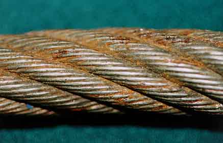
Figure 2 shows two pieces of the same rope, the bottom portion quite clearly shows a progression of wire breaks. The operator was able to put the load down before disaster struck. The root cause of this fault was core deterioration brought about by internal corrosion.
To answer the other question on accountability, the list is extensive. Usually the first suspect is the wire rope manufacturer and that may be where the problem lies, but very often that is not the case. What if you were supplied the wrong rope for the application? Maybe you ordered the wrong rope or your buyer bought it from a cheap unapproved manufacturing source.
Perhaps your supplier is responsible, maybe he provided you with a rope that was produced to the wrong specifications. Would you know the difference? Perhaps you were sold a rope that had been stored in the suppliers or manufactures stock for a number of years and, whilst it was there, it hadn’t been properly maintained. Maybe the rope had been badly handled or installed incorrectly. The list of possibilities is endless.
In 1999 a ropeway in the French Alps snapped causing 21 deaths. In 2003, a ropeway wire rope snapped and 7 people died and a further 42 were injured. In 2007 a crane wire rope snapped at New Delhi’s metro, the entire structure tumbled down crushing workers underneath, six people were killed and 13 more were injured. In 2009 26 people were killed and 5 people were injured when a rope failed in a mine and a further 6 people were injured when a lift rope broke inside London’s Tower Bridge.
If you find yourself in the unfortunate situation after the unthinkable premature failure of a wire rope, then you might like to know that there are independent analytical services capable of determining probable cause. One of these is Doncaster Analytical Services Ltd (DAS), they have an independent metallurgical laboratory providing factual analysis and testing of wire rope for any reason (contact Mr Shui Lee, Technical Director, Tel +44(0)1302 556063, email: shui.lee@doncasteranalyticalservices. com).
You do not need a wire rope to fail in order to learn. Careful analysis of discarded ropes can also give you valuable information about your application, the way it operates, and the rope you have been using.
Based on this information, a trained, skilled and experienced inspector will be able to advise on a better crane or wire rope design, or to an improvement in maintenance procedures and safety.
![]()
Wire ropes, pulleys, counterweights, and connecting systems are used for auto tensioning of contact wires of electric railways. A wire rope in one such auto tensioning system suffered premature failure. Failure investigation revealed fatigue cracks initiating at nonmetallic inclusions near the surface of individual wire strands in the rope. The inclusions were identified as Al-Ca-Ti silicates in a large number of stringers, and some oxide and nitride inclusions were also found. The wire used in the rope did not conform to the composition specified for AISI 316 grade steel, nor did it satisfy the minimum tensile strength requirements. Failure...
Wire ropes with diamond beads used in machines for cutting blocks of stone are subjected to fatigue, contact fatigue, corrosion and corrosion-fatigue loads in an aggressive environment.
As shown in Figure 1 1-3, multi-wire machines for cutting blocks of stone are made of two structural main components: the supporting structure, fixed with flanged bolts to the ground, (1 in Figure 1), and a vertical moving part 4 (Figure 1). Several wire ropes with diamond beads are put in motion by a driven drum (2 and 7 in Figure 1). The tensioning mechanical system (9 in Figure 1) allows to apply a tension to the wire ropes with diamond beads while the machine is cutting the stone blocks. Several pulleys guide the wire ropes; up to 80 wire ropes can be used and mounted in parallel on the structural component 4 and on several pulleys. the motorized drum is the component 3 in Figure 1 and a three-phase asynchronous electric motor is mounted on the machine and puts the drum and the wires in motion. Wire ropes with diamond beads are the cutting tools of the machine and the designer must take care of such components when mounted on the machine. It is well known that the structural behavior of steel wire ropes, composed of several strands, is complex and multiaxial stresses, along with contact fretting stresses, must be managed. Working conditions of the wire ropes have to be strictly controlled and checked periodically.
Notwithstanding there are many literature references on the study of the damage of wire ropes, few research references can be found in the literature, as far as the author knows, that would allow to understand their structural behavior in terms of damage or failure analyses 4-11. In 4 Authors report a study on the diamond wire cutting of concrete materials. Wire cutting with diamond technique was used in the United States until the early 1980s and allowed to cut reinforced concrete structures, regardless of thickness and reinforcement content. In 5 an innovative and optimized design of automatic adjustment system for beaded rope of new diamond wire sawing machine is reported, while in 6 the mechanics of sawing granite with diamond wire is considered. Research on cutting performance optimization of diamond wire saw is deepened in 7. In these papers the structural design of the wire rope with diamond beads is introduced and the mechanical structure and control of the adjusting device of the diamond wire saw are described. Working parameters are transmitted via wireless signals to achieve remote control. Mechanics of cutting procedure is deepened and mechanical simulation and optimization models of the wires with diamond beads are proposed. Many references are available on the study of wire ropes without diamond beads 8-11; such references allow to understand the mechanisms of failure in case of absence of the beads: unfortunately, the Author pf this paper found that the structural fatigue and corrosion-contact-fatigue behavior of the wire rope is highly influenced by the presence of the diamond beads.
This paper contains the results of the observation of surface damage of wires used in multi-wire machines for cutting blocks of stone and the optical analysis of beads for 2.35 mm cables. The cables are used as a support for pearls equipped with diamond inserts for cutting stones (beads) (Figure 2).
The samples were taken from wire ropes having 2,35 mm diameter. The wire rope is composed of 7 strands wires, one of which is located at the centre of the wire rope (“soul”). Each strand contains 7 single wires having 0.3 mm wires diameter (Figure 5).
The study was conducted by means of microscopic analysis, X-ray microtomography and tests with penetrating liquids. For the first, two Leica stereoscopic microscopes (MZ 75 with magnification up to 50x and microscope with magnification up to 40x) with digital camera (Canon Powershot S50 and Canon EOS 1100D) and an Opto-De monofocal optical microscope with magnifications were used up to 400x with Motic 2300 USB 2.0 acquisition camera. A new stereoscopic optical microscope mod. ZENITH SZM-4500 Trinocular Zoom 7x-45x with additional lens 2x mod, ST-087 2x for 14x-90x magnification and a variable double LED illuminator mod. ZENITH CL-31 with double jointed self-standing arm. The images were taken with a USB micro-camera Mod. OPTIKAM B-3 complete with optics. The effectiveness of the protective plastic coating was evaluated by pouring liquids (blue ink) on the cable.
Significant sections of the beaded wire as shown in Figure 4 were investigated. Section X.1 was not considered but we focused on the evaluation of the centering of the cable in the beads. The sections were obtained using a metallographic cutting machine.
The wire ropes with beads were also observed by unwinding the strands and the core both by opening the individual strands and by releasing the individual wires before proceeding with the observation. Figure 5 shows two examples of preparation of a stranded cable and single strands and wires.
Figure 6 shows two examples of the cracked surfaces of the wires. Those cracks greatly affect the fatigue resistance of the whole wire rope with beads.
To evaluate the effect of the environment on the wire rope, tests were carried out with penetrating liquids (blue ink). Liquids were poured onto the flexed sample to simulate operational behavior. Figure 8 shows the penetrating liquids experimental test.
Contact between the wire rope and the beads was observed (Figure 9). Beads and the wire rope are made of different materials and this might cause corrosion of the wires in the rope, along with contact fatigue damage.
The wire ropes studied in this work are designed with low fatigue resistance safety factors (2-3). Previous analyses helped in reaching some useful conclusions 3-10.
Detachment of brass or zinc coatings which, being thin, are unable to adhere to the wire at the cracks. Causes can also be found in the straightening operation and incorrect handling of the ropes.
Observations and analysis of the damaged wire ropes allowed to highlight that the beads have no continuous side surface and at the discontinuity the finish is very poor. Moreover the insertion of the diamond chips is not uniform. The insertion of the splinters causes localized lifting of the material. This could cause premature detachment of some of them. Wire ropes are mechanical components that work in a complex stress state with contact loads, wear, corrosion and fatigue resistance problems. The presence of the diamond beads is a further stress concentration, with corrosion and contact wear fatigue problems if the beads come into contact with the wire rope during assembly or in working condition.
The advice is to product wire ropes with beads in which the centering of the cable with respect to the bead is carefully controlled. No contact between rope and bead should occur. According to the results and observations this is the most important advice for producer of the ropes with diamond beads.
This paper reports the failure analysis of the damage mechanisms of wire ropes with diamond beads mounted in machines for cutting stones. Wire ropes with diamond bead are cutting tools subjected to fatigue, corrosion-contact-fatigue stresses. Cracks and defects are present in the strands of the wire ropes, generated during the production process: these cracks are further sources of stress concentrations. The observation at the microscope, and the penetrating liquids analyses, highlighted that the most important advice to give to the producer of the wire ropes with diamond beads is to product components in which the centering of the cable with respect to the bead is carefully controlled.
Pedrini, G., Baragetti, S., 2016, “Multi-wire machine for cutting blocks of stone and wire tensioning device”, International Patent n° WO 2016/071936A1.
Bangju Wei et al, 2020, “Innovative and optimized design of automatic adjustment system for beaded rope of new diamond wire sawing machine”IOP Conf. Ser.: Mater. Sci. Eng. 892 012078.
Janusz Stefan Konstanty, 2021,”The mechanics of sawing granite with diamond wire”, The International Journal of Advanced Manufacturing Technology (2021) 116:2591–2597.
Liu S., Sun Y.Send mail to Sun Y., Jiang X., Kang Y., 2022, “A new MFL imaging and quantitative nondestructive evaluation method in wire rope defect detection”, Mechanical Systems and Signal Processing, vol. 163.
Peng, Y., Wang, G., Zhu, Z., Jiang, F., Chen, G., 2021, “Effect of low temperature on tribological characteristics and wear mechanism of wire rope”, Tribology International, vol. 164.
Wang et Ali, 2021, “Tribological properties and residual strength of wire rope with different strands during the interlayer-transition stage”, vol. 480-481, Wear.
Bassir Y., et Ali, 2021, “Comparative study of the service life of a central core and a helical strand constituting the same rope”, vol. 247, Engineering Structures.

Metallographic and Vickers 500gr micro-hardness results identified the wires as cold drawn and exhibited converted Rockwell C values of 54 to 56 HRC, typical for this grade of wire rope. The approximate ultimate tensile strength (UTS) of the steel wires – estimated from the hardness results, was 307 ksi UTS.
Visual examinations found numerous locations with heavy deformation (crushing) on the outer strand wires that also exhibited fatigue fractures. The observed crushing deformation likely resulted from: a) simple overload events, b) uneven drum winding with heavy loads, or c) shock/dynamic loading that locally deformed the outer wires in the strands.
The wire deformation introduced laps and seams that are favorable fatigue initiation sites. Most fractures were observed at the deformed wire locations. Repeated bending during operation after wire deformation propagated numerous fatigue cracks – resulting in catastrophic overload failure after the load bearing capability of the wire rope was reduced due to the numerous fractured wires.

Many wire-rope manufacturers and machine designers are under the impression that the significant stress in a wire rope is the tensile stress, or possibly the stress due to tension and bending. This paper proves by mathematical analysis that by far the greatest stress in a wire rope results from Hertz contact stresses at points of contact of wire-on-wire, and asserts that the usual mode of failure of a wire rope is fretting-fatigue initiated at such points of contact. Design relationships based on these concepts should be of great value to designers who use wire rope.
A failure analysis of a broken multi strand wire rope from an offshore platform crane was performed. The wire rope was operated for less than 5 years. The wire consists of seven strands, one central strand and six strands around it. The diameter of the small wires was about 0.78-0.94 mm and the larger wires was a round of 1.52 - 1.78 mm. The large size wires were found fractured by cyclic torsional stresses as characterized by the presence of fatigue cracking originating from the outer surface of the wire. Meanwhile the smaller wires were fractured in a ductile manner under excessive load after the larger wire broken out due to the fatigue mechanism.
Shamsudin S.R., Harun, M., Anuar M.A.M.S., Yazid,H., Mazlee, M.N. Failure Investigation on Rusty Mesh Strainer of Petrochemical Plant,. Advanced Materials Research. 795 (2013): 488-491.

High-carbon steel wire ropes are used for various high-load-bearing applications. They achieve tensile strength of the order of 2 GPa owing to a combination of fine pearlitic microstructure and work hardening during the drawing process. Despite these high strength levels, they can fail during service due to either manufacturing defects or service abuse. In this study, failure analysis of main hoist steel wire rope used in a basic oxygen furnace (BOF) was carried out. Several locations of the wire rope showed unprecedented microstructural degradation. The presence of surface martensite with transverse cracks was observed in severely abraded wires. Some locations of the rope revealed fusion of adjacent wires with increased interlamellar spacing of pearlite and formation of divorced pearlite in heat-affected and fusion zones, respectively. A significant variation in hardness across the wire rope was noted due to these in-service microstructural changes. Such macroscopic and microstructural deterioration has not been reported in open literature. Detailed failure analysis of the wire rope along with a novel theory explaining the mechanisms of such microstructural degradation is presented herein. This study confirms that the wire rope suffered premature damage due to improper lubrication during service that led to direct metal-to-metal contact, associated friction, abrasion, and fusion of wires. Excessive friction and abrasion of wires subsequently led to fatigue of some of the wires, as manifested by square or crown breaks and striation marks.


 8613371530291