
wire rope failure types factory

In 1998, a crane load line broke while lifting the south topside module of the Petronius platform, dropping the module into the Gulf of Mexico. The cost was estimated to be around 116 million US dollars. Since 1999 more than 60 people have been killed as a result of wire ropes breaking and more than 65 associated injuries.
Not many people appreciate that there are literally thousands of wire rope designs, most of which can be put into a specific category. According to BS ISO 4309 2010 there are currently more than 25 categories of crane wire rope, each with differing characteristics and also different discard criteria. Deterioration can be measured, counted or calculated and the wire rope eventually taken out of service based on sophisticated discard criteria published in chosen standards, codes of practice or users handbooks.
Unfortunately there is no simple answer to either of these questions. All wire ropes will eventually break due to corrosion, wear or fatigue even if they are maintained and used properly. Unpredictable wire rope failures will inevitably occur, quite often when you least expect it if the discard criteria is ignored, or those using the equipment are ignorant of it.
James Dawes of Topeka, Illinois, was killed in 2008 after being struck by the boom of a Link-Belt crane; the accident was caused by the boom hoist wire rope breaking. The crane rope had been inspected, but a report said that the inspector failed to reject the rope showing a high number of visible wire breaks. Premature or unexpected wire rope failures can also be attributed to poor manufacture, incorrect handling and storage, poor installation technique, poor selection or fitting of its termination, infrequent or inadequate inspection and poor maintenance. Of course there is always the possibility that mechanical damage can occur and this is usually attributed to human error.
It is necessary, particularly during offshore operations that frequent inspections are carried out over the whole length of the working part of all steel wire ropes. The frequency of inspections should be based on the severity of use and risk assessment and particular attention should be paid to the critical areas of the wire rope; areas that are frequently running over sheaves, compensating sheaves and the rope termination to name a few.
If a wire rope has not been subjected to an abnormal environmental condition such as excessive heat, chemical attack or any corrosive solution and it has not been the victim of any form of mechanical damage, then trained operatives and inspectors can reasonably predict the length of time the steel wire rope is likely to last. That prediction, of course, will be dependent on the knowledge and experience of those making it coupled with known facts about the rope, its current condition and the application it is running on. The Inspector should be aware of the previous rope’s history, capacities of loads and the reeving systems employed together with the frequency of use etc.
Various standards and codes of practice have been written by recognized bodies and institutes based on the experience of experts or representatives of corporate organizations who have a vested interest. These standards do offer guidance on when a wire rope should be removed from service based on wear, abrasion and fatigue amongst others things, but none of these standards have any legal status except when they are called up by contract. Indeed they can all be supported or overturned in a court of law by an expert.
The users handbook, or more importantly the safe use instructions do have legal status. In many parts of the world these days, suppliers of cranes or any machinery for that matter, issue safe use instructions with new equipment. Modern applications employ modern wire rope and, in some cases, sheaves and pulleys that are made with materials other than steel. Original equipment manufacturers of such applications may impose discard criteria for the wire rope that is stricter than those in chosen standards. By law the user must follow manufacturers’ instructions.
Wire ropes will deteriorate much more quickly if they go dry and are allowed to remain in that condition. Tests have proven that a dry rope will lose up to 60 % of its expected life if it is not re-lubricated. There are differing schools of thought as to how wire rope should be lubricated. Some believe that a thin lubricant should be applied using a paintbrush. It is thought that this method allows the lubricant to penetrate. Experience has proven however, that thin penetrative lubricants will easily drain away or fly off in hot climates.
Another school of thought, and the one I stand on, is that grease should be pressure lubricated into the rope. This method, if applied properly, will ensure that the grease penetrates the rope pushing out the old lubricant with it and any possible corrosive agents such as salt water and sand. Any lubricant that is used must be compatible with the type that was applied previously and it is a good idea to consider the environment as well.
In any event, wire ropes usually announce that they are about to break. A series of individual wire breaks can be heard. These are likely to go on over several seconds and continuing for up to ten minutes before ultimate failure. Therefore, if operatives understand the warning signals, expensive incidents could be avoided.
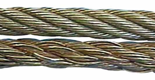
Figure 2 shows two pieces of the same rope, the bottom portion quite clearly shows a progression of wire breaks. The operator was able to put the load down before disaster struck. The root cause of this fault was core deterioration brought about by internal corrosion.
To answer the other question on accountability, the list is extensive. Usually the first suspect is the wire rope manufacturer and that may be where the problem lies, but very often that is not the case. What if you were supplied the wrong rope for the application? Maybe you ordered the wrong rope or your buyer bought it from a cheap unapproved manufacturing source.
Perhaps your supplier is responsible, maybe he provided you with a rope that was produced to the wrong specifications. Would you know the difference? Perhaps you were sold a rope that had been stored in the suppliers or manufactures stock for a number of years and, whilst it was there, it hadn’t been properly maintained. Maybe the rope had been badly handled or installed incorrectly. The list of possibilities is endless.
In 1999 a ropeway in the French Alps snapped causing 21 deaths. In 2003, a ropeway wire rope snapped and 7 people died and a further 42 were injured. In 2007 a crane wire rope snapped at New Delhi’s metro, the entire structure tumbled down crushing workers underneath, six people were killed and 13 more were injured. In 2009 26 people were killed and 5 people were injured when a rope failed in a mine and a further 6 people were injured when a lift rope broke inside London’s Tower Bridge.
If you find yourself in the unfortunate situation after the unthinkable premature failure of a wire rope, then you might like to know that there are independent analytical services capable of determining probable cause. One of these is Doncaster Analytical Services Ltd (DAS), they have an independent metallurgical laboratory providing factual analysis and testing of wire rope for any reason (contact Mr Shui Lee, Technical Director, Tel +44(0)1302 556063, email: shui.lee@doncasteranalyticalservices. com).
You do not need a wire rope to fail in order to learn. Careful analysis of discarded ropes can also give you valuable information about your application, the way it operates, and the rope you have been using.
Based on this information, a trained, skilled and experienced inspector will be able to advise on a better crane or wire rope design, or to an improvement in maintenance procedures and safety.
Due to the wide variety of service conditions for wire ropes, they are susceptible to many types of inadequacies and failures. It is important for consumers to frequently inspect wire ropes for signs of wear and fatigue. Wire ropes will inevitably fail if not used according to manufacturing limitations or when routine inspections for fatigue and wear are not properly performed. Eventually, all wire ropes are removed from service when they meet established discard criteria.
A failure analysis of a broken multi strand 71mm steel wire rope used in the main towing winch was carried out. The wire rope was failed during a bollard pull test. The wire rope was a new one and had failed during the first use. The wire rope was in IWRC/ RHO 6X41 constructions. Fig.1 shows the typical cross section of the wire rope. The failure investigation is performed by chemical and metallurgical examinations.
(ii) the uniformity and cleanliness of the microstructure of the rope steel and the effect of microstructure on crack initiation and propagation, and
1) Chemical analysis of steel wire rope is presented in Table 1. The analysis showed that it is made of high carbon steel corresponding to AISI 1074 grade, and galvanized with zinc to resist corrosion.
2) The microstructure observed under optical microscope and is shown in Figs. 2. It was typical of a drawn ferrite–pearlitic steel wire with heavily cold worked micro structure. Further examination of microstructure of the failed wires did not indicate any sign of metallurgical problems such as de- carburized layer, nonmetallic inclusions, or martensite formation. In addition, the wires were free from any sort of corrosion and pitting. Therefore, corrosion had no role in the failure of wires.
4) Table 3 represents the tensile values of the wire. The result indicates relatively less value comparing the metallographic results and the mill test certificate supplied by the Client. Figs. 3 showing Stress- Strain during tensile testing of the wire
The high hardness values, chemical composition, and the pearlitic structure of wires indicating that this is a type of extra extra improved plow steel (EEIPS) grade wire ropes. These types of wires have typically higher load-bearing capacity as compared with other grades. They are considered as heavy-duty wire ropes. The minimum tensile strength of EEIPS is 2160 N/mm2. (Ref. API Spec 9A)
5) The fractured ends of group of wires were visually inspected. Majority of wires failed in shear, and the remaining had cup-and-cone fracture, some of which are shown in Fig. 4.
Fractographs of broken wires in the form of cup and cone and shear are shown in Fig. 5 and Fig.6. Tensile overload fracture occurs when the axial load exceeds the breaking strength of the wires. This type of fracture usually appears in ductile manner, either in the form of cup and cone or in shear mode. In the former case, there is a reduction at the fracture which is called necking, whereas in the case of the latter, fracture surface is inclined at 45degree to the wire axis. In both cases, ductile dimple formations are clearly observed and confirm the tensile overloading of wires.
Every wire rope failure will be accompanied by a certain number of tensile over load breaks. The fact that tensile overload wire breaks can be found therefore necessarily mean that the rope failed because of an overload. The rope might have been weakened by fatigue breaks. The remaining wires were then no longer able to support the load, leading to tensile overload failures of these remaining wires.
Only if the metallic area of the tensile overload breaks and shear breaks combined is much higher than 50% of the wire rope’s metallic cross section is it likely that the rope failed because of an overload.
Shear breaks are caused by axial loads combined with perpendicular compression of the wire. Their break surface is inclined at about 45degree to the wire axis. The wire will fail in shear at a lower axial load than the pure tensile over load.
If a steel wire rope breaks as a consequence of jumping a layer or being wedged in, a majority of wires will exhibit the typical 45degree break surface.
In the instant case the wire rope was failed at 100 Ton or even less. As the breaking load of the wire rope is 353 Tons, there is no reason for a tensile over load breaks in an axial direction and that too considering the fact that the wire rope was failed during a bollard pull test. Fig. 7 shows the maximum stress generations in the wire rope at 100 Ton under normal bollard pull test. More over the metallurgical investigation is also not suggesting for any factors that fostering an axial overload failure.
The failure of the wire rope was studied in detail. In order to investigate the problem metallurgical and mechanical post failure analyses were performed. The wire rope was made of AISI 1074 grade steel, and it was a type of EEIPS. The microstructure was composed of severely deformed and elongated ferrite–pearlite, and no other phase formation or nonmetallic inclusions could be detected. The morphologies of fractured surfaces indicated that the wires were mainly failed in shear mode and few in tensile mode. Owing to galvanized coating, the wires were free from corrosion.
The tensile strength of the wire material is less than the required value. The required tensile strength of EEIPS is 2160 N/mm2 and the obtained value is 2059 N/mm2. But this factor is not a reason for the current failure of the wire rope. The said point is substantiated by the following:
It is concluded that the wire rope was failed due to shear breaks. Shear breaks were caused by high axial loads combined with perpendicular compression of the wire. It is worthwhile to note that the rope was failed in its first usage. The shear break is linked to the lapses during the installation/ spooling of the wire rope.
b) Lack of pretension of lower rope layers during spooling. In the absence of proper pretension the upper layers might be pulled in between the lower layers during loading.
c) Under high tension, the rope tends to be as round as possible. With no load, a rope can be deformed and flattened much easily. Highly tensioned upper layers will therefore severely damage loose (and therefore vulnerable) lower layers.

Unfortunately, many phone calls into ITI Field Services begins this way, “We have had an incident with a wire rope and we believe the rope failed. How do we determine the cause of failure?”
Fortunately, the calls come in because wire rope users want to determine cause of failure in an effort to improve their crane, rigging and lifting activities.
A wire rope distributor received a hoist rope and sockets from a rubber-tired gantry. The rope and sockets were returned by the customer who believed the rope and sockets failed. The distributor hired ITI Field Services to conduct an analysis on the rope and sockets to determine the cause of the failure and to produce written documentation.
Based on the findings of the examination, fatigue-type breaks in the wires indicated that the wire rope lost significant strength due to vibration. There was no indication that the rope was overloaded. The poured sockets showed no evidence of abnormalities in the pouring method, wire zinc bonding length or the materials used in the speltering process. The conclusion of the inspection is that rope failed due to fatigue.
Wire rope examination is just one of the many services that is offered by ITI Field Services. ITI has some of the most highly-regarded subject-matter experts in the crane and rigging industry with experience in performance evaluations, litigation, accident investigations, manual development and critical lift planning reviews.
Wire ropes are largely used in marine environment or for rigging purposes. They receive considerable loads and thus suffer a great deal of mechanical damage throughout their service life. Moreover, research has shown that the major cause of wire rope failure is excessive deterioration and corrosion, lack of maintenance and inspection, and wrong usage resulting in early discarding, reduced safety and replacement cost increase.
Sometimes damage can be easily detected, while in other cases fractured wires may occur on the inside. Hence, wire ropes should be inspected and maintained by the right person (competent person assigned by the company), to assure they’re in perfect condition. Regular inspectionsensure high rope performance, long service lifetime , safety of personnel and equipment, and reduced operating costs.
All ropes (synthetic, high modulus and wire ropes) should be inspected before and after an operation. This guideline ensures maximum safety for both a ship’s personnel and equipment. Even though it’s difficult to determine the exact service life span of ropes, there is a way to have a more precise estimation about their efficient lifecycle. Calculating the exact time ropes have been in use (e.g mooring time, mooring conditions, weather and tidal conditions) is the answer. All in all, rope inspections should occur at least once a year.
Inspecting wire ropes in particular, comes with great responsibility. Inspection results should be recorded, and any defects noticed have to be reported and addressed properly. Some defects can be repaired, while in some cases replacing a wire rope is inevitable.
Periodical inspections ofvessel deck equipment is also crucial for maintaining the good condition of wire ropes. The condition of the drum, chocks, bitts, rollers, sheaves, cable clamps and other end fittings, affect the rope’s performance, threads and cords. Make sure to mark these parts during your overall inspection.
In order to help marine officers and staff conduct successful wire rope inspections – and keep an up-to-date record of them – we have created an inspection solution that helps in maintaining and monitoring a ship’s ropes and deck equipment.
When calculating mass using F = Minimum Breaking Force, according to the wire rope’s diameter, you can determine the Minimum Breaking Massand therefore the wire’s max strength. When calculating mass using F = Safe Load according to the wire rope’s diameter, you can determine the Safe Load Mass,which is the advised load for this rope diameter.
The strands of a wire rope absorb the majority of the tensile force applied on the rope. Their design and manufacturing standards affect the level of fatigue resistance and resistance to abrasion. An easy way to understand which rope design is suitable for each purpose, is the wire rope classification.
Wire ropes are classified according to the number of strands in each construction and the number of wires in each strand. For example, a classification of 6X19 means that a wire rope of this type always has six strands, but its wires could be 15-26 per strand. This is because 19 is not the exact number of wires, but the classification of a wire number range.
Visual inspections are a common and fast way to assess wire rope condition. Both the standard and rotation resistant wire rope inspectionprocesscomply with the same four steps of examination. A ship’s crew can perform them as follows:
Steel wire rope distortion is obvious in most cases and can easily be identified by the inspector or the ship‘s crew. It usually occurs if load is suddenly applied or abruptly released (shock loading), or even if swift torque is forcefully induced.
Although not all of these deformations make the rope absolutely dangerous to use, they all may cause ropes to wear unevenly in time. This means inspections should take place more often, and distorted ropes should be handled with caution.
The rag and visual inspection is a good method for regular inspection intervals. The inspector pulls a rag along the rope trying to find broken wire cords. If the rug gets snagged by the rope, the inspector has to stop and assess the wire rope’s condition. Extreme caution should be exercised during the visual inspection, and under no circumstances should this method be the only one used to inspect wire ropes.
Tip: When you encounter a protruding wire end, bend it back and forth manually, until it separates from the wire. This will protect neighboring wires from wearing out.
Diameter reduction is a critical factor in steel wire rope wear and if not properly taken care of, it can result in rope breakage. Excessive abrasion, loss of core mass, corrosion or inner wire failure are all factors that contribute to diameter reduction.
To get an accurate measurement of the rope’s diameter, measure the rope at three different points at least 5 feet apart. Take the average of these three measurements to determine the true diameter.
Any measurements showing a reduction of ⅓ or more, indicate that a replacement should follow without delay. A diameter reduction of less than 1/3 still requires attention, and the inspector or the ship’s crew should be on guard in the next scheduled wire rope inspection.
Failure from abrasion or corrosion is a result of deficient deck equipment inspection or insufficient wire rope lubrication respectively. Internal corrosive damage is more difficult to identify than any other types of degradation. In most cases, the damage has progressed more than the external signs suggest.
Wire rope storage plays a significant role in the rope’s operation life.Wire rope corrosion and pitting can be avoided if ropes are safely stored in a clean, cool, dry and well-ventilated place. Steel wire ropes should not by any means rest on the floor, and should be protected from water, dust or any chemical fumes. Long term storage requires periodic greasing, turning the reel upside down for preventing grease dripping and possibly re-winding to another reel with larger inner tube diameter.
Wire ropes should be maintained with periodical lubrication. In order to prevent internal corrosion, a pressure lubricator is suggested to be used. In this case, a small amount of grease is used to lubricate the rope internally, while the deck stays grease-clean. Pressure lubricators clean the rope before they grease it so that the new grease enters a clean rope. The type of grease used is very important for maximum protection and greasing efficiency.
Steel wire ropes exposed to dirt, grime and other contaminants, have to be cleaned with a wire brush and petroleum (unless a pressure lubricator is used). Optimal cleaning of wire ropes can extend their service life and guarantee safe operations.
The reeling process is of high importance for the longevity of wire ropes. To protect them from being damaged, it is important that the surface of the drum is clean, smooth and dry. Improper reeling may cause wire-rope strands to spread or get flattened, when in contact with one another, as successive layers are being spooled and upper layers apply pressure on the lower ones.
Katradis S.A. offers a wide range of top quality wire ropes for shipping (mooring and hoisting operations), fishing and construction purposes. Our wire ropes have greater resistance to fatigue, and they distribute tension force equally among the rope strands. They are less likely to kink, providing higher staff safety and assuring operation success.

Wire ropes, pulleys, counterweights, and connecting systems are used for auto tensioning of contact wires of electric railways. A wire rope in one such auto tensioning system suffered premature failure. Failure investigation revealed fatigue cracks initiating at nonmetallic inclusions near the surface of individual wire strands in the rope. The inclusions were identified as Al-Ca-Ti silicates in a large number of stringers, and some oxide and nitride inclusions were also found. The wire used in the rope did not conform to the composition specified for AISI 316 grade steel, nor did it satisfy the minimum tensile strength requirements. Failure...
Wire ropes, pulleys, counterweights, and connecting systems are used for auto tensioning of contact wires of electric railways. A wire rope in one such auto tensioning system suffered premature failure. Failure investigation revealed fatigue cracks initiating at nonmetallic inclusions near the surface of individual wire strands in the rope. The inclusions were identified as Al-Ca-Ti silicates in a large number of stringers, and some oxide and nitride inclusions were also found. The wire used in the rope did not conform to the composition specified for AISI 316 grade steel, nor did it satisfy the minimum tensile strength requirements. Failure...


 8613371530291