
wire rope fleet angle manufacturer

The name LeBus has been around the oil field industry since it was just a blacksmith shop in 1900. LeBus started out by manufacturing speciality tools for the booming west Texas oil fields. Tool pushers and/or owners would see a specific need for a new tool and LeBus would forge the new tools on demand. Soon LeBus was into the manufacturing and selling of fishing tools, drill collars, tool joints and rotary bits. LeBus manufactured the "Eureka Pipe Wrench" and the "Slip Socket Overshot". The common element in each case was the hoisting machinery, specifically the drum and wire rope, which was the main "workhorse" of the drilling rig. LeBus noticed that the wire rope would not lay in a consistent pattern on the drum. This caused undue wear and scrubbing of the wire rope. Something better was on the horizon.
The achievement of even winding on a smooth faced drum is closely related to the magnitude of the D/d ratio, the speed of rotation, load on the rope, and the fleet angle. Of all these factors, the one that exerts perhaps the greatest influence on winding characteristics is the fleet angle.
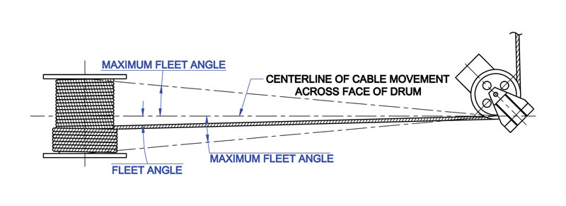
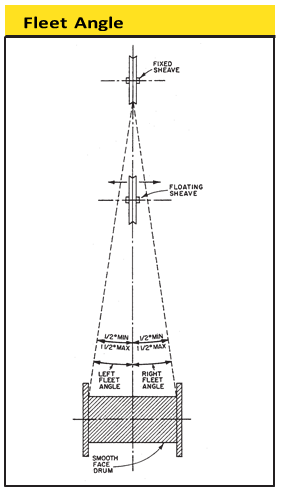
The schematic drawing (Fig. 39) shows an installation where the wire rope runs from a fixed sheave, over a floating sheave, and then on to the surface of a smooth drum. The fleet angle (Fig. 39) may be defined as the included angle between two lines; one line drawn through the middle of the fixed sheave and the drum – and perpendicular to the axis of the drum and a second line drawn from the flange of the drum to the base of the groove in the sheave. (The drum flange represents the farthest position to which the rope can travel across the drum.) There are left and right fleet angles, measured to the left or right of the center line of the sheave, respectively.
It is necessary to restrict the fleet angle on installations where wire rope passes over the lead or fixed sheave and onto a drum. For optimum efficiency and service characteristics, the angle here should not exceed 1 1/2º for a smooth drum, or 2º for a grooved drum. Fleet angles larger than these suggested limits can cause such problems as bad winding on smooth drums, and the rope rubbing against the flanges of the sheave grooves. Larger angles also create situations where there is excessive crushing and abrasion of the rope on the drum. Conversely, small fleet angles – less than 1/2º – should also be avoided since too small an angle will cause the rope to pile up.

Any assembly of steel wires spun into a helical formation, either as a strand or wire rope, when subjected to a tensile load, can extend in three separate phases, depending on the magnitude of the applied load. There are also other factors which produce rope extension which are very small and can normally be ignored.
At the commencement of loading a new rope, extension is created by the bedding down of the assembled wires with a corresponding reduction in overall diameter. This reduction in diameter is accommodated by a lengthening of the helical lay. When sufficiently large bearing areas have been generated on adjacent wires to withstand the circumferential compressive loads, this mechanically created extension ceases and the extension in Phase 2 commences. The Initial Extension of any rope cannot be accurately determined by calculation and has no elastic properties.
The practical value of this characteristic depends upon many factors, the most important being the type and construction of rope, the range of loads and the number and frequency of the cycles of operation. It is not possible to quote exact values for the various constructions of rope in use, but the following approximate values may be employed to give reasonably accurate results.
Following Phase 1, the rope extends in a manner which complies approximately with Hookes Law (stress is proportional to strain) until the Limit of Proportionality or Elastic Limit is reached. It is important to note that wire ropes do not possess a Young’s Modulus of Elasticity, but an ‘apparent’ Modulus of Elasticity can be determined between two fixed loads.
The Modulus of Elasticity also varies with different rope constructions, but generally increases as the cross-sectional area of steel increases. By using the values given, it is possible to make a reasonable estimate of elastic extension, but if greater accuracy is required it is advisable to carry out a modulus test on an actual sample of the rope. As rope users will find it difficult to calculate the actual metallic steel area , the values can be found in the Wire Rope Users Manual or obtained from Bridon Engineering.
The permanent, non-elastic extension of the steel caused by tensile loads exceeding the yield point of the material. If the load exceeds the Limit of Proportionality, the rate of extension will accelerate as the load is increased, until a loading is reached at which continuous extension will commence, causing the wire rope to fracture without any further increase of load.
The coefficient of linear expansion (∝) of steel wire rope is (6.94 x10⁻⁶ per oF) and therefore the change in length of 1 foot of rope produced by a temperature change of t (oF) would be:
Example: What will be the total elongation of a 200 Ft length of 11/8" diameter Blue Strand 6x41 IWRC wire rope at a tension of 20,000 Ibs and with an increase in temperature of 20oF.
In addition to bending stresses experienced by wire ropes operating over sheaves or pulleys, ropes are also subjected to radial pressure as they make contact with the sheave. This pressure sets up shearing stresses in the wires, distorts the rope’s structure and affects the rate of wear of the sheave grooves. When a rope passes over a sheave, the load on the sheave bearing results from the tension in the rope and the angle of rope contact. It is independent of the diameter of the sheave.
Assuming that the rope is supported in a well fitting groove, then the pressure between the rope and the groove is dependent upon the rope tension and diameter but is independent of the arc of contact.
It must be realized that this method of estimation of pressure assumes that the area of contact of the rope in the groove is on the full rope diameter, whereas in fact only the crowns of the outer wires are actually in contact with the groove. It is estimated that the local pressures at these contact points may be as high as five times those calculated.
If the pressure is high, the compressive strength of the material in the groove may be insufficient to prevent excessive wear and indentation and this in turn will damage the outer wires of the rope and effect its working life. As with bending stresses, stresses due to radial pressure increase as the diameter of the sheave decreases.
Although high bending stresses generally call for the use of flexible rope constructions having relatively small diameter outer wires, these have less ability to withstand heavy pressures than do the larger wires in the less flexible constructions. If the calculated pressures are too high for the particular material chosen for the sheaves or drums or indentations are being experienced, consideration should be given to an increase in sheave or drum diameter. Such a modification would not only reduce the groove pressure, but would also improve the fatigue life of the rope.
The pressure of the rope against the sheave also causes distortion and flattening of the rope structure. This can be controlled by using sheaves with the correct groove profile which, for general purposes, suggests a recommended groove diameter of nominal rope diameter +6%. The profile at the bottom of the groove should be circular over an angle of approximately 120o, and the angle of flare between the sides of the sheave should be approximately 52o.
Bend fatigue testing of ropes usually consists of cycling a length of rope over a sheave while the rope is under a constant tension. As part of its ongoing development program BRIDON has tested literally thousands of ropes in this manner over the years on its in-house own design bend testing equipment.
Through this work, BRIDON has been able to compare the effects of rope construction, tensile strength, lay direction, sheave size, groove profile and tensile loading on bend fatigue performance under ideal operating conditions. At the same time it has been possible to compare rope life to discard criteria (e.g. as laid down in ISO 4309) with that to complete failure of the rope, i.e. to the point where the rope has been unable to sustain the load any longer. As part of the exercise, it has also been possible to establish the residual breaking strength of the rope at discard level of deterioration.
What needs to be recognized, however, is that very few ropes operate under these controlled operating conditions, making it very difficult to use this base information when attempting to predict rope life under other conditions. Other influencing factors, such as dynamic loading, differential loads in the cycle, fleet angle, reeving arrangement, type of spooling on the drum, change in rope direction, sheave alignment, sheave size and groove profile, can have an equally dramatic effect on rope performance.
However, the benefit of such testing can be particularly helpful to the rope manufacturer when developing new or improving existing products. If designers or operators of equipment are seeking optimum rope performance or regard bending fatigue life as a key factor in the operation of equipment, such information can be provided by BRIDON for guidance purposes.
Under certain circumstances it may be necessary to use a swivel in a lifting system to prevent rotation of the load. This is typically done for employee safety considerations. It is possible however, that the use of a swivel will have an adverse affect on rope performance and may in some cases damage the wire rope.
There are many types of accessories available that incorporate different types and degrees of rotation preventing swivels. The swivel may be either an independent accessory or an integral part of a lifting device such as a crane block with a swivel hook. A typical independent accessory is a ball bearing anti- friction swivel. There are also headache balls with swivel hooks. The type of swivel that causes the most concern from the standpoint of the wire rope is the independent anti-friction swivel that attaches directly to the rope. The purpose of using a swivel in a lifting system is to prevent rotation of the load. This then allows the wire rope to rotate. Excessive rope rotation can damage a wire rope.
To assist in determining whether or not a swivel should be used in the lifting system, the following recommendations should be considered. It must also be recognized that the rotation characteristics of different types and constructions of wire rope vary considerably. The following types and constructions of wire rope are grouped according to their rotation characteristics.
Wire rope constructions having very high rotation characteristics should not be used with a swivel under any circumstances. These rope constructions will rotate excessively with one end free to rotate and the rope will unlay and distort and be easily damaged with a loss of rope breaking force.
Wire rope constructions having high rotation characteristics when used in single part reeving may require a swivel in the system to prevent rotation in certain operating conditions. However, this should be done only when employee safety is the issue.
These rope constructions when used in a reeving system with one end free to rotate will have a high level of rotation. This will cause the rope to unlay to some degree and distortion of the rope will occur.
The ropes in this Group are designed with an inner rope that is laid in the opposite direction to the outer strands to provide a medium resistance to rotation. Ropes with medium rotation characteristics are used with a swivel in single part reeving applications. However, a swivel is not recommended for multiple part hoisting applications or in any application where the swivel is not necessary for safety reasons. If it is necessary to use a swivel the rope must be operating within the design factor of 5, must not be shock loaded and must be inspected daily by a qualified person for distortion.
It should be noted that if a swivel is used in conjunction with Group 3a ropes, rope service life might be reduced due to increased internal wear between the outer strands and the inner rope.
Wire ropes having low rotation characteristics used in either single or multiple part reeving may be used with a swivel. The reason for this is that the ropes will exhibit very little, if any, rotation when used at the proper design factor. Application parameters such as a fleet angle may induce turn into a wire rope that can be relieved by the use of a swivel. However, if the application does not induce any turn into the rope or if a swivel is not beneficial to the performance of the rope the swivel may not be necessary.
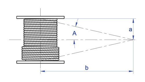
Of all the factors which have some influence on the winding of a rope on a smooth drum, the fleet angle, arguably, has the greatest effect. Fleet angle is usually defined as the included angle between two lines, one which extends from a fixed sheave to the flange of a drum and the other which extends from the same fixed sheave to the drum in a line perpendicular to the axis of the drum. (See illustration).
If the drum incorporates helical grooving, the helix angle of the groove needs to be added or subtracted from the fleet angle as described above to determine the actual fleet angle experienced by the rope.
When spooling rope onto a drum it is generally recommended that the fleet angle is limited to between 0.5O and 2.5O. If the fleet angle is too small, i.e. less than 0.5O, the rope will tend to pile up at the drum flange and fail to return across the drum. In this situation, the problem may be alleviated by introducing a ‘kicker’ device or by increasing the fleet angle through the introduction of a sheave or spooling mechanism.
If the rope is allowed to pile up it will eventually roll away from the flange creating a shock load in both the rope and the structure of the mechanism, an undesirable and unsafe operating condition. Excessively high fleet angles will return the rope across the drum prematurely, creating gaps between wraps of rope close to the flanges as well as increasing the pressure on the rope at the cross-over positions.
Even where helical grooving is provided, large fleet angles will inevitably result in localized areas of mechanical damage as the wires ‘pluck’ against each other. This is often referred to as ‘interference’ but the amount can be reduced by selecting a Langs lay rope if the reeving allows.
The “interference” effect can also be reduced by employing a Dyform rope which offers a much smoother exterior surface than conventional rope constructions. Floating sheaves or specially designed fleet angle compensating devices may also be employed to reduce the fleet angle effect.
Where a fleet angle exists as the rope enters a sheave, it initially makes contact with the sheave flange. As the rope continues to pass through the sheave it moves down the flange until it sits in the bottom of the groove. In doing so, even when under tension, the rope will actually roll as well as slide. As a result of the rolling action the rope is twisted, i.e. turn is induced into or out of the rope, either shortening or lengthening the lay length of the outer layer of strands. As the fleet angle increases so does the amount of twist.
To reduce the amount of twist to an acceptable level the fleet angle should be limited to 2.5O for grooved drums and 1.5O for plain drums and when using Rotation Resistant, ropes the fleet angle should be limited to 1.5O. However, for some crane and hoist applications it is recognized that for practical reasons it is not always possible to comply with these general recommendations, in which case the rope life could be affected.
The problem of torsional instability in crane hoist ropes would not exist if the ropes could be perfectly torque balanced under load. The torque generated in a wire rope under load is usually directly related to the applied load by a constant ‘torque factor’. For a given rope construction the torque factor can be expressed as a proportion of the rope diameter and this has been done below.
Variation with rope construction is relatively small and hence the scope for dramatically changing the stability of a hoisting system is limited. Nevertheless the choice of the correct rope can have a deciding influence, especially in systems which are operating close to the critical limit. It should be noted that the rope torque referred to here is purely that due to tensile loading. No account is taken of the possible residual torque due, for example, to rope manufacture or installation procedures.
Torsional Stability and the Cabling Graph (see page 78) are two methods which can be used to determine torsional stability or the tendency of the rope to cable. The torque factors quoted on page 79 are approximate maximum values for the particular constructions. To calculate the torque value for a particular rope size multiply by the nominal rope diameter. Example: for 20mm dia. Dyform 34LR at 20% of minimum breaking force:
The torsional characteristics of wire rope will have the effect of causing angular displacement of a sheave block when used in multi-fall reeving arrangements. The formula below gives a good approximation under such arrangements.
The preceding equations are all relative to a simple two part reeving. For more complex systems a similar approach may be used if account is taken of the different spacing of the ropes.
Even Number of Falls Note: For hoisting arrangements in which the rope falls are not parallel an average rope spacing should be used. Uneven Number of Falls
The equations assume that rope is torque-free in the noload condition, therefore, induced torque during or immediately after installation will adversely influence the calculated effect.
The above data assumes a constant torque value which is a valid assumption for a new rope. Wear and usage can have a significant effect on the torque value but practical work shows that under such circumstances the torque value will diminish, thus improving the stability of the arrangement.
Assuming a pedestal crane working on two falls is roped with 20mm diameter DYFORM 34LR and the bottom block carries a sheave of 360mm diameter with the falls parallel:
If the rope is new (worst condition) and no account is taken of block weight and friction then angular displacement for a height of lift of 30 meters is given by sin è = (4 000 . 30 . 0.152)
You may know the importance of fleet angles, but do you know the best ways to correct them? Cris Seidenather, managing director of Lebus International Engineers, explains how...
When spooling wire rope onto a drum, it is necessary for the rope to come onto the drum at a very slight angle, just enough to encourage each wrap to sit tidily next to the previous wrap, and for each layer to ride cleanly onto the layer beneath.
In fact, apart from the design of the drum itself, this angle – the fleet angle – is the most significant factor in the behaviour of a spooling system.
The fleet angle is defined as the largest angle of the rope between the first sheave and the drum flange, relative to the centre line of the drum. With all types of drum, the rope is subject to a fleet angle which directly influences its behaviour and impacts on its service life. If the fleet angle is too big, the wire will tend to pull away from the flange as the layer changes. It will want to spool towards the centre and so leave gaps. Gaps mean ragged spooling, which means (at best) excessive rope wear, or (at worst) snagging, catastrophic system failure and physical danger to all those around.
If the fleet angle is too small, the rope may not pull away from the flange soon enough. It will pile up on the flange for, perhaps, two or three wraps and then bang down with considerable force, damaging the rope and the equipment. Again, catastrophic failure and personal injury is a real threat.
Ideally, the fleet angle should be between 0.25 and 1.25 degrees. This is not an absolute rule of physics; it depends on the rope construction. Nor has it been calculated mathematically. Rather, it has been learned from years of experience. While some wire rope experts may cite slightly different numbers, this is the range that Lebus recommends, and we believe we have at least as much experience as anyone when it comes to multi-layer spooling since inventing the original Lebus counterbalanced spooling system in the 1950s.
The fleet angle can be varied by moving the first sheave closer to or further away from the drum. If the sheave is too close to the drum, the fleet angle will be calculated at greater than 1.25 degrees; if it is too far away, the fleet angle will be less than 0.25 degrees.
In general the distance between sheave and drum should be at least 20 times the width of the drum. Ideally a ratio of 23:1 works very well, we have found. Thus, the larger the drum, the further away the sheave needs to be to keep the fleet angle between 0.25 and 1.25 degrees.
It is not always possible, however, to achieve the optimum fleet angle. For example, there are massive winching systems at the top of mountain cable car systems, often housed in compact machinery sheds. There is often no space to rig a sheave the requisite distance from the drum, and so an alternative for how to reduce the fleet angle must implemented.
For just such cases two additional spooling devices are available. One is a fleet angle compensator, which is driven automatically by the rope tension. The other is a level winder that is mechanically driven. Both offer a solution to guide the cable along the drum between flanges, but each has its advantages and disadvantages.
The fleet angle compensator (FAC) is driven by the movement of the wire rope as it goes through the crossover sections of the drum. As the rope winds or unwinds, the FAC shaft slowly oscillates, allowing its sheave to slide back and forth across the shaft to maintain an optimum fleet angle and guide the rope smoothly onto the drum.
Certain operating conditions are necessary for the Lebus fleet angle compensator to function properly. The rope must go from the drum over the compensator sheave with a minimum contact angle of 60 degrees to a fixed point such as a fairlead or fixed sheave. To avoid excessive angles of the rope on the sheaves, the minimum distance between the fairlead (fixed sheave) and the compensator sheave must be at least six times the drum width. If spooling in multiple layers, the drum must have Lebus-style parallel grooving. For a single layer, helical (screw thread) grooving will also work. As always, there must be sufficient tension on the cable during the spooling operation. We recommend that minimum tension should be 1-2% of the wire rope’s breaking load.
There are three primary advantages of the Lebus fleet angle compensator. First, there is no mechanical connection between the drum and the compensator. Second, installation is easy and quick. And third, it is completely automatic and, after initial adjustments when the rope is first spooled onto the drum, only a minimum of maintenance is necessary.
A mechanical level winder comprises a main shaft (the lead screw) with helical screw grooving along which the rope feeder travels. The rope feeder housing includes two vertical roller bars and one horizontal roller or, alternatively, a wire rope sheave. The lateral movement of the housing is generated by a chain drive sprocket ratio between drum and lead screw, as shown in the image. The automatic level winder fitted is designed and engineered to be compatible with the grooving on the drum. Perfect, controlled spooling is guaranteed regardless the number of layers and slight changes in wire rope size.
The level winder unit – also sometimes called level wind pay-on gear – must be installed in front of the drum in line with the first fixed sheave when using the vertical rollers to guide the wire rope.
The level winder is engineered to be compatible with the parallel grooving on the drum. It is adjusted for the specific rope diameter, and the gear ratio is fixed (using a standard sprocket-chain connection) to match the ratio between coils of wire on the drum to the pitches on the lead screw. The result is perfect and controlled spooling, regardless of the number of layers or slight changes in wire rope size.
As before, certain operating conditions are required for the level winder to function properly. The rope must go from the drum through the vertical rollers or the level-wind sheave to a fixed point such as a fairlead or fixed sheave. To avoid excessive angles of the rope on the sheaves, the minimum distance to the fairlead or fixed sheave must be at least seven times the drum width. There must be a minimum tension of 1 to 2% of the wire rope’s breaking load when spooling more than one layer.
The advantages of level winders are that they keep the rope spooling properly even if there is slack in the line. As with the fleet angle compensator, once it is set up no more adjustment is necessary and very little maintenance is required. In case of damage to a mechanical level winder, parts are easy to replace and there is nothing electrical or hydraulic to worry about.
Oceanographic installations that spool rope up to 46 layers have demonstrated that level winders give synchronised and totally controlled spooling in the very harshest, most testing conditions.
The disadvantages of level winders is that they do require a little more space than fleet angle compensators and they are sensitive to high axial forces and shock loads.
If the fleet angle is just a bit too small, there is a really rather simple solution. A flat iron plate, which we call a kicker plate, is welded or bolted onto a specific point on the flange of the winch drum. This kicker costs no more than two dollars. Since the Lebus parallel grooving pattern on the drum controls the movement and spacing of the wire rope between the flanges, and from layer to layer, it is easy to identify the location on the drum circumference where the rope must return (kick back) from the flange to regain the proper position to assure proper spooling for each repeated layer.
This is where the kicker is placed. Once installed near the centre line of the groove crossover sections, the rope is given a kick after each complete wrap to take its proper position on the patterned drum.
A final option for adjusting the fleet angle, if it is not possible to move the fixed sheave, is simply to reduce the width between the flanges. The parallel grooving of the drum will continue to act effectively to provide smooth multi-layer spooling with a narrower drum, even if – as is likely – the number of layers on the drum needs to increase as a consequence of narrowing the width.

This one is about Fleet Angles on Wire Rope. An important topic in any wire rope reeving system, this article looks at fleet angles both at the drum and at the sheave.
Fleet Angle is usually defined as the included angle between two lines, one which extends from a fixed sheave to the flange of a drum and the other which extends from the same fixed sheave to the drum in a line perpendicular to the axis of the drum.
When spooling wire rope onto a smooth/plain drum it is generally recommended that the fleet angle is limited to between 0.5 and 2 degrees. If the fleet angle is too small, ie less than 0.5 degrees, the rope will tend to pile up at the drum flange and fail to return across the drum. In this situation, the problem may be alleviated by increasing the fleet angle through the introduction of a sheave or spooling mechanism.
If the rope is allowed to pile up it will eventually roll away from the flange, creating a shock load in both the rope and the drum assembly, thus creating an undesirable and unsafe operating condition.
Excessively high fleet angles will return the rope across the drum prematurely, creating gaps between wraps of rope close to the flanges as well as increasing the pressure on the rope at the cross-over positions.
Where drum grooving is provided, large fleet angles will result in wear taking place to the drum grooving which may then result in the rope miss-spooling on the drum. When spooling onto a grooved drum, it is recommended that the fleet angle is limited to between 0.5 and 4 degrees for 6&8 stranded single layer construction wire ropes and between 0.5 and 2 degrees for rotational resistant and parallel laid construction wire ropes. Note, for high speed spooling of wire rope in excess of 8m per second it may be necessary to reduce the fleet angle to 0.5 to 1.5 degrees especially at high D/d ratios.
Level winding/spooling mechanisms can be positioned in front of a wire rope winch drum to guide the rope across the face of the drum to provide superior spooling utilising fleet angles between 0.25 and 1.5 degrees
When a fleet angle exists as the rope enters a sheave, it initially makes contact with the sheave flange. As the rope continues to pass through and around the sheave it moves down the flange until it sits in the bottom of the groove. In doing so, even when under tension, the rope will actually roll as well as slide. As a result of the rolling action the rope is twisted where turn is induced into or out of the rope. This either shortens or lengthens the lay length of the outer strands which can damage the rope and cause ‘birdcages’ or similar distortions within the rope. A s the fleet angel increases so does the amount of twist
The fleet angle within the reeving system should be limited to 4 degrees for 6 & 8 stranded single layer construction wire ropes and 2 degrees for rotational resistant and parallel laid construction wire ropes. It is recognised that it is not always possible to comply with these general recommendations. This may be the case in applications such as overhead hoists. In which case the rope life can be affected.
Please do not hesitate to contact the team at Crane Ropes Australia or give us a call at LiftQuip on 7089 8335 if you would like more clarification or would like to work through some technical issues you may be having with your wire rope.

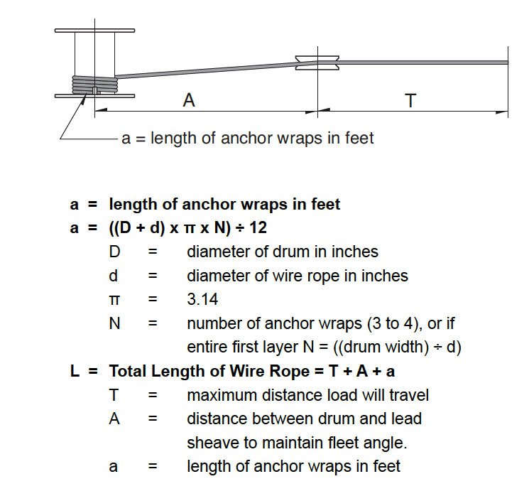
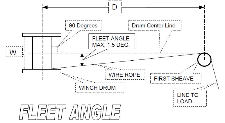
In order to insure proper wrapping on the drum and no undue wear of the wire rope, the fleet angle should be kept as small as practical. This is important to consider during the planning of a winch installation. Sheaves and drums should be placed so that the fleet angle will be equal on each side of the centerline of rope travel.
For a smooth drum a maximum fleet angle of 1-1/2 degrees is recommended. When the drum is grooved to suit the wire rope, the fleet angle should not exceed 2 degrees.
An importantpoint to consider is the selection of the proper type of core needed in the rope. Wire Ropes are made with either fiber core or steel wire core.
This center is usually composed of a separate 7×7 wire rope designated as IWRC. The steel core increases the strength by 7% and the weight by 10%. These steel cores provide more substantial support than fiber cores to the outer strands during the rope’s operating life. Steel centers resist crushing, are more resistant to heat and increase the strength of the rope.
The Design Factor being both the ratio between the minimum Breaking load of the rope and the rated capacity (RC) tells at what percentage of its ultimate strength a wire rope is operating. The Design Factor takes into consideration both normal rope wear and potential stresses in various applications. The best practice in determining an adequate design factor is to analyze the specific conditions involved inn each individual installation. The following example shows how to determine the Design Factor: If a rope is working under a max. operating load of 10,000 lbs. and is having an ultimate strength of 50,000 lbs., the factor is 5 which means it is operating at 20% of its ultimate strength.
The fleet angle is the angle formed between the rope running to or from the extreme left or right of the drum and a line drawn from the center of the sheave normal to the axis of the drum. For optimum efficiency, the angle here should not exceed 1 1/2 degrees for a smooth drum, or 2 degrees for a grooved drum. If the fleet angle is larger than the recommended limits, it can cause bad winding on smooth drums and rubbing against the flanges of the grooves. Too small a fleet angle should also be avoided since it will cause the rope to pile up against the flange head.
Proper alignment of sheaves is essential. The main sheave should line up with the center of the hoisting drum, otherwise both the rope and sheave flanges will be subjected to severe and rapid deterioration will occur. If rope speeds are high, sheaves should also be balanced.
Wire rope products will break if abused, misused or overused. Regular inspection and maintenance are necessary. Consult industry recommendation and OSHA standards before using.
PAHCO supplies specialised lifting equipment, such as high-performance steel wire ropes and first-class quality load hooks (up to 1,000t, certified according to DIN EN 10 204 / 3.1 B.) for the offshore industry.
PYTHON® stainless-steel wire rope is made in Germany in accordance to international standards, for example, Germanischer Lloyd (GL) DIN EN 10264/1-3 and DIN EN 10264-4, in addition to the American Petroleum Institute (API) Spec Q1® and Spec 9a for the oil and gas industry.
Favelle Favco Cranes have installed PYTHON Compac 35 non-rotating hoisting rope on top of the 2,073ft-high Shanghai Tower, the tallest building in Shanghai, China.
PYTHON high-performance wire rope provides substantial benefits over general purpose wire rope. Service life is dramatically increased and other applications gain from a significantly higher breaking load in order to reduce the size of the system components.
PYTHON Compac 35 is a HiPac-compacted, flexible rope with a very high breaking load, making it suitable for multi-layer spooling. Due to the complex LongLife core design, the rope is very flexible and durable, compared with rope having a low number of inner strands.
PYTHON Hoist C is a flexible, high-strength hoist rope for offshore cranes and deck cranes. The PlastGuard protection makes this rope less sensitive to high-fleet angles. The tight rope package provides very good pressure resistance on multi-layer drums. A long-lasting lubrication formula protects the rope during long idle times.
This rope is recommended for applications with high-dynamic, fatigue loads where the core might otherwise fail. The plastic core shield acts as a shock absorber.
PYTHON Super 8C is the classic upgrade rope for most crane types to increase rope service life performance while maintaining the ability to operate with fleet angles up to 4°.
The eight-strand construction provides an excellent combination of flexibility, fatigue life and abrasion-resistance. The rope can be supplied in dual-tensile strength where the outer strand wires are made from higher fatigue-resistant steel, which is available on request.
PYTHON wire rope range is ideal for a variety of lifting applications and equipment, including:Drilling lines for rigs: Solid 6R, Solid 6C and Super 6 C
The company aims to meet its clients’ requirements and expectations for high-performance, steel wire rope and load hooks, in addition to first-class crane and hoist equipment and accessories.
Ever since the development of wire rope, comprising multiple wire strands, spooling the wire has presented technical challenges. When wrapped in multiple layers, the upper layers have a tendency to crush the lower layers, while the lower layers have a tendency to pinch upper layers. The rubbing of rope against rope also has a tendency to cause wear.
These problems were addressed by Frank L. LeBus Sr., a supplier of drilling equipment to the oilfields of Texas, USA, who in 1938, patented the use of a groove bar on hoisting drums to guide the spooling of rope. Grooved shape steel segments were simply welded or screwed to existing plain steel drums.
The multilayer wire rope spooling system has undergone continuous refinement over the years and adapted for any application where long lengths of steel wire ropes must be wrapped in multiple layers quickly and smoothly. Examples include:
When the first layer has filled the drum, the second layer then travels back across the drum with each wrap of rope sitting precisely along the groove of two wraps of the first layer.
Cross winding is reduced to approximately 20% of the circumference of the drum, and 80% remains parallel to the flanges in the inner layer rope groove.
This parallel grooving evenly distributes the load between the individual layers and has been shown to increase substantially – by more than 500%, tests have shown – the life of the wire rope. The system has been used to mount ropes up.
In offshore applications, huge lengths of rope are often housed on drums. The anchor winches on Saipem"s Semac 1 pipe laying barge, for example, each hold 2,800 metres of 76mm (3 inch) diameter wire rope in 14 layers. Saipem"s Castorone, the world"s largest pipe laying vessel uses a wire rope that is 3,850m long and 152mm in diameter. It weighs 420t. The rope is pulled by capstan and stored on a massive Rema traction winches that feature the parallel grooving system, with an approximately back tension of 40t on the capstan.
Every system should be tailored to the application for which it is used. The groove pattern is engineered to suit the rope"s length, diameter and construction type.
In any multi-layer spooling application it is important that when the rope is first installed on the drum, it is done so under tension to avoid any slack on inner layers that can be crushed or nicked against the groove walls by outer layers.
The fleet angle is defined as the largest angle of the rope between the first sheave and the drum flange, relative to the centre line of the drum. With all type of drums, the rope is subject to a fleet angle which impacts on its behaviour and affects lifespan.
Fleet angle should be between 0.25° and 1.25°, depending on the rope construction. The fleet angle can be varied by moving the first sheave closer to or further away from the drum. If the sheave is too close to the drum, the fleet angle will be greater than 1.25°; if it is too far away, the fleet angle will be less than 0.25°.
Sometimes it is not possible to achieve the optimum fleet angle. Where there is no space to rig a sheave the requisite distance from the drum, two additional spooling devices are available. One is a fleet angle compensator, which is driven automatically by the rope tension. The other is a level winder that is mechanically driven. Both offer a solution to guide the cable along the drum between flanges, but each has its advantages and disadvantages.
The fleet angle compensator (FAC) is driven by the movement of the wire rope as it goes through the crossover sections of the drum. As the rope winds or unwinds, the FAC shaft automatically oscillates slowly, allowing its sheave to slide back and forth across the shaft to maintain an optimum fleet angle and guide the rope smoothly onto the drum.
Level winders can be hydraulically or electrically driven and computer controlled, or they can be simple mechanical devices. A mechanical level winder comprises a main shaft (the lead screw) with helical screw grooving along which the rope feeder travels. The rope feeder housing includes two vertical roller bars and one horizontal roller, or alternatively a wire rope sheave. The lateral movement of the housing is generated by a chain drive sprocket ratio between drum and lead screw, as shown in the image. The automatic level winder fitted is designed and engineered to be compatible with the grooving on the drum.
Oceanographic installations that spool rope up to 46 layers have demonstrated that level winders give synchronized and controlled spooling in the harshest, most testing conditions.


 8613371530291