
wire rope fleet angle made in china

It’s a good piece of information to have in your back pocket when you are adjusting or inspecting your rigging, or if you have the opportunity to buy a new rigging system. If you notice an excessive fleet angle, it could be a clue that something is wrong with your mounting or machinery.
In a properly installed manual lineset, the cable comes out as parallel to the groove of the block as possible. It can form an angle of 1.5 degrees into or out of the block, but no more—if the angle is greater, the cable will rub against the sheave. This can cause the cable to fray and eventually break, which can bring scenery or stage weights down on someone’s head.
Chances are you’ve seen the term zero fleet angle in articles or advertising for motorized rigging equipment. A hoist with zero fleet angle has a non-moving set of blocks above the drum. As the drum turns, it actually moves, so the cable piles on and off of the drum with no change in the angle between the drum and the cable.
Zero fleet angle hoists can be installed in greater density than other drum or line shaft hoists—allowing for more sets on stage. These hoists are particularly useful in renovations of historic theatres, where there may be minimal loft space.

PAHCO supplies specialised lifting equipment, such as high-performance steel wire ropes and first-class quality load hooks (up to 1,000t, certified according to DIN EN 10 204 / 3.1 B.) for the offshore industry.
PYTHON® stainless-steel wire rope is made in Germany in accordance to international standards, for example, Germanischer Lloyd (GL) DIN EN 10264/1-3 and DIN EN 10264-4, in addition to the American Petroleum Institute (API) Spec Q1® and Spec 9a for the oil and gas industry.
Favelle Favco Cranes have installed PYTHON Compac 35 non-rotating hoisting rope on top of the 2,073ft-high Shanghai Tower, the tallest building in Shanghai, China.
PYTHON high-performance wire rope provides substantial benefits over general purpose wire rope. Service life is dramatically increased and other applications gain from a significantly higher breaking load in order to reduce the size of the system components.
PYTHON Compac 35 is a HiPac-compacted, flexible rope with a very high breaking load, making it suitable for multi-layer spooling. Due to the complex LongLife core design, the rope is very flexible and durable, compared with rope having a low number of inner strands.
PYTHON Hoist C is a flexible, high-strength hoist rope for offshore cranes and deck cranes. The PlastGuard protection makes this rope less sensitive to high-fleet angles. The tight rope package provides very good pressure resistance on multi-layer drums. A long-lasting lubrication formula protects the rope during long idle times.
This rope is recommended for applications with high-dynamic, fatigue loads where the core might otherwise fail. The plastic core shield acts as a shock absorber.
PYTHON Super 8C is the classic upgrade rope for most crane types to increase rope service life performance while maintaining the ability to operate with fleet angles up to 4°.
The eight-strand construction provides an excellent combination of flexibility, fatigue life and abrasion-resistance. The rope can be supplied in dual-tensile strength where the outer strand wires are made from higher fatigue-resistant steel, which is available on request.
PYTHON wire rope range is ideal for a variety of lifting applications and equipment, including:Drilling lines for rigs: Solid 6R, Solid 6C and Super 6 C
The company aims to meet its clients’ requirements and expectations for high-performance, steel wire rope and load hooks, in addition to first-class crane and hoist equipment and accessories.

Wire rope is wound from high-strength metal strands for structural, mechanical actuation and motion control applications. Suppliers typically list the number of wires per strand followed by the number of strands per rope or cable. For example, products with a 7 x 19 designation have seven strands per cable and 19 wires per strand. Some wire rope products are enclosed in a metal wrap or jacket to provide additional surface protection and abrasion resistance. Examples include swaged aluminum casing (lockclad), armored cable, flat wrap, round wrap, wire wrap or braiding, and solid metal conduits or tubing. Other products are encased in a plastic jacket, coating or conduit, or feature a protective plastic filling that is infused into the finished cable. Wire rope assemblies, mechanical control cables, and wire rope slings with attached clips, eyes, handles or other fittings are also commonly available.
Physical specifications for wire rope include diameter, length, breaking strength, and core type. The size of the pulley, sheave or drum determines the maximum diameter of the rope or cable that can be fed through the transit or fitting. With control cables, diameter usually refers to the overall, conduit or outer casing dimension. With bare wire rope, the largest outer diameter (OD) is listed because the rope’s diameter is not uniform in size. Diameter and length are measured in inches (in). Breaking strength is the maximum tensile load or force in pounds (lbs) that a rope or cable will hold before breaking. It is multiplied by a safety factor to determine the actual operating or working load. There are several core types for wire rope. Plastic cores contain a solid, polyvinyl chloride (PVC) rod or a multi-filament rope made of polypropylene (PP), nylon or other synthetic material. Fiber core (FC) and hybrid products with metal and fiber strands are also available. Stranded metal wire core (SWC or SC) and independent wire rope core (IWRC) varieties are the strongest core types.
Wires are the basic components of wire rope. They are wrapped around a center wire to form strands. The strands are then wrapped around a core to form the rope. The core of the rope can be fiber, a wire strand, or a wire rope (IWRC - Independent Wire Rope Core). Wrapping just the wire strands together (without a core) creates a hollow core wire rope.
An important point to consider is the selection of the proper type of core needed in the rope. Wire ropes are made with either fiber core or steel wire core.
Strand Core (SC) - The strand core is usually confined to use in stationary ropes such as guys, suspension bridge cables, and in ropes of small diameter such as aircraft cable. It is also occasionally specified on installations where severe crushing may be experienced.
Fiber Core (FC) - This core is made of either prelubricated Java sisal fibers or plastic fibers, usually polypropylene. These fibers are made into an extremely hard laid rope which will stand up under the high pressures of rope service. These cores are used only when normal operating loads do not rupture the fibers. The polypropylene core is generally recommended when operating conditions other than crushing destroy the sisal. One example would be the presence of acid.
Independent Wire Rope Core (IWRC) - An independent wire rope center is usually specified to provide for one or more of three particular requirements, as follows:
An "IWRC" increases the strength by 7% and weight of a wire rope by 10%, and decreases the flexibility slightly. It greatly increases the resistance of the wire rope to crushing and is especially recommended on installations where severe loads are placed on ropes running over sheaves or wound on drums. Unless required for one or more of the above properties, the use of an "IWRC" should be avoided.
Wires are the basic building blocks of a wire rope. They lay around a "center" in a specified pattern in one or more layers to form a strand. The strands lay around a core to form a wire rope. Wire rope classifications and features the strands provide all the tensile strength of a fiber core rope and over 90% of the strength of a typical 6-strand wire rope with an independent wire rope core.
Characteristics like fatigue resistance and resistance to abrasion are directly affected by the design of strands. In most strands with two or more layers of wires, inner layers support outer layers in such a manner that all wires may slide and adjust freely when the rope bends.
As a general rule, a rope that has strands made up of a few large wires will be more abrasion resistant and less fatigue resistant than a rope of the same size made up of strands with many smaller wires. The basic strand constructions are illustrated as follow.
Single Layer Strand - The most common example of the single layer construction is a 7 wire strand. It has a single-wire center with six wires of the same diameter around it.
Seale Strand - This construction has two layers of wires around a center with the same number of wires in each layer. All wires in each layer are the same diameter. The strand is designed so that the large outer wires rest in the valleys between the smaller inner wires. Example: 19 Seale (1-9-9) strand.
Filler Wire Strand - This construction has two layers of uniform-size wire around a center with the inner layer having half the number of wires as the outer layer. Small filler wires, equal in number to the inner layer, are laid in valleys of the inner layer. Example: 25 Filler Wire (1-6-6f -12) strand.
Warrington Strand - This construction has two layers of wires around a center with one diameter of wire in the inner layer, and two diameters of wire alternating large and small in the outer layer. The larger outer layer wires rest in the valleys, and the smaller ones on the crowns, of the inner layer. Example: 19 Warrington [1-6-(6+6)].
The following common wire rope constructions are known as class constructions: 6 x 7, 6 x 19, 6 x 37, 7 x 19, and 8 x 19. Within a given class construction, the number of wires is allowed to vary within established industry guidelines. For example, a 6 x 37 class fiber core rope may have 27 to 49 wires in one strand.
When wires and strands are shaped into the form they will take on as a wire rope, the wire rope is called preformed. Preformed wire rope is easier to handle, resists kinking, and won"t unravel when cut. All of our wire rope is preformed (unless noted). Lubrication is provided on many ropes to increase service life.
Abrasion - Surface wear on the wires of a wire rope occurs as the wire rope moves over any surface. A wire rope constructed of strands with fewer wires will be more abrasion resistant than wire rope made with more wires. For example, 6 x 19 rope construction is more abrasion resistant than 6 x 37 construction.
Fatigue - Caused when a wire rope is repeatedly bent around drums and pulleys. A wire rope constructed of strands with more wires is more fatigue resistant than one made of strands with fewer wires. For example, 7 x 19 construction is more fatigue resistant than 7 x 7 construction.
Crushing - Any external force that causes a wire rope to become flattened or distorted and lead to breakage. This is especially true when a wire rope is used on drums and pulleys. In general, strand core and IWRC wire ropes are more crush resistant (less susceptible to flattening and distortion) than fiber and hollow core wire ropes.
Flexibility - A measure of the wire rope"s ability to stand up to bending stresses such as repeated movement over drums and pulleys. Typically, small diameter fiber core and hollow core wire ropes are more flexible than large diameter strand and IWRC wire ropes. For wire ropes of the same diameter, flexibility increases as the number of wires per strand increases. For example, a 1/4" diameter 7 x 19 construction wire rope is more flexible than a 1/4" diameter 7 x 7 construction wire rope.
Fleet angle is usually defined as the included angle between two lines, one which extends from a fixed sheave to the flange of a drum and the other which extends from the same fixed sheave to the drum in a line perpendicular to the axis of the drum.
If the drum incorporates helical grooving, the helix angle of the groove needs to be added or subtracted from the fleet angle as described above to determine the actual fleet angle experienced by the rope.
When spooling rope onto a drum it is generally recommended that the fleet angle is limited to between 0.5° and 2.5°. If the fleet angle is too small, i.e. less than 0.5°, the rope will tend to pile up at the drum flange and fail to return across the drum. In this situation, the problem may be alleviated by introducing a "kicker" device or by increasing the fleet angle through the introduction of a sheave or spooling mechanism.
If the rope is allowed to pile up it will eventually roll away from the flange creating a shock load in both the rope and the structure of the mechanism, an undesirable and unsafe operating condition.
Excessively high fleet angles will return the rope across the drum prematurely, creating gaps between wraps of rope close to the flanges as well as increasing the pressure on the rope at the cross-over positions.
Even where helical grooving is provided, large fleet angles will inevitably result in localised areas of mechanical damage as the wires "pluck" against each other. This is often referred to as "interference" but the amount can be reduced by selecting a Lang’s lay rope if the reeving allows. The "interference" effect can also be reduced by employing a dyform rope which offers a much smoother exterior surface than conventional rope constructions.
Where a fleet angle exists as the rope enters a sheave, it initially makes contact with the sheave flange. As the rope continues to pass through the sheave it moves down the flange until it sits in the bottom of the groove. In doing so, even when under tension, the rope will actually roll as well as slide. As a result of the rolling action the rope is twisted, i.e. turn is induced into or out of the rope, either shortening or lengthening the lay length of the outer layer of strands.
As the fleet angle increases so does the amount of twist. To reduce the amount of twist to an acceptable level the fleet angle should be limited to 2.5° for grooved drums and 1.5° for plain drums and when using rotation-resistant low rotation and parallel-closed ropes the fleet angle should be limited to 1.5°.
However, for some applications it is recognised that for practical reasons it is not always possible to comply with these general recommendations, in which case the rope life could be affected.

The constant endeavor for improvement & technological upgradation By our principal has resulted in perpetual development of innovative & user friendly wire rope products. These wire ropes are best suited for the oil drilling industries their applications and are available in various construction with sizes staring from 6mm onwards and are available in ex-stock. Steel core ropes are made with IWRC as cores and not strands. We have devises of superior quality practices in our company too and make sure that each and every product we manufacture bears the stamp of excellence.
An important point to consider is the selection of the proper type of core needed in the rope. Wire Ropes are made with either fiber core or steel wire core.
This center is usually composed of a separate 7×7 wire rope designated as IWRC. The steel core increases the strength by 7% and the weight by 10%. These steel cores provide more substantial support than fiber cores to the outer strands during the rope"s operating life. Steel centers resist crushing, are more resistant to heat and increase the strength of the rope.
The Design Factor being both the ratio between the minimum Breaking load of the rope and the rated capacity (RC) tells at what percentage of its ultimate strength a wire rope is operating. The Design Factor takes into consideration both normal rope wear and potential stresses in various applications. The best practice in determining an adequate design factor is to analyze the specific conditions involved inn each individual installation. The following example shows how to determine the Design Factor: If a rope is working under a max. operating load of 10,000lbs. and is having an ultimate strength of 50,000lbs., the factor is 5 which means it is operating at 20% of its ultimate strength.
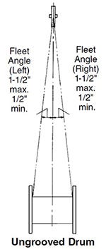
The fleet angle is the angle formed between the rope running to or from the extreme left or right of the drum and a line drawn from the center of the sheave normal to the axis of the drum. For optimum efficiency, the angle here should not exceed 1 1/2 degrees for a smooth drum, or 2 degrees for a grooved drum. If the fleet angle is larger than the recommended limits, it can cause bad winding on smooth drums and rubbing against the flanges of the grooves. Too small a fleet angle should also be avoided since it will cause the rope to pile up against the flange head.
Proper alignment of sheaves is essential. The main sheave should line up with the center of the hoisting drum, otherwise both the rope and sheave flanges will be subjected to severe and rapid deterioration will occur. If rope speeds are high, sheaves should also be balanced.
Wire rope products will break if abused, misused or overused. Regular inspection and maintenance are necessary. Consult industry recommendation and OSHA standards before using.
Using a winch to lift or position a load gives your project flexibility because you can have this material handling muscle positioned in various ways. You can place the winch above the load and use it vertically as a hoist, or have it on the same level of the load to pull horizontally, or use pulleys with it so you can position the winch where you want it and move the load in the direction(s) that you need it to go. But when you are determining where to position your industrial winch, it is important that you consider the critical distance needed to maintain the necessary fleet angle to keep things safer and in proper working order.
What is fleet angle? Fleet angle is the angle between the wire rope and an imaginary line extending perpendicular to the drum. This angle varies with the width of the drum and the distance between the lead sheave and the drum. The proper fleet angle helps the wire rope to wind evenly onto the drum, and helps to reduce wear to the wire rope, drum, and lead sheave. Too large a fleet angle will cause the wire rope to wind loosely, overlap and possibly jump the flange and cause severe damage to the equipment. That"s why it"s important to properly distance the winch from the lead sheave (also sometimes called fixed sheave) when you are determining where to position your winch. A maximum fleet angle of 1-1/2° for smooth drums, and 2° for grooved drums, helps the wire rope wind uniformly. A narrower drum can also help stay within the recommended fleet angle if the critical fleet angle distance can’t be improved. Diagrams below are examples of common rigging layouts that show where critical fleet angle distances are to be measured so you can stay within the proper maximum fleet angle.
So next time you want to take advantage of the benefits of using an industrial winch to move or position a load, make sure you are practicing proper distancing...fleet angle distancing.

The present application relates to a sheave for use in handling lines, ropes, cables, or other flexible elongate tensile elements. More particularly, the present application relates to a sheave that can be used in a relatively more flexible manner when handling such lines, ropes, or cables. Still more particularly, the present application relates to a sheave for use with a block and tackle arrangement that accommodates conditions when the travelling block is positioned out from below or out of alignment with the crown block, which creates a fleet angle between the handling line and the plane of the sheave. BACKGROUND OF THE INVENTION
Lifting assemblies such as those found on cranes and other material handling systems may include a crown block and a travelling block. Generally, the crown block is stationary relative to the supporting structure, which could be a crane boom, derrick, a bridge, a trolley, or some other aspect of the material handling system. In contrast, the travelling block may be movable generally upward and downward relative to the crown block by paying out or hauling in cable or rope. Each of the crown block and travelling block may include one or more sheaves and wire rope may be reeved around the sheaves between the crown block and the travelling block to create a block and tackle arrangement. The sheaves in the blocks may have grooves in them for controlling the position of the wire rope as it engages the sheave.
In the context of a drill rig, such as an oil drill rig, the crown block may be supported by a derrick and the traveling block may be suspended below the crown block and used for lifting and/or supporting tubulars in the well bore. A winch or drawworks may be connected to one end of the wire rope and may be used to raise and lower the travelling block. In some operations, such as when new sections of pipe are being lifted into place for example, the travelling block may be pulled horizontally and out from directly below the crown block. This may create a fleet angle between the wire rope and the plane of the sheave on either or both of the travelling and crown blocks. As may be appreciated, this fleet angle may cause the wire rope to hang up on the rim or lip of the sheave as it enters the sheave such that the wire rope intermittently slips into the groove rather than continuously feeding into the groove. This hang up and slippage can cause wear on the sheave and/or the rope leading to premature failure and replacement costs. BRIEF SUMMARY OF THE INVENTION
In some embodiments, a sheave may include a body portion with a circular circumference and defining a center plane. The sheave may include a bore extending through the body portion and the bore may be configured for receiving a shaft and may also be configured to allow the body portion to rotate in the center plane. The sheave may also include a rope groove arranged on the circular circumference. The rope groove may include a radiused bottom with a first end and a second end. The rope groove may also include a pair of opposing sidewalls each extending directly and tangentially from one of the first and second end and the sidewalls may have a curved profile.
In another embodiment, a block for use in a block and tackle arrangement may be provided. The block may include a body portion and a sheave may be arranged in the body portion for substantially free rotation. The sheave may define a center plane and may have a groove arranged along a circumference thereof. The groove may include a radiused bottom with a first end and a second end. The rope groove may also include a pair of opposing sidewalls each extending directly and tangentially from one of the first and second end and having a curved profile.
The present disclosure, in some embodiments, relates to material handling systems employing crown blocks and/or travelling blocks that include fleet angle tolerant sheaves. The crown and travelling blocks may be part of a block and tackle arrangement where the crown and travelling blocks are connected to one another with one or more returning sections of wire rope. That is, wire rope may extend from a winch or draw works to the crown block, down to the travelling block, and back up to the crown block. As the wire rope passes through each block, it may be reeved around a separate sheave for each pass through the block. The sheaves in the blocks may have a uniquely shaped sheave groove. The sheave groove may be shaped to accommodate relatively high and/or frequent fleet angles that may otherwise cause the wire rope to hang up on the rim of the sheave and intermittently drop into the groove. Without this disclosed groove, this hanging up and slipping may often be heard by crews as the travelling block travels and the wire rope slips. That is, as the rope slips and the sheave drops slightly and reengages the rope with the bottom of the groove, the impact can and resulting tightening of the rope can be heard. This undesired rubbing and/or wear on the rim and sidewalls of the groove which can lead to premature failure or replacement of the sheaves and/or the wire rope.
In the oil industry, there are regulations and restrictions on the shape and profile of sheaves such as specified in American Petroleum Institute (API) 8A and 8C. The presently disclosed profile, in some embodiments, creates a sheave that can accommodate higher fleet angles while remaining in compliance with API 8A and 8C.
As shown in FIG. 1, a simplified system 100 of a block and tackle arrangement in conjunction with a draw works 102 is shown. As shown, a portion of wire rope or other lifting line 104 may extend from the draw works 102 to the crown block 106. The crown block 106 may be supported by a derrick 108 or other supporting structure. The lifting line 104 may pass through the crown block 106 and extend down to the travelling block 110. In a single line set up, the lifting line 104 may be dead-ended at the travelling block 110. In other embodiments, as shown, the lifting line 104 may be reeved through the travelling block 110 across a sheave 112 and may return to the crown block 106. Each time the lifting line passes through the travelling block 110 or the crown block 106, the lifting line 104 may pass across a sheave 112 for guiding the line 104 through the block and allowing the line 104 to translate through the block as the travelling block 110 is lifted and/or lowered by hauling in or paying out, respectively, the lifting line 104. Depending on the number of returns from the travelling block 110, differing reeving patterns may be used. In the present embodiment, 12 lines are used including 6 lines extending downward from the crown block to the travelling block and 6 lines returning to the crown block. In other embodiments, 14 or 16 lines may be used or another number of lines may be used depending on the desired capacity of the system. In some embodiments, the crown block may be skewed slightly or the sheaves in the crown block may be skewed to accommodate the lateral translation of each line as it returns from the travelling block to the crown block and engages a sheave adjacent to the sheave that it previously passed across.
As shown in FIG. 1, in some circumstances, the travelling block 110 may be pulled out from below the crown block 106. For example, in some cases, the travelling block 110 may be lifted or lowered adjacent to tubulars in line with the well center to put the travelling block in position for the next anticipated operation. As the travelling block 110 is pulled out from below the crown block 106, as shown, the lifting lines 104 may become angled (i.e., fleet angle) as they exit the travelling block 110 causing the lifting line 104 to engage the outer lips of the grooves on the sheaves 112 in the block 110, causing the line 104 to ride along the lips of the grooves and intermittently drop into the groove. In some cases, both the travelling block 110 and the crown block 106 may experience wear due to the increased fleet angle, while in other embodiments, one or the other may experience the wear.
Referring now to FIG. 2, a sheave 112 of one of the crown and/or travelling block 106, 110 of FIG. 1 is shown. The sheave 112 may include a body portion or web 114, an axle engaging portion or hub 116, and a rope engaging portion or rim 118. As mentioned, the sheave 112 may be configured to guide a rope 104 passing through a crown or travelling block 106, 110. The sheave 112 may be particularly adapted to maintain the rope 104 in a substantially constant tension condition as it passes through the block and may also be adapted to reduce or minimize kinking or abrupt bends in the rope 104, which can lead to high stress concentrations and may create areas of fatigue or wear on the rope 104.
The body portion or web 114 of the sheave 112 may include a substantially robust structure configured for transferring tensile loads from the wire rope 104 to and through the axle engaging portion 116 of the sheave 112 to an axle or supporting structure of the sheave 112. Where the rope engaging portion 118 of the sheave 112 is substantially circular, the tensile load in the wire rope 104 may impart a substantially uniform and radially acting pressure along the rope engaging portion 118 of the sheave 112. Depending on the rigidity of the rope engaging portion 118 relative to the rigidity of the body portion 114, the body portion 114 may transfer the substantially uniform and radially acting pressure substantially directly inward to the axle. In other embodiments, where the body portion 114 is more akin to a spoke arrangement (either because it is relatively thin or because of an actual spoke-like structure), the rigidity of the rope engaging portion 118 may function more akin to a compressed hoop. In this embodiment, the deflection of the hoop under the load of the line 104 may create tension in the body portion 114 on the side of the body portion 114 opposite the load, thereby causing the body portion 114 to transfer the load to the axle engaging portion 116.
In some embodiments, the body portion 114 may be a substantially planar structure that is substantially circular such that the rope engaging portion 118 may be arranged substantially adjacent to the body portion 114 and immediately radially outward from the body portion 114. The body portion 114 may be substantially plate-like having a substantially constant thickness. In other embodiments, the thickness of the body portion 114 may be thicker near the center of the sheave 112 and around the axle engaging portion 116, for example. The body portion 114 may have one or more ribs arranged on its surface extending substantially radially outward from the center of the body portion 114 to the outer periphery of the body portion 114.
The rope engaging portion or rim 118 of the sheave 112 may be arranged along an outer periphery of the body portion 114 opposite the axle engaging portion 116. The rope engaging portion 118 may be adapted to cause the lifting line or rope 104 to conform to a selected shape (i.e., a radial arc shape) as it passes around the perimeter of the sheave 112. As such, and as shown in FIG. 2, the rope engaging portion 118 may include a generally circular shape when viewing the sheave 112 from the side. The diameter of the sheave 112 and, thus, the diameter of the rope engaging portion 118 may depend on several factors including the rope diameter, the design load, the block size, and several other factors. In some embodiments, the diameter of the rope engaging portion 118 (measured at outside or maximum diameter) may range from approximately 20 inches to approximately 114 inches or from approximately 40 inches to approximately 100 inches or from approximately 60 inches to approximately 80 inches.
The rope engaging portion 118 may also be configured to cause the rope 104 to remain in alignment with a center plane 122 of the sheave 112 as it passes around the sheave 112. This may be particularly useful as the fleet angle 124 increases where sidewalls of the rope engaging portion 118 hold the rope generally centered on the sheave 112 as it passes around the sheave 112. As shown in FIG. 3, when viewed in cross-section, the rope engaging portion 118 may include a generally saddle or groove shape, for example. The rope engaging portion 118 may be defined by a base portion 126 extending around the periphery of the body portion 114. The base portion 126 may be thickened region around the periphery of the body portion 114 of the sheave 112 or the base portion 126 may have a thickness similar or the same as the body portion 114. In the latter case, the base portion 126 of the rope engaging portion 118 may be an outer annular portion of the body portion 114, for example. In the embodiment shown in FIG. 2, the base portion 126 is consistent with the former case where the base portion 126 includes a thickened region along the periphery of the body portion 114. The thickened region may have a radial height 128 sufficient to accommodate a groove which may be sized and shaped to accommodate a selected rope diameter or range of diameters. For example, in some embodiments, the radial height 128 of the base portion 126 may range from approximately 2⅜ inches to approximately 5 inches. The thickened region may have a width 130 when viewed in cross-section for accommodating the rope diameter and providing sidewalls along the sides of the rope. For example, in some embodiments, the width 130 may range from approximately 2⅜ inches to approximately 4½ inches.
Turning now to FIG. 4, a close-up view of a cross-section of the rope engaging portion is shown. As shown, the base portion 126 may include a groove 132 that is particularly configured to receive a circular diameter rope and may provide a seat for the rope as it lays on the outer peripheral surface of the sheave 112. In particular, the groove 132 may be defined by a bottom surface 134 and a pair of opposing sidewalls 136 each extending upwardly from the bottom surface 134 to respective lips 138.
The bottom surface 134 of the groove 132 may be adapted to nestably engage the lifting line or wire rope 104 as it presses against the sheave 112. The bottom surface 134 may thus be a concave surface extending between a pair of upper ends 140. The concave surface may have a curvature particularly adapted and modeled after the shape of the cross-section of the wire rope 104. In particular, the bottom surface 134 may have a curvature matching the curvature of the outer surface of the wire rope 104 or the curvature of the bottom surface 134 may be based on a radius slightly larger than the radius of the wire rope 104. For example, where the bottom surface curvature is too tight, the rope 104 may not fully engage the bottom surface 134 and may, instead, be hung up on the sidewalls 136 of the groove 132 causing excessive wear on the sidewalls 136 and pinching of the rope 104, which may cause the rope 104 to deteriorate. Where the bottom surface curvature is too broad, the rope 104 may have a tendency to flatten as it passes across the sheave 112, which may also cause the rope 104 to deteriorate more quickly. As such, the bottom surface curvature may be similar to the curvature of the outer surface of the wire rope 104. In some embodiments, the curvature may be defined by a radius that is based on the rope diameter multiplied by a factor ranging from approximately 1.01 to 1.2. In some embodiments, where the sheave groove is designed to meet API specifications, the factor may range from 1.06 to 1.1.
The bottom surface 134 may define an included angle 142 defining how much of the bottom surface 134 comes into contact with the surface of the wire rope. In some embodiments, the bottom surface 134 may have an included angle 142 ranging from approximately 0 degrees to approximately 60 degrees or from approximately 20 degrees to approximately 40 degrees or the included angle 142 may be approximately 30 degrees. In some embodiments, where sheaves 112 are designed to meet specification of the American Petroleum Institute (API) (e.g., API 8A and 8C), the included angle 142 may be approximately 30 degrees or the angle 144 subtended by the upper ends 140 may be approximately 150 degrees. Still other included angles 142 may be provided depending on the shape, size, and type of rope or lifting line being provided. In any of the above cases, the angle 146, relative to the horizontal of the upper end 140 of the bottom surface 134 may be approximately ½ of 180 degrees less the included angle 142. That is, where the included angle is 30 degrees, for example, the upper ends 140 of the bottom surface 134 may extend upwardly at an angle of approximately 75 degrees from the horizontal. In addition, as shown, the bottom surface of the groove may be symmetrical about the centerline of the sheave and, as such, the included angle 142 may be made up of two half angles 143 as shown.
The sidewalls 136 of the groove 132 may be adjacent and/or immediately adjacent to the upper ends 140 of the bottom surface 134 and may extend upwardly from the upper ends 140 of the bottom surface 134. As shown, the sidewalls 136 may initially be tangential to or in alignment with the upper ends 140 of the bottom surface 134 such that, initially, the sidewalls 136 extend upwardly from the horizontal at the same angle as the upper ends 140 of the bottom surface 134. In other embodiments, the sidewalls 136 might not be tangential and may, instead, extend at a shallower or more upright angle relative to the upper ends 140 of the bottom surface 134. Where sheaves are designed to meet API specifications, the sidewalls 136 may initially extend from the upper ends 140 of the bottom surface tangentially as shown.
As shown in FIG. 4, the sidewalls 136 may be curved or contoured sidewalls. That is, in contrast to groove profiles where the sidewalls are flat and extend tangentially upwardly from the bottom surface 134, the sidewalls 136 of FIG. 4 are not flat and, instead have a curved surface. As shown, while the sidewalls 136 may initially be tangential to the upper ends 140 of the bottom surface 134, the sidewalls 136 may have a curvature that may be defined by a radius 147. The curvature may be a generally convex curvature relative to the groove space 132 and, as such, may cause the sidewalls 136 to increasingly diverge away from the groove space 132 as the sidewalls 136 extend upwardly. That is, while flat sidewalls may be said to diverge as they extend upwardly, the present sidewalls increasingly diverge due to the curvature. The radius line of the curved sidewall 136 may extend substantially perpendicularly to the tangent point at the upper ends 140 of the bottom surface 134 and may have a center point 148 defined by the length of the radius 147. That is, for an included angle 142 of approximately 30 degrees and a sidewall curvature radius of R inches, the center point 148 of the radiused sidewall 136 may be R inches down and to the right of the upper end of the right upper sidewall at an angle of approximately 15 degrees. While a radiused curve has been described, in other embodiments, the curvature may be other parabolic curves, elliptical curves, or spiral shapes, for example. The amount of curvature of the sidewalls 136 may depend on a variety of factors including the rope diameter, the sheave diameter, and the desired fleet angle to be accommodated.
In some embodiments, depending on the rope diameter, the sheave diameter, and the desired fleet angle, the radius of the sidewalls may range from approximately 3 inches to approximately 30 inches or from approximately 4 inches to approximately 25 inches or from approximately 5 inches to approximately 21 inches. Any particular value within ranges mentioned may have particular advantages and may be selected. Still other radii outside or within the ranges described may be provided. In one example model, for a design fleet angle of 7 degrees, the following wall radii were determined:
Wall Radius “R wall” (inches) Rope Sheave Diameter Dia. 72 78 1.750 13.00 11.75 1.875 14.50 13.00 2.000 17.50 15.50 2.125 21.00 18.75 2.250 23.25 20.50
In addition, for a sheave diameter of 60 inches, for example, a wall radius ranging from 5⅝ inches to approximately 16 inches may be used. For example, with a sheave diameter of 60 inches and a rope diameter of 1⅛ inches, a wall radius of 5⅝ inches may provide for a fleet angle of 7 degrees.
It is to be appreciated that the wall radius may increase the width of the groove at the outer peripheral edge of the sheave. This increased groove width may accommodate the fleet angle by limiting the engagement of the rope with the lip of the sheave groove, which may reduce or prevent the rope from hanging up on the sheave groove and intermittently slipping into the groove. As such a smoother operation may be performed and sheave and rope life may be increased.
The upper lips 138 on each side of the groove 132 may be tangential to an upper end 150 of the sidewall. In other embodiments, the upper lips 138 may extend at angle different than the upper end angle of the sidewalls 136. The upper lips 138 may include a curved surface having a curvature greater than that of the sidewall 136 and may have a flat top surface defining the outermost peripheral surface of the sheave 112. In some embodiments, this outermost peripheral surface may not be flat but, instead, may be curved as the lip 138 may curve away from the sidewall 136 and continue to an outside surface of the base portion 126 of the rope engaging portion 118 of the sheave 112. The curved surface portion of the lip 138 may have a radius ranging from approximately ⅛ inch to approximately ½ inch or from approximately 3/16 inch to approximately ⅜ inch or the curved surface portion of the lip may have a radius of approximately ¼″. Still other radii outside or within the ranges mentioned may be provided.

Multi-layer drum systems should use strand- or swage compacted Python® rope constructions having a steel core. The higher fill factor of such rope constructions will offer a greater resistance to crushing and flattening than conventional rope types. This is particularly important for boom hoist ropes on lattice boom cranes at the cross over point from one rope winding to the next.
Cranes equipped with multi-layer drum systems which require rotation-resistant or non-rotating rope are best served with Python Compac® 18 and Python Compac® 35. To further reduce drum crushing have the rope layers wound onto the drum with about 5-10% of the WLL and avoid that the first layer unspools and re-spools without tension. This would cause a ‘soft’ bottom layer which will flatten rather quickly.

LeBus International, in its continuing efforts to improve its spooling products, have followed the LeBus grooving pattern with a device that can compensate for the excessive fleet angles found on many drums. This device is called the Fleet Angle Compensator. It is a floating sheave on an eccentric shaft that redirects the line as it spools onto the drum. LeBus can also engineer diamond screw to match the customer’s drum. This can be integrated into a levelwind to form a positive levelwinding process on the drum.
LEBUS is a globally operating company with factories and agencies in the USA, Brazil, China, Germany, the UK and Singapore. At all locations, we are led by the spirit of customer service, ready to offer wire rope spooling solutions anywhere in the world.


 8613371530291