
wire rope flexibility chart free sample

Wire rope is also known by many other names, such as: wire, multi-strand wire, flexible wire, cable, cord, steelcord, etc. but it is essentially a collection of small filaments wound around each other in a manner that largely retains its shape when bent, crushed and/or tensioned.
It is a system for significantly increasing the strength and flexibility of steel wire and is used in almost every important application we see around us. For example: suspension bridges, tyres, brake and accelerator cables (in cars), high-pressure flexible pipes, lifting and rigging cables, electrical conductors, etc. and it comes in many different forms. Fig 2 shows just a very small sample of available designs.
With minor variations, the generally accepted method for designating a wire rope construction in the industry is by describing it numerically. For example:
Whilst "IWRC" wire ropes offer a slightly greater tensile capacity (≈7%) than those with fabric or polymer fillers, the additional strength does not come from the tensile capacity of the core filaments but from improved dimensional stability under load. And whilst they are also much more resistant to crushing, they are stiffer than fibre core ropes and therefore not recommended for applications where tension occurs under bending.
Warrington (Fig 1) is a parallel lay construction with an outer layer comprising wires of alternating large and small diameters, each outer layer having twice the number of wires as the layer immediately beneath. The benefit of this design is to increase packing and therefore strength density, however, unless the different diameter filaments are of the same strength (unlikely), this construction is limited by the strength of the weakest filaments.
Seale (Figs 1 & 2 6x36) is also a parallel lay construction but with the same number of wires in each wire layer. All the wires in any layer are the same diameter. This is an alternative to the Warrington construction, with similar benefits and disadvantages.
Regular lay constructions are used much more widely (than Lang lay) because they have excellent structural stability and less tendency to unwrap under tension (see Rotating vs Non-Rotating below). However, because it has a knobbly (undulating) surface it will wear both itself and any surface over which it is run much more quickly than Lang lay wire rope.
Lang lay constructions have a flatter surface than regular lay constructions giving them better resistance to wear and bending fatigue, especially when made from flattened (elliptical) filaments. They are, however, much less structurally stable and subject to birdcaging if the wire rope is over-bent or twisted against its wrapped direction.
"Regular Lay", multi-strand constructions are normally subject to slightly less rotation under tension (than Lang lay) due to the opposite helical direction of the filaments (within the strands) and the strands (within the rope), however, you can improve their rotation characteristics still further by;
Fillers (Fig 2) may be fabric, polymer or even smaller diameter filaments (e.g. 6x36). Whilst they contribute little to the tensile strength of wire rope, they can significantly; improve performance under bending (fabric and polymer cores only), reduce axial growth, reduce rotation in rotation-resistant constructions, improve structural stability and increase fatigue life.
This filler material should not be included in strength (tensile capacity) calculations, but must be included in those for axial stiffness (extension). If it is ignored, your calculations will reveal excessive extension as the wire rope collapses.
Suspension bridges tend to be constructed from densely packed, single strand plain "Wire Rope" constructions using large diameter galvanised filaments. Little heed is paid to rotational resistance as strength is paramount and once tensioned, they should remain in that loading condition for their design life.
Lifting & winching normally require wire ropes of good flexibility and fatigue resistance. Therefore they tend to be similar to 6x36 but with fibre core instead of the IWRC in Fig 2
Hosecord is suitable for HPHT flexible pipes as lateral flexibility is generally considered less important than minimal longitudinal growth or maximum tensile strength (per unit cross-sectional area).
Remote operating cables such as hand-brakes and accelerators on cars normally only work in tension so they need to be strong but not necessarily stiff (as they are fully contained in reinforced outer sheaths). These tend to be manufactured from large diameter "TyreCord" or small diameter single-strand "Wire Rope".
Wire rope does not obey Hooke"s law. Therefore, you cannot accurately predict how much it will stretch for any specified force. This unpredictability applies to any section removed from the same manufactured length of cord and even between cords produced to the same specification but by different manufacturers.
CalQlata has decided that the accuracy of axial stiffness (EA) of wire rope falls outside its own levels of acceptability and therefore does not include it in the wire rope calculator. The extension calculated in the Wire Rope calculator (δLᵀ) is based upon the effect of axial tension on packing density. It is therefore important that core material is not ignored when using the calculator to evaluate this characteristic.
Wire rope does not obey Hooke"s law. Therefore, you cannot accurately predict how much it will twist for any specified torque. This unpredictability applies to any section removed from the same manufactured length of cord and even between cords produced to the same specification but by different manufacturers.
CalQlata has decided that the accuracy of torsional stiffness (GJ) of wire rope falls outside its own levels of acceptability and therefore does not include it in the wire rope calculator.
1) No wire rope calculator, whether dedicated or generic, will accurately predict the properties of any single construction under a wide range of loading conditions
2) No wire rope calculator, whether dedicated or generic, will accurately predict any single property for a range of constructions under a wide range of loading conditions
The only wire rope that can be reliably analysed is that which is used for suspension bridges, because; it comprises a single strand, is very densely packed, has negligible twist, contains filaments of only one diameter, is never subjected to minimum bending and every filament is individually tensioned.
There is a very good reason why manufacturers do not present calculated performance data for construction or design proposals, because even they cannot accurately predict such properties and quite rightly rely on, and publish, test data.
During his time working in the industry, the wire rope calculator"s creator has seen, created and abandoned numerous mathematical models both simple and complex. He has gradually developed his own simplified calculation principle based upon his own experience that still provides him with consistently reliable results of reasonable accuracy.
The purpose of CalQlata"s wire rope calculator is to provide its user with the ability to obtain a reasonable approximation for a generic construction, after which, accurate test data should be sought from the manufacturer for the user"s preferred construction.
The calculation principle in the wire rope calculator is based upon changes in the properties of the wire rope that occur with variations in packing density under tension
Bearing in mind the above limitations CalQlata can provide the following assistance when generating (manipulating) the wire rope calculator"s input data and interpreting its output
Alternatively, for wire rope with multiple filament diameters, you need to find an equivalent diameter with the following proviso; you must enter the minimum filament yield stress (SMYS)
It is expected that apart from fillers, all the material in the wire rope will be identical and therefore have the same density, i.e. using different materials will result in less than "best" performance. However, if such a construction is proposed, you can calculate an equivalent density as follows:
It is expected that apart from fillers, all the material in the wire rope will be identical and therefore have the same tensile modulus, i.e. using different materials will result in less than "best" performance. However, if such a construction is proposed, you should enter the highest tensile modulus.
The wire rope calculator simply adds together the total area of all the filaments and multiplies them by the SMYS entered, which represents a theoretical maximum breaking load that would exist if this load is equally shared across all of the filaments and the lay angles have been arranged to eliminate localised (point) loads between adjacent filaments.
If the wire rope has been properly constructed it is likely that its actual break load will be greater than 80% of this theoretical value. However, given the vagaries of wire rope construction, the actual break load can vary considerably dependent upon a number of factors. CalQlata suggest that the following factors may be used to define the anticipated break load of any given construction:
The axial stiffness and strain under load will be affected by this value, hence the reason why the most reliable (predictable) constructions tend to be minimum [number of] strands and single filament diameter. The Warrington and Seale constructions and combinations thereof tend to provide the highest packing density (but lowest flexibility) and there is little to be gained from using these constructions in more than single stranded wire rope as the benefit of high-packing density will be lost with no gain in flexibility.
The anticipated second moment of area of the wire rope at tension "T" due to deformation but insignificant flattening as it is assumed the wire rope will be bent over a formed (shaped) sheave or roller.
The anticipated tensile modulus of the wire rope at tension "T" due to deformation but insignificant flattening as it is assumed the wire rope will be bent over a formed (shaped) sheave or roller.
It is not advisable to induce this bend radius in operation due to uncertainties associated with wire rope construction, especially for dynamic applications. CalQlata suggests that a similar approach to that used for the break load (Fb) above also be applied here, i.e.:
A change in diameter will occur in all wire rope, irrespective of construction, until packing density has reached a limiting value. The value provided in the wire rope calculator is that which would be expected if the construction remains intact at the applied tension "T"
Unreliability of this value increases with complexity in wire rope due to its longitudinal variability and the increased likelihood of premature failure.
The accuracy of this data will range from about ±1% for wire rope with a single strand and a single filament diameter, up to about ±15% for constructions of similar complexity to OTR cord
A change in length of any wire rope will occur due to the fact that the packing density increases with tension. This is not, however, a linear relationship.
This can be an unreliable value as illustrated by tests carried out (by the author) on two pieces of wire rope supplied by the same well-known manufacturer both of which were cut from the same length, varied in tensile capacity by only 1.5%, but the tensile modulus (and strain at break) varied by 34%. Whilst this was an extreme case, significant variations have been seen in wire rope manufactured by a number of manufacturers.
Whilst the wire rope calculator does not calculate axial stiffness (see Calculation Limitations 9) above), CalQlata can suggest the following rule-of-thumb that will provide reasonable results for most constructions at the applied tension "T":
Whilst the wire rope calculator does not calculate bending stiffness (see Calculation Limitations 8) above), CalQlata can suggest the following rule-of-thumb that will provide reasonable results for most constructions at the applied tension "T":
Low complexity means single strand and single wire diameter. Medium complexity means multi-strand and single wire diameter. High complexity means multi-strand and multiple wire diameters.
Wire rope and cable are each considered a “machine”. The configuration and method of manufacture combined with the proper selection of material when designed for a specific purpose enables a wire rope or cable to transmit forces, motion and energy in some predetermined manner and to some desired end.
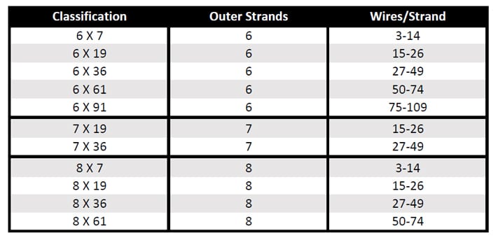
Two or more wires concentrically laid around a center wire is called a strand. It may consist of one or more layers. Typically, the number of wires in a strand is 7, 19 or 37. A group of strands laid around a core would be called a cable or wire rope. In terms of product designation, 7 strands with 19 wires in each strand would be a 7×19 cable: 7 strands with 7 wires in each strand would be a 7×7 cable.
Materials Different applications for wire rope present varying demands for strength, abrasion and corrosion resistance. In order to meet these requirements, wire rope is produced in a number of different materials.
Stainless Steel This is used where corrosion is a prime factor and the cost increase warrants its use. The 18% chromium, 8% nickel alloy known as type 302 is the most common grade accepted due to both corrosion resistance and high strength. Other types frequently used in wire rope are 304, 305, 316 and 321, each having its specific advantage over the other. Type 305 is used where non-magnetic properties are required, however, there is a slight loss of strength.
Galvanized Carbon Steel This is used where strength is a prime factor and corrosion resistance is not great enough to require the use of stainless steel. The lower cost is usually a consideration in the selection of galvanized carbon steel. Wires used in these wire ropes are individually coated with a layer of zinc which offers a good measure of protection from corrosive elements.
Cable Construction The greater the number of wires in a strand or cable of a given diameter, the more flexibility it has. A 1×7 or a 1×19 strand, having 7 and 19 wires respectively, is used principally as a fixed member, as a straight linkage, or where flexing is minimal.
Cables designed with 3×7, 7×7 and 7×19 construction provide for increasing degrees of flexibility but decreased abrasion resistance. These designs would be incorporated where continuous flexing is a requirement.
Selecting Wire Rope When selecting a wire rope to give the best service, there are four requirements which should be given consideration. A proper choice is made by correctly estimating the relative importance of these requirements and selecting a rope which has the qualities best suited to withstand the effects of continued use. The rope should possess:Strength sufficient to take care of the maximum load that may be applied, with a proper safety factor.
Strength Wire rope in service is subjected to several kinds of stresses. The stresses most frequently encountered are direct tension, stress due to acceleration, stress due to sudden or shock loads, stress due to bending, and stress resulting from several forces acting at one time. For the most part, these stresses can be converted into terms of simple tension, and a rope of approximately the correct strength can be chosen. As the strength of a wire rope is determined by its, size, grade and construction, these three factors should be considered.
Safety Factors The safety factor is the ratio of the strength of the rope to the working load. A wire rope with a strength of 10,000 pounds and a total working load of 2,000 pounds would be operating with a safety factor of five.
It is not possible to set safety factors for the various types of wire rope using equipment, as this factor can vary with conditions on individual units of equipment.
The proper safety factor depends not only on the loads applied, but also on the speed of operation, shock load applied, the type of fittings used for securing the rope ends, the acceleration and deceleration, the length of rope, the number, size and location of sheaves and drums, the factors causing abrasion and corrosion and the facilities for inspection.
Fatigue Fatigue failure of the wires in a wire rope is the result of the propagation of small cracks under repeated applications of bending loads. It occurs when ropes operate over comparatively small sheaves or drums. The repeated bending of the individual wires, as the rope bends when passing over the sheaves or drums, and the straightening of the individual wires, as the rope leaves the sheaves or drums, causing fatigue. The effect of fatigue on wires is illustrated by bending a wire repeatedly back and forth until it breaks.
The best means of preventing early fatigue of wire ropes is to use sheaves and drums of adequate size. To increase the resistance to fatigue, a rope of more flexible construction should be used, as increased flexibility is secured through the use of smaller wires.
Abrasive Wear The ability of a wire rope to withstand abrasion is determined by the size, the carbon and manganese content, the heat treatment of the outer wires and the construction of the rope. The larger outer wires of the less flexible constructions are better able to withstand abrasion than the finer outer wires of the more flexible ropes. The higher carbon and manganese content and the heat treatment used in producing wire for the stronger ropes, make the higher grade ropes better able to withstand abrasive wear than the lower grade ropes.
Effects of Bending All wire ropes, except stationary ropes used as guys or supports, are subjected to bending around sheaves or drums. The service obtained from wire ropes is, to a large extent, dependent upon the proper choice and location of the sheaves and drums about which it operates.
A wire rope may be considered a machine in which the individual elements (wires and strands) slide upon each other when the rope is bent. Therefore, as a prerequisite to the satisfactory operation of wire rope over sheaves and drums, the rope must be properly lubricated.
Loss of strength due to bending is caused by the inability of the individual strands and wires to adjust themselves to their changed position when the rope is bent. Tests made by the National Institute of Standards and Technology show that the rope strength decreases in a marked degree as the sheave diameter grows smaller with respect to the diameter of the rope. The loss of strength due to bending wire ropes over the sheaves found in common use will not exceed 6% and will usually be about 4%.
The bending of a wire rope is accompanied by readjustment in the positions of the strands and wires and results in actual bending of the wires. Repetitive flexing of the wires develops bending loads which, even though well within the elastic limit of the wires, set up points of stress concentration.
The fatigue effect of bending appears in the form of small cracks in the wires at these over-stressed foci. These cracks propagate under repeated stress cycles, until the remaining sound metal is inadequate to withstand the bending load. This results in broken wires showing no apparent contraction of cross section.
Experience has established the fact that from the service view-point, a very definite relationship exists between the size of the individual outer wires of a wire rope and the size of the sheave or drum about which it operates. Sheaves and drums smaller than 200 times the diameter of the outer wires will cause permanent set in a heavily loaded rope. Good practice requires the use of sheaves and drums with diameters 800 times the diameter of the outer wires in the rope for heavily loaded fast-moving ropes.
It is impossible to give a definite minimum size of sheave or drum about which a wire rope will operate with satisfactory results, because of the other factors affecting the useful life of the rope. If the loads are light or the speed slow, smaller sheaves and drums can be used without causing early fatigue of the wires than if the loads are heavy or the speed is fast. Reverse bends, where a rope is bent in one direction and then in the opposite direction, cause excessive fatigue and should be avoided whenever possible. When a reverse bend is necessary larger sheaves are required than would be the case if the rope were bent in one direction only.
Stretch of Wire Rope The stretch of a wire rope under load is the result of two components: the structural stretch and the elastic stretch. Structural stretch of wire rope is caused by the lengthening of the rope lay, compression of the core and adjustment of the wires and strands to the load placed upon the wire rope. The elastic stretch is caused by elongation of the wires.
The structural stretch varies with the size of core, the lengths of lays and the construction of the rope. This stretch also varies with the loads imposed and the amount of bending to which the rope is subjected. For estimating this stretch the value of one-half percent, or .005 times the length of the rope under load, gives an approximate figure. If loads are light, one-quarter percent or .0025 times the rope length may be used. With heavy loads, this stretch may approach one percent, or .01 times the rope length.
The elastic stretch of a wire rope is directly proportional to the load and the length of rope under load, and inversely proportional to the metallic area and modulus of elasticity. This applies only to loads that do not exceed the elastic limit of a wire rope. The elastic limit of stainless steel wire rope is approximately 60% of its breaking strength and for galvanized ropes it is approximately 50%.
Preformed Wire Ropes Preformed ropes differ from the standard, or non-preformed ropes, in that the individual wires in the strands and the strands in the rope are preformed, or pre-shaped to their proper shape before they are assembled in the finished rope.
This, in turn, results in preformed wire ropes having the following characteristics:They can be cut without the seizings necessary to retain the rope structure of non-preformed ropes.
They are substantially free from liveliness and twisting tendencies. This makes installation and handling easier, and lessens the likelihood of damage to the rope from kinking or fouling. Preforming permits the more general use of Lang lay and wire core constructions.
Removal of internal stresses increase resistance to fatigue from bending. This results in increased service where ability to withstand bending is the important requirement. It also permits the use of ropes with larger outer wires, when increased wear resistance is desired.
Outer wires will wear thinner before breaking, and broken wire ends will not protrude from the rope to injure worker’s hands, to nick and distort adjacent wires, or to wear sheaves and drums. Because of the fact that broken wire ends do not porcupine, they are not as noticeable as they are in non-preformed ropes. This necessitates the use of greater care when inspecting worn preformed ropes, to determine their true condition.

Construction The size and number of wires in each strand, as well as the size and number of strands in the rope greatly affect the characteristics of the rope. In general, a large number of small-size wires and strands produce a flexible rope with good resistance to bending fatigue. The rope construction is also important for tensile load (static, live or shock) abrasive wear, crushing, corrosion and rotation. The number of strands and wires will influence the flexibility, fatigue and wear resistance of any given wire rope. Rope selection is often a compromise. Generally the more load bearing wires in the rope the greater the flexibility, however the smaller the wires the less abrasion resistance. For example, the same nominal diameter 7 x 7 wire would be less flexible than a 7 x 19 wire, hence a large number of small size wire and strands produce a flexible rope with good resistance to bending fatigue wear. The construction of wire rope is defined by the number of outer strands (first number), and the number of wires within that strand (second number) and then by the arrangement of the wires in each strand (shown in brackets). The wires in each strand can be arranged in several ways, for example a 6 x 19 construction the 19 wires in each strand are laid 9 around 9 around 1 centre wire.
Endurance Dyform 6 20-22// Usha Martin Crane Wire Rope 23-25// Wire Rope Slings Overview 26 // Tri-flex Wire Rope Slings 27 // Wire Rope Terminations 27 //
Core The core of a steel wire rope serves as a foundation for the strands, providing stability by keeping them in place throughout the life of the rope. Wire ropes can be supplied with either a fibre or wire core. Grade Wire rope can be manufactured in different steel grades, which directly affects the Minimum Breaking Force, (MBF). The higher the grade the higher the MBF. Common wire grades include: 1570, 1770, 1960 and 2070 Finish Wire Ropes can be supplied as Black (self-colour), Galvanised or Stainless Steel. Wire rope is lubricated at the time of manufacture, to help reduce friction between wires and strands, and the friction between the rope and drum or sheave. In addition, the lubrication retards corrosion and inhibits possible rotting of the fibre core.
RHOL Right Hand Ordinary Lay LHOL Left Hand Ordinary Lay RHLL Right Hand Lang’s Lay LHLL Left Hand Lang’s Lay Pref Preformed Post Postformed WRC Wire Rope Core WSC Wire Strand Core FC Fibre Core FW Filler Wire Strand Construction D or d Diameter (in millimetres)
Rotating or Non-Rotating Rotation resistant wire ropes are manufactured to resist rotation under load and are suitable for crane use and where long lengths are required.
Clamping Wire Rope To ensure complete safety, it is imperative that wire ropes are clamped correctly. The diagrams below are a guide only. Please refer to the relevant Australian Standards AS 2076 for further information.
Correct Spooling of Steel Wire Rope on Drum It is imperative to correctly spool wire rope onto a drum. Improper spooling induces torque within the rope, which in turn reduces the life of the rope.
tension to avoid any slack on inner layers that can be crushed or nicked against the groove walls by outer layers. In general, the tighter the line, the better the spooling, but the rope should be tensioned with at least 2% of the breaking load or 10% of the working load.
Lubricating Steel Wire Ropes All steel wire ropes supplied by Robertsons are lubricated at the time of manufacture, however, periodic lubrication with good quality acid free and moisture free lubricant during use is required to ensure best performance. The following are accepted ways to lubricate wire ropes during use.
Steel Wire Rope Cutting Procedure Hand cutters for cutting ropes up to 8mm in diameter are sufficient. Mechanical or hydraulic cutters will be required for wire ropes with larger diameters.
Careless cutting can result in the balance of tension in the rope being destroyed. In every case, each side of the cut must be correctly seized to prevent strand
C: Both ends of the seizing wire are then pulled tight and twisted together for a length of one rope diameter. The twisted connection is then hammered into a strand valley.
Typical Steel Wire Rope Failures Steel wire rope is tough and durable, however eventually it will reach the end of its safe service life. Below are some examples of typical damage and deterioration. Steel wire ropes should be inspected every 12 months.
Storing Steel Wire Ropes Ensure steel wire rope is stored in a weather-proof storage space. If wire rope is to be kept unused for a considerable amount of time, it must be protected from the elements. The ideal storage area is a dry, well-ventilated building or shed. Avoid closed, unheated, tightly sealed buildings or enclosures because condensation will form when warm, moist outside (ambient) air envelopes the colder rope. Although wire rope is protected by a lubricant, this is not totally effective since condensation can still occur within the small sections between strands and wires, thereby causing corrosion problems. Ensure the reels are kept up off the ground, or are placed on a concrete floor. • Reels should be mounted on jacks or placed on a swift (with a brake arrangement) and care taken to see that the reel rotates as the rope unwinds • Ensure clearance for free rotation of the reel when the rope end is pulled and maintain continuous tension during haul off Correct Handling of Steel Wire Ropes Incorrect handling of steel wire ropes can cause kinking or loops Ropes should be stored in a clean dry place under cover. Reels or coils should be kept off the ground and supported by timber. They should also be examined periodically and rope dressing renewed as required. 1) Unreeling and Uncoiling Reels should be mounted on jacks and care taken to see that the reel rotates as the rope unwinds. Timber should be applied as a lever to one of the flanges to act as a brake, keeping the rope tight and preventing the reel from over- running. When the ropes are supplied in coils a turntalbe or swift should be employed and the free end pulled out with event tension as the swift, or turnatable revolve. Over-winding should be avoided at all times to obviate kinking. Coils may also be unwound by securing the free outside end of the rope and then rolling the coil along the ground; care being taken at all times to ensure that the coil is held firmly together, avoiding tight coils or kinks. Ropes should be stored in a clean dry place under cover. Reels or coils should be kept off the ground and supported by timber. They should also be examined periodically and rope dressing r newed as required. 1) Unreeling and Uncoiling Reels should be mounted on jacks and care taken to see that th reel ro ates as the rope unwinds. Timber should be applied as a lever t one of the flanges to act as a brake, keeping the rope tight and pr ve ting the reel from over- run ing. When the ropes are supplied in coils a turntalbe or swift should b employed and the fre end pulled out with vent tension as the swift, or turnatable revolve. Over-winding should be avoided t all times to obviate kinking. Coils may also be unwound by securing the free outside end of the rope and then rolling the coi along the ground; care being taken t all times to ensure that the coil is held firmly together, avoiding tight coils or kinks. Ropes should be stored in a clean ry lace under cove . R ls or coils shoul be k pt off the ground and supported by timber. They should also be examined periodically and rope dressing renewed as required. 1) Unreeling and Unc iling Re s should be mounted on jacks and c re taken to se that the reel r tates as the rope u winds. Timbe should be appl ed as a lever to one of the flanges to act as a brake, keeping the rope tight and preventing the reel from over- running. When the rope are supplied in coils a turntalbe or swift employed and the free end pulled out w th event tension as the swift, or tur atabl rev lve. Ov r-winding shoul be av ided at all t mes to obviate kinking. Coils may also be unwound by sec ing the fr e out id end of th rope and the rolling the c il along the ground; care being taken at all times to ensure that the coil is held firmly together, avoiding tight coils or kinks. Ropes should be stored in a clean dry place under cover. Reels or coils should be kept off the ground and supported by timber. They should also be examined periodically and rope dressing renewed a required. 1) Unreeling and Uncoiling Reels should be mounted on jacks and care taken to see that the reel rotates as the rope unwinds. Timber should be applied as a lever to one of the flanges to act as a brake, keeping the rope tight and preventing the reel from over- running. When the ropes are supplied in coils a turntalbe or swift should be employed and the free end pulled out with event tension as the swift, or turnatable revolve. Over-winding should be avoided at all times to obviate kinking. Coils may also be unwound by securing the free outside end of the rope and then rolling the coil along the ground; care being taken at all times to ensure that the coil is held firmly together, avoiding tight coils or kinks. Ropes should be stored in a clean dry place under cove . R els or coils should be k pt off the ground and supported by timber. They should also be xamined p riodically and rope dressing renewed as required. 1) Unreeling and U c iling Reels should be mounted on jacks and care taken to see that the reel tates as the rope u winds. Timb r should be appl ed as a lev r to ne of the flanges to act as a brake, keeping the rope tight and prev nti g the reel from over- running. When the rope are supplied in coils a turntalbe or swift empl y d and the free end pull d out with event tensi n as the swift, or t r at ble rev lve. Ov r-winding sh uld be avoided at all times to bviate kinki g. Coils may also be unwound by securing the free out id nd of the rop and then rollin the coil a ong the ground; care being taken at ll times to ensure that the coil is held firmly together, avoiding tight coils or kinks. forming in the steel wire rope, causing permanent damage. Below is a summary of the correct way to handle steel wire rope:
Although the steel wire rope is lubricated at the time of manufacture, a suitable lubricant should be applied every three months. The reels containing the steel wire ropes should also be rotated 90 degrees every three months.
11. Handling and Care of Wire Ropes 1. Handling and Care of Wire Ropes 11. Handling and Care of Wire Ropes 11. Handling and Care of Wire Ropes 1 . Handling and Care of Wire Rop s
2) Seizings It is important that before cutting ropes are properly seized with annealed mild steel wire or strand to avoid slack wires and possible rope distortion. 2) Se zings It s important that before cutting ropes are properly s ized with annealed mild steel wire or strand to avoid slack wires and possible rope distortion. 2) Seizings It is important that bef re cutting ropes are properly seized with annealed mild steel wire or strand to avoid slack wires and possible rope distortion. 2) Seizings It is important that before cutting ropes are properly seized with annealed mild steel wire or strand to avoid slack wires and possible rope distortion. 2) Seiz ngs It is important that before cutting ropes are properly seized with annealed mild steel wire or strand to avoid slack wires and possible rope distortion.
Wire Rope Terminations Hand spliced or machine swaged slings, with your choice of terminations, can be manufactured and tested (if required) on our premises at short notice. All slings and assemblies are permanently marked with safe working loads, based on a 5:1 factor of safety. Machine Swaging Aluminium Ferrules Sizes 2mm – 52mm. Copper Ferrules Sizes 2mm – 10mm Steel Ferrules Sizes 9mm – 75mm Swage Sockets Sizes 3mm – 52mm Hand Splicing from 2mm – 75mm dia
Galvanised Wire RHOL 63 41.8 Galvanised Wire RHOL 90 60.2 Galvanised Wire RHOL 107 70.7 Galvanised Wire RHOL 124 82 Galvanised Wire RHOL 161 107 Galvanised Wire RHOL 204 135 Galvanised Wire RHOL 252 167 Galvanised Wire RHOL 304 202 Galvanised Wire RHOL 363 241 Galvanised Wire RHOL 426 283 Galvanised Wire RHOL 493 328 Galvanised Wire RHOL 644 428 Galvanised Wire RHOL 816 542 Galvanised Wire RHOL 911 604 Galvanised Wire RHOL 1009 669 Galvanised Wire RHOL 1220 810 Galvanised Wire RHOL 1700 1110
Galvanised Wire RHOL 18.9 10.4 Galvanised Wire RHOL 27.2 14.3 Galvanised Wire RHOL 37.2 20.2 Galvanised Wire RHOL 47.5 25.66 Galvanised Wire RHOL 59.3 32 Galvanised Wire RHOL 73 39.4
POWERFORM® 8/8P • A high strength eight strand rope with plastic impregnated core ideal for situations where longer service life is required • High fatigue life resulting from the unique compaction process • Maximum resistance to crushing. Recommended for multi-layer spooling operations
• A sample of rope from each production batch is tested to destruction • Greater surface contact area resulting from the eight strand construction and compacted finish give longer rope life and reduced sheave wear • Optional plastic impregnation of the steel core. (P) signifies full plastic impregnation of the steel core.
POWERFORM® 35/35P • Superior strength and resistance to rotation • Suitable for use on single part and multi-part hoist reeving systems • High fatigue life due to unique compaction process • A sample of rope from each production batch is tested to destruction
52 2256.0 230.0 *Mass per unit length of POWERFORM 35P increases by approx. 3%. Note: • POWERFORM 35P is available on special request and prior confirmation. • Rope sizes and Breaking Force not shown in the standard table, may be available on request and prior confirmation.
Note: • POWERFORM 8P is available for rope diameter 16mm and above on special request and prior confirmation. • Rope sizes and Breaking Force not shown in the standard table, may be available on request and prior confirmation.
POWERFORM® 6/6P • A high strength rugged six strand rope ideal for situations where longer service life is required • Can be substituted for any six strand construction to improve service life • High fatigue life due to unique compaction process • A sample of rope from each production batch is tested to destruction
Typical Steel Wire Rope Sling Description Hand spliced or machine swaged slings, with your choice of terminations, can be manufactured and tested (if required) on our premises at short notice. All slings and assemblies are permanently marked with safe working loads, based on a 5:1 factor of safety.
*Mass per unit length of POWERFORM 6P increases by approx. 3%. Note: • POWERFORM 6P is available only for 16mm and above on special request and prior confirmation. • Rope sizes and Breaking Force not shown in the standard table, may be available on request and prior confirmation.
Tri-Flex slings provide strength and flexibility. Because of the patented TRI-FLEX SLING construction, there are substantial savings in material and machine costs in the larger sizes.

When a steel wire rope is loaded it becomes longer. This elongation consists of two types of elongation - construction elongation (permanent) and elastic elongation. Elongation due to overloading (yielding) or due to rotation are not dealt with here.
When a new steel wire rope is subjected to a load, the strands and the core decrease in size (are compacted). In addition, the strands are squeezing more tightly around the core. The construction settles. This means that the steel wire rope’s dimension becomes slightly smaller, causing the steel wire rope to become longer. This elongation is known as constructional elongation and remains in place until the steel wire rope has been subjected to loads several times in normal operation. If the steel wire rope is at a later date subjected to a greater force than that experienced under normal operating conditions, the steel wire rope will probably become a little longer.
Steel wire ropes with steel cores have less constructional elongation than steel wire ropes with fibre cores. Since the construction elongation of steel wire ropes is dependent on a number of factors, it is not possible to give a clear definition of construction elongation. Table 4 is intended to provide guidelines.
Elastic elongation is not only dependent on the load on the steel wires, but also on the construction, which is why steel wire ropes do not follow Young’s modulus. It is therefore not possible to produce an unequivocal Modulus of elasticity for steel wire ropes. Table 5 is intended as a guide only.
Wire rope is a complex mechanical device that has many moving parts all working in tandem to help support and move an object or load. In the lifting and rigging industries, wire rope is attached to a crane or hoist and fitted with swivels, shackles or hooks to attach to a load and move it in a controlled matter. It can also be used to lift and lower elevators, or as a means of support for suspension bridges or towers.
Wire rope is a preferred lifting device for many reasons. Its unique design consists of multiple steel wires that form individual strands laid in a helical pattern around a core. This structure provides strength, flexibility, and the ability to handle bending stresses. Different configurations of the material, wire, and strand structure will provide different benefits for the specific lifting application, including:Strength
However, selecting the proper wire rope for your lifting application requires some careful thought. Our goal is to help you understand the components of a wire rope, the construction of wire rope, and the different types of wire rope and what they might be used for. This will allow you to select the best performing and longest-lasting wire rope for the job at hand.
A wire rope is, in reality, a very complicated machine. A typical 6 x 25 rope has 150 wires in its outer strands, all of which move independently and together in a very complicated pattern around the core as the rope bends. Clearances between wires and strands are balanced when a rope is designed so that proper bearing clearances will exist to permit internal movement and adjustment of wires and strands when the rope has to bend. These clearances will vary as bending occurs, but are of the same range as the clearances found in automobile engine bearings.
Understanding and accepting the “machine idea” gives a rope user a greater respect for rope, and enables them to obtain better performance and longer useful life from rope applications. Anyone who uses a rope can use it more efficiently and effectively when they fully understand the machine concept.
Wires are the smallest component of wire rope and they make up the individual strands in the rope. Wires can be made from a variety of metal materials including steel, iron, stainless steel, monel, and bronze. The wires can be manufactured in a variety of grades that relate to the strength, resistance to wear, fatigue resistance, corrosion resistance, and curve of the wire rope.
Strands of wire rope consist of two or more wires arranged and twisted in a specific arrangement. The individual strands are then laid in a helical pattern around the core of the rope.
The core of a wire rope runs through the center of the rope and supports the strands and helps to maintain their relative position under loading and bending stresses. Cores can be made from a number of different materials including natural or synthetic fibers and steel.
Lubrication is applied during the manufacturing process and penetrates all the way to the core. Wire rope lubrication has two primary benefits:Reduces friction as the individual wires and strands move over each other
The number of layers of wires, the number of wires per layer, and the size of the wires per layer all affect the strand pattern type. Wire rope can be constructed using one of the following patterns, or can be constructed using two or more of the patterns below.Single Layer – The most common example is a 7 wire strand with a single-wire center and six wires of the same diameter around it.
Filler Wire – Two layers of uniform-size wire around a center with the inner layer having half the number of wires as the outer layer. Small filler wires, equal to the number in the inner layer, are laid in valleys of the inner wire.
Seale – Two layers of wires around a center with the same number of wires in each layer. All wires in each layer are the same diameter. The large outer wires rest in the valleys between the smaller inner wires.
Warrington – Two layers of wires around a center with one diameter of wire in the inner layer, and two diameters of wire alternating large and small in the outer later. The larger outer-layer wires rest in the valleys, and the smaller ones on the crowns of the inner layer.
On a preformed wire rope, the strands and wires are formed during the manufacturing process to the helical shape that they will take in a finished wire rope.
Preformed rope can be advantageous in certain applications where it needs to spool more uniformly on a drum, needs greater flexibility, or requires more fatigue-resistance when bending.
Direction and type of lay refer to the way the wires are laid to form a strand (either right or left) and how the strands are laid around the core (regular lay, lang lay, or alternate lay).Regular Lay – The wires line up with the axis of the rope. The direction of the wire lay in the strand is opposite to the direction of the strand lay. Regular lay ropes are more resistant to crushing forces, are more naturally rotation-resistant, and also spool better in a drum than lang lay ropes.
Lang Lay– The wires form an angle with the axis of the rope. The wire lay and strand lay around the core in the same direction. Lang Lay ropes have a greater fatigue-resistance and are more resistant to abrasion.
A steel core can be an independent wire rope or an individual strand. Steel cores are best suited for applications where a fiber core may not provide adequate support, or in an operating environment where temperatures could exceed 180° F.
The classifications of wire rope provide the total number of strands, as well as a nominal or exact number of wires in each strand. These are general classifications and may or may not reflect the actual construction of the strands. However, all wire ropes of the same size and wire grade in each classification will have the SAME strength and weight ratings and usually the same pricing.
Besides the general classifications of wire rope, there are other types of wire rope that are special construction and designed for special lifting applications.
Some types of wire rope, especially lang lay wire rope, are more susceptible to rotation when under load. Rotation resistant wire rope is designed to resist twisting, spinning, or rotating and can be used in a single line or multi-part system.
Special care must be taken when handling, unreeling, and installing rotation resistant wire rope. Improper handling or spooling can introduce twist into the rope which can cause uncontrolled rotation.
Compacted strand wire rope is manufactured using strands that have been compacted, reducing the outer diameter of the entire strand, by means of passing through a die or rollers. This process occurs prior to closing of the rope.
This process flattens the surface of the outer wires in the strand, but also increases the density of the strand. This results in a smoother outer surface and increases the strength compared to comparable round wire rope (comparing same diameter and classification), while also helping to extend the surface life due to increased wear resistance.
A swaged wire rope differs from a compacted strand wire rope, in that a swaged wire rope’s diameter is compacted, or reduced, by a rotary swager machine after the wire rope has been closed. A swaged wire rope can be manufactured using round or compacted strands.
The advantages of a swaged wire rope are that they are more resistant to wear, have better crushing resistance, and high strength compared to a round strand wire rope of equal diameter and classification. However, a swaged wire rope may have less bending fatigue resistance.
A plastic coating can be applied to the exterior surface of a wire rope to provide protection against abrasion, wear, and other environmental factors that may cause corrosion. However, because you can’t see the individual strands and wires underneath the plastic coating, they can be difficult to inspect.
Plastic filled wire ropes are impregnated with a matrix of plastic where the internal spaces between the strands and wires are filled. Plastic filling helps to improve bending fatigue by reducing the wear internally and externally. Plastic filled wire ropes are used for demanding lifting applications.
This type of wire rope uses an Independent Wire Rope Core (IWRC) that is either filled with plastic or coated in plastic to reduce internal wear and increase bending fatigue life.
Remember, wire rope is a complex piece of mechanical machinery. There are a number of different specifications and properties that can affect the performance and service life of wire rope. Consider the following when specifying the best type of wire rope for your lifting application:Strength
When you select a piece of rope that is resistant to one property, you will most likely have a trade-off that affects another property. For example, a fiber core rope will be more flexible, but may have less crushing resistance. A rope with larger diameter wires will be more abrasion resistant, but will offer less fatigue resistance.
At Mazzella Companies, we offer all different kinds of wire rope from all of the leading manufacturers. We sell the highest-quality domestic and non-domestic rigging products because product quality and operating safety go hand-in-hand. We have one of the largest and most complete inventories of both domestic and non-domestic rigging and lifting products to suit your lifting needs.
If you’re looking for a standard or custom specified wire rope for your lifting project, contact a Lifting Specialist at a Mazzella Companies location near you.
We stock well over 2,000,000 feet of wire rope in our various locations … ready for immediate delivery! We provide wire rope assemblies, and manufacture bridge cables, crane cables, steel mill cables, and thousands of OEM assemblies.


 8613371530291