
wire rope flexibility chart made in china

As specialist for manufacturing quality steel wire ropes over 20 years, our company can supply strong, durable and reliable ropes that capable to minimize your downtime and maximize cost effectiveness. Decades of experience we owned make us know clearly the work you do and capable to provide professional guidance.
We select the best steel or stainless steel as raw material for wire rope manufacturing. Our products are manufactured under strict quality managements and test before they leave the factory.
Our engineers can provide professional advice about picking up optimal steel wire ropes for their application, installation guidance to ensure maximum return in their wire rope system.
If you are going to pick up steel wire ropes that suit your project perfectly, you must have an ideal about the construction about them. Our company can supply bright wire rope, galvanized wire rope, stainless steel wire rope, compacted wire rope, rotation resistant wire ropes, mining wire rope, elevator wire rope, crane wire rope and gas & oilfield wire ropes. Here are some details to solve the problem that may puzzle you whether you are browsing the web or picking up steel wire ropes.
Bright steel wire ropes mean no surface treatment is applied to the rope. Therefore, they have the lower price among these three wire ropes. Generally, they are fully lubricated to protect the rope from rust and corrosion.
Galvanized steel wire ropes feature compressed zinc coating for providing excellent corrosion resistance. With higher break strength yet lower price than stainless steel, galvanized steel wire ropes are widely used in general engineering applications such as winches and security ropes.
Stainless steel wire ropes, made of quality 304, 305, 316 steels, are the most corrosive type for marine environments and other places subjected to salt water spray. Meanwhile, bright and shiny appearance can be maintained for years rather than dull as galvanized steel wire ropes.
Steel wire ropes are composed of multiple strands of individual wires that surrounding a wire or fiber center to form a combination with excellent fatigue and abrasion resistance. These wires and strands are wound in different directions to from different lay types as follows:
Beside above lay types, alternative lay ropes which combine regular lay and lang lay together and ideal for boom hoist and winch lines, can also be supplied as your request.
Two main methods about seizing steel wire ropes in conjunction with soft or annealing wire or strands to protect cut ends of the ropes form loosening.
Rotation rope and non-rotation rope or rotation resistant rope. Round strand rope, compacted rope, swaged rope. Wire rope with fiber core, wire rope with IWRC(Independent Wire Rope Core). Galvanized wire rope, ungalvanized wire rope or bright wire rope. Wire rope with plastic insert, Wire rope without plastic insert. Wire rope covered with plastic.
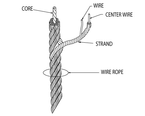
Wire rope and cable are each considered a “machine”. The configuration and method of manufacture combined with the proper selection of material when designed for a specific purpose enables a wire rope or cable to transmit forces, motion and energy in some predetermined manner and to some desired end.
Two or more wires concentrically laid around a center wire is called a strand. It may consist of one or more layers. Typically, the number of wires in a strand is 7, 19 or 37. A group of strands laid around a core would be called a cable or wire rope. In terms of product designation, 7 strands with 19 wires in each strand would be a 7×19 cable: 7 strands with 7 wires in each strand would be a 7×7 cable.
Materials Different applications for wire rope present varying demands for strength, abrasion and corrosion resistance. In order to meet these requirements, wire rope is produced in a number of different materials.
Stainless Steel This is used where corrosion is a prime factor and the cost increase warrants its use. The 18% chromium, 8% nickel alloy known as type 302 is the most common grade accepted due to both corrosion resistance and high strength. Other types frequently used in wire rope are 304, 305, 316 and 321, each having its specific advantage over the other. Type 305 is used where non-magnetic properties are required, however, there is a slight loss of strength.
Galvanized Carbon Steel This is used where strength is a prime factor and corrosion resistance is not great enough to require the use of stainless steel. The lower cost is usually a consideration in the selection of galvanized carbon steel. Wires used in these wire ropes are individually coated with a layer of zinc which offers a good measure of protection from corrosive elements.
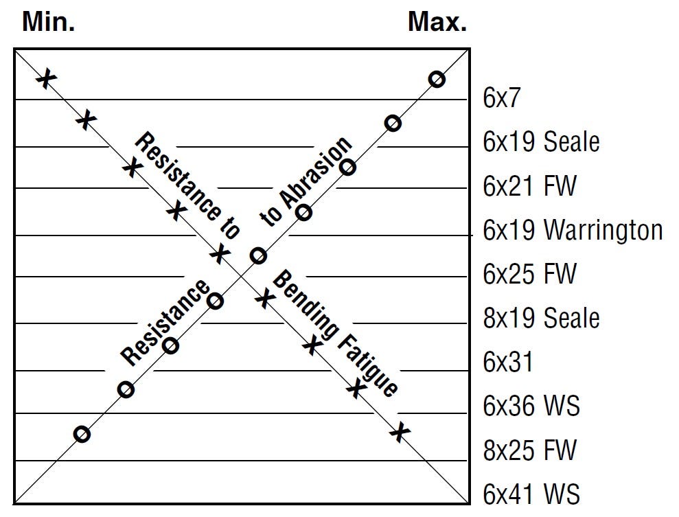
Cable Construction The greater the number of wires in a strand or cable of a given diameter, the more flexibility it has. A 1×7 or a 1×19 strand, having 7 and 19 wires respectively, is used principally as a fixed member, as a straight linkage, or where flexing is minimal.
Cables designed with 3×7, 7×7 and 7×19 construction provide for increasing degrees of flexibility but decreased abrasion resistance. These designs would be incorporated where continuous flexing is a requirement.
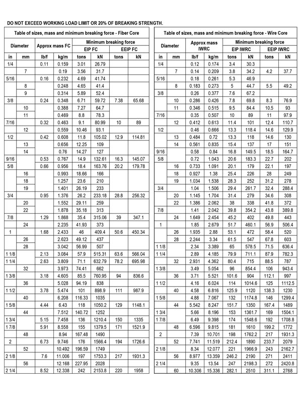
Selecting Wire Rope When selecting a wire rope to give the best service, there are four requirements which should be given consideration. A proper choice is made by correctly estimating the relative importance of these requirements and selecting a rope which has the qualities best suited to withstand the effects of continued use. The rope should possess:Strength sufficient to take care of the maximum load that may be applied, with a proper safety factor.
Strength Wire rope in service is subjected to several kinds of stresses. The stresses most frequently encountered are direct tension, stress due to acceleration, stress due to sudden or shock loads, stress due to bending, and stress resulting from several forces acting at one time. For the most part, these stresses can be converted into terms of simple tension, and a rope of approximately the correct strength can be chosen. As the strength of a wire rope is determined by its, size, grade and construction, these three factors should be considered.
Safety Factors The safety factor is the ratio of the strength of the rope to the working load. A wire rope with a strength of 10,000 pounds and a total working load of 2,000 pounds would be operating with a safety factor of five.
It is not possible to set safety factors for the various types of wire rope using equipment, as this factor can vary with conditions on individual units of equipment.
The proper safety factor depends not only on the loads applied, but also on the speed of operation, shock load applied, the type of fittings used for securing the rope ends, the acceleration and deceleration, the length of rope, the number, size and location of sheaves and drums, the factors causing abrasion and corrosion and the facilities for inspection.
Fatigue Fatigue failure of the wires in a wire rope is the result of the propagation of small cracks under repeated applications of bending loads. It occurs when ropes operate over comparatively small sheaves or drums. The repeated bending of the individual wires, as the rope bends when passing over the sheaves or drums, and the straightening of the individual wires, as the rope leaves the sheaves or drums, causing fatigue. The effect of fatigue on wires is illustrated by bending a wire repeatedly back and forth until it breaks.
The best means of preventing early fatigue of wire ropes is to use sheaves and drums of adequate size. To increase the resistance to fatigue, a rope of more flexible construction should be used, as increased flexibility is secured through the use of smaller wires.
Abrasive Wear The ability of a wire rope to withstand abrasion is determined by the size, the carbon and manganese content, the heat treatment of the outer wires and the construction of the rope. The larger outer wires of the less flexible constructions are better able to withstand abrasion than the finer outer wires of the more flexible ropes. The higher carbon and manganese content and the heat treatment used in producing wire for the stronger ropes, make the higher grade ropes better able to withstand abrasive wear than the lower grade ropes.
Effects of Bending All wire ropes, except stationary ropes used as guys or supports, are subjected to bending around sheaves or drums. The service obtained from wire ropes is, to a large extent, dependent upon the proper choice and location of the sheaves and drums about which it operates.
A wire rope may be considered a machine in which the individual elements (wires and strands) slide upon each other when the rope is bent. Therefore, as a prerequisite to the satisfactory operation of wire rope over sheaves and drums, the rope must be properly lubricated.
Loss of strength due to bending is caused by the inability of the individual strands and wires to adjust themselves to their changed position when the rope is bent. Tests made by the National Institute of Standards and Technology show that the rope strength decreases in a marked degree as the sheave diameter grows smaller with respect to the diameter of the rope. The loss of strength due to bending wire ropes over the sheaves found in common use will not exceed 6% and will usually be about 4%.
The bending of a wire rope is accompanied by readjustment in the positions of the strands and wires and results in actual bending of the wires. Repetitive flexing of the wires develops bending loads which, even though well within the elastic limit of the wires, set up points of stress concentration.
The fatigue effect of bending appears in the form of small cracks in the wires at these over-stressed foci. These cracks propagate under repeated stress cycles, until the remaining sound metal is inadequate to withstand the bending load. This results in broken wires showing no apparent contraction of cross section.
Experience has established the fact that from the service view-point, a very definite relationship exists between the size of the individual outer wires of a wire rope and the size of the sheave or drum about which it operates. Sheaves and drums smaller than 200 times the diameter of the outer wires will cause permanent set in a heavily loaded rope. Good practice requires the use of sheaves and drums with diameters 800 times the diameter of the outer wires in the rope for heavily loaded fast-moving ropes.
It is impossible to give a definite minimum size of sheave or drum about which a wire rope will operate with satisfactory results, because of the other factors affecting the useful life of the rope. If the loads are light or the speed slow, smaller sheaves and drums can be used without causing early fatigue of the wires than if the loads are heavy or the speed is fast. Reverse bends, where a rope is bent in one direction and then in the opposite direction, cause excessive fatigue and should be avoided whenever possible. When a reverse bend is necessary larger sheaves are required than would be the case if the rope were bent in one direction only.
Stretch of Wire Rope The stretch of a wire rope under load is the result of two components: the structural stretch and the elastic stretch. Structural stretch of wire rope is caused by the lengthening of the rope lay, compression of the core and adjustment of the wires and strands to the load placed upon the wire rope. The elastic stretch is caused by elongation of the wires.
The structural stretch varies with the size of core, the lengths of lays and the construction of the rope. This stretch also varies with the loads imposed and the amount of bending to which the rope is subjected. For estimating this stretch the value of one-half percent, or .005 times the length of the rope under load, gives an approximate figure. If loads are light, one-quarter percent or .0025 times the rope length may be used. With heavy loads, this stretch may approach one percent, or .01 times the rope length.
The elastic stretch of a wire rope is directly proportional to the load and the length of rope under load, and inversely proportional to the metallic area and modulus of elasticity. This applies only to loads that do not exceed the elastic limit of a wire rope. The elastic limit of stainless steel wire rope is approximately 60% of its breaking strength and for galvanized ropes it is approximately 50%.
Preformed Wire Ropes Preformed ropes differ from the standard, or non-preformed ropes, in that the individual wires in the strands and the strands in the rope are preformed, or pre-shaped to their proper shape before they are assembled in the finished rope.
This, in turn, results in preformed wire ropes having the following characteristics:They can be cut without the seizings necessary to retain the rope structure of non-preformed ropes.
They are substantially free from liveliness and twisting tendencies. This makes installation and handling easier, and lessens the likelihood of damage to the rope from kinking or fouling. Preforming permits the more general use of Lang lay and wire core constructions.
Removal of internal stresses increase resistance to fatigue from bending. This results in increased service where ability to withstand bending is the important requirement. It also permits the use of ropes with larger outer wires, when increased wear resistance is desired.
Outer wires will wear thinner before breaking, and broken wire ends will not protrude from the rope to injure worker’s hands, to nick and distort adjacent wires, or to wear sheaves and drums. Because of the fact that broken wire ends do not porcupine, they are not as noticeable as they are in non-preformed ropes. This necessitates the use of greater care when inspecting worn preformed ropes, to determine their true condition.
Rope diameter is specified by the user and is generally given in the equipment manufacturer’s instruction manual accompanying the machine on which the rope is to be used.
Rope diameters are determined by measuring the circle that just touches the extreme outer limits of the strands— that is, the greatest dimension that can be measured with a pair of parallel-jawed calipers or machinist’s caliper square. A mistake could be made by measuring the smaller dimension.
The right way to unreel.To unreel wire rope from a heavy reel, place a shaft through the center and jack up the reel far enough to clear the floor and revolve easily. One person holds the end of the rope and walks a straight line away from the reel, taking the wire rope off the top of the reel. A second person regulates the speed of the turning reel by holding a wood block against the flange as a brake, taking care to keep slack from developing on the reel, as this can easily cause a kink in the rope. Lightweight reels can be properly unreeled using a vertical shaft; the same care should be taken to keep the rope taut.
The wrong way to unreel.If a reel of wire rope is laid on its flange with its axis vertical to the floor and the rope unreeled by throwing off the turns, spirals will occur and kinks are likely to form in the rope. Wire rope always should be handled in a way that neither twists nor unlays it. If handled in a careless manner, reverse bends and kinks can easily occur.
The right way to uncoil.There is only one correct way to uncoil wire rope. One person must hold the end of the rope while a second person rolls the coil along the floor, backing away. The rope is allowed to uncoil naturally with the lay, without spiraling or twisting. Always uncoil wire rope as shown.
The wrong way to uncoil.If a coil of wire rope is laid flat on the floor and uncoiled by pulling it straight off, spirals will occur and kinking is likely. Torsions are put into the rope by every loop that is pulled off, and the rope becomes twisted and unmanageable. Also, wire rope cannot be uncoiled like hemp rope. Pulling one end through the middle of the coil will only result in kinking.
Great stress has been placed on the care that should be taken to avoid kinks in wire rope. Kinks are places where the rope has been unintentionally bent to a permanent set. This happens where loops are pulled through by tension on the rope until the diameter of the loop is only a few inches. They also are caused by bending a rope around a sheave having too severe a radius. Wires in the strands at the kink are permanently damagedand will not give normal service, even after apparent “re-straightening.”
When wire rope is wound onto a sheave or drum, it should bend in the manner in which it was originally wound. This will avoid causing a reverse bend in the rope. Always wind wire rope from the top of the one reel onto the top of the other.Also acceptable, but less so, is re-reeling from the bottom of one reel to the bottom of another. Re-reeling also may be done with reels having their shafts vertical, but extreme care must be taken to ensure that the rope always remains taut. It should never be allowed to drop below the lower flange of the reel. A reel resting on the floor with its axis horizontal may also be rolled along the floor to unreel the rope.
Wire rope should be attached at the correct location on a flat or smooth-faced drum, so that the rope will spool evenly, with the turns lying snugly against each other in even layers. If wire rope is wound on a smooth-face drum in the wrong direction, the turns in the first layer of rope will tend to spread apart on the drum. This results in the second layer of rope wedging between the open coils, crushing and flattening the rope as successive layers are spooled.
A simple method of determining how a wire rope should be started on a drum. The observer stands behind the drum, with the rope coming towards him. Using the right hand for right-lay wire rope, and the left hand for left lay wire rope, the clenched fist denotes the drum, the extended index finger the oncoming rope.
Clips are usually spaced about six wire rope diameters apart to give adequate holding power. They should be tightened before the rope is placed under tension. After the load is placed on the rope, tighten the clips again to take care of any lessening in rope diameter caused by tension of the load. A wire rope thimble should be used in the eye of the loop to prevent kinking.
U-bolt Clips.There is only one correct method for attaching U-bolt clips to wire rope ends, as shown in TheRightWayimage below. The base of the clip bears on the live end of the rope; the “U” of the bolt bears on the dead end.
Compare this with the incorrect methods. Five of the six clips shown are incorrectly attached—only the center clip in the top view is correct. When the “U” of the clip bears on the live end of the rope, there is a possibility of the rope being cut or kinked, with subsequent failure.
Proper seizing and cutting operations are not difficult to perform, and they ensure that the wire rope will meet the user’s performance expectations. Proper seizings must be applied on both sides of the place where the cut is to be made. In a wire rope, carelessly or inadequately seized ends may become distorted and flattened, and the strands may loosen. Subsequently, when the rope is operated, there may be an uneven distribution of loads to the strands; a condition that will significantly shorten the life of the rope.
Either of the following seizing methods is acceptable. Method No. 1 is usually used on wire ropes over one inch in diameter. Method No. 2 applies to ropes one inch and under.
Method No. 1: Place one end of the seizing wire in the valley between two strands. Then turn its long end at right angles to the rope and closely and tightly wind the wire back over itself and the rope until the proper length of seizing has been applied. Twist the two ends of the wire together, and by alternately pulling and twisting, draw the seizing tight.
The Seizing Wire. The seizing wire should be soft or annealed wire or strand. Seizing wire diameter and the length of the seize will depend on the diameter of the wire rope. The length of the seizing should never be less than the diameter of the rope being seized.
Proper end seizing while cutting and installing, particularly on rotation-resistant ropes, is critical. Failure to adhere to simple precautionary measures may cause core slippage and loose strands, resulting in serious rope damage. Refer to the table below ("Suggested Seizing Wire Diameters") for established guidelines. If core protrusion occurs beyond the outer strands, or core retraction within the outer strands, cut the rope flush to allow for proper seizing of both the core and outer strands.
The majority of wire rope problems occurring during operation actually begin during installation, when the rope is at its greatest risk of being damaged. Proper installation procedures are vital in the protection and performance of wire rope products.
Until the rope is installed it should be stored on a rack, pallet or reel stand in a dry, well-ventilated storage shed or building. Tightly sealed and unheated structures should be avoided as condensation between rope strands may occur and cause corrosion problems. If site conditions demand outside storage, cover the rope with waterproof material and place the reel or coil on a support platform to keep it from coming directly in contact with the ground.
While lubrication is applied during the manufacturing process, the wire rope must still be protected by additional lubrication once it is installed. Lubricants will dry out over a period of time and corrosion from the elements will occur unless measures are taken to prevent this from happening. When the machine becomes idle for a period of time, apply a protective coating of lubricant to the wire rope. Moisture (dew, rain, and snow) trapped between strands and wires will create corrosion if the rope is unprotected. Also apply lubricant to each layer of wire rope on a drum because moisture trapped between layers will increase the likelihood of corrosion.
Always use the nominal diameter as specified by the equipment manufacturer. Using a smaller diameter rope will cause increased stresses on the rope and the probability of a critical failure is increased if the rated breaking strength does not match that of the specified diameter. Using a larger diameter rope leads to shorter service life as the rope is pinched in the sheave and drum grooves which were originally designed for a smaller diameter rope. Just as using a different diameter rope can create performance problems, so can the use of an excessively undersized or oversized rope.
Measure the wire rope using a parallel-jawed caliper as discussed in Measuring Rope Diameter at the top of this page. If the rope is the wrong size or outside the recommended tolerance, return the rope to the wire rope supplier. It is never recommended nor permitted by federal standards to operate cranes with the incorrect rope diameter. Doing so will affect the safety factor or reduce service life and damage the sheaves and drum. Note that in a grooved drum application, the pitch of the groove may be designed for the rope’s nominal diameter and not the actual diameter as permitted by federal standards.
Wire rope can be permanently damaged by improper unreeling or uncoiling practices. The majority of wire rope performance problems start here.Improper unreeling practices lead to premature rope replacement, hoisting problems and rope failure.
Place the payout reel as far away from the boom tip as is practical, moving away from the crane chassis. Never place the payout reel closer to the crane chassis than the boom point sheave. Doing so may introduce a reverse bend into the rope and cause spooling problems. Follow the guidelines highlighted under Unreeling and Uncoiling and Drum Winding. Take care to determine whether the wire rope will wind over or under the drum before proceeding. If the wire rope supplier secured the end of the rope to the reel by driving a nail through the strands, ask that in the future a U-bolt or other nondestructive tie-down method be used; nails used in this manner damage the rope.
Take extra precaution when installing lang lay, rotation-resistant, flattened strand or compacted ropes. Loss of twist must be avoided to prevent the strands from becoming loosened, causing looped wire problems.
The end of the rope must be securely and evenly attached to the drum anchorage point by the method recommended by the equipment manufacturer. Depending on the crane’s regulatory requirements, at least two to three wraps must remain on the drum as dead wraps when the rope is unwound during normal operations. Locate the dead end rope anchorage point on the drum in relation to the direction of the lay of the rope. Do not use an anchorage point that does not correspond with the rope lay. Mismatching rope lay and anchorage point will cause the wraps to spread apart from each other and allow the rope to cross over on the drum. Very gappy winding will occur resulting in crushing damage in multilayer applications.
Back tension must be continually applied to the payout reel and the crewman installing the rope must proceed at a slow and steady pace whether the drum is smooth or grooved.Regardless of the benefits of a grooved drum, tension must be applied to ensure proper spooling. An improperly installed rope on a grooved drum will wear just as quickly as an improperly installed rope on a smooth drum. If a wire rope is poorly wound and as a result jumps the grooves, it will be crushed and cut under operating load conditions where it crosses the grooves.
Every wrap on the first or foundation layer must be installed very tightly and be without gaps. Careless winding results in poor spooling and will eventually lead to short service life. The following layers of rope must lay in the grooves formed between adjacent turns of the preceding layer of rope. If any type of overwind or cross-winding occurs at this stage of installation and is not corrected immediately, poor spooling and crushing damage will occur.
On a multilayer spooling drum be sure that the last layer remains at least two rope diameters below the drum flange top. Do not use a longer length than is required because the excess wire rope will cause unnecessary crushing and may jump the flange. Loose wraps that occur at any time must be corrected immediately to prevent catastrophic rope failure.
The use of a mallet is acceptable to ensure tight wraps, however a steel-faced mallet should be covered with plastic or rubber to prevent damage to the rope wires and strands.
Rotation-resistant ropes of all constructions require extra care in handling to prevent rope damage during installation. The lay length of a rotation-resistant rope must not be disturbed during the various stages of installation. By introducing twist or torque into the rope, core slippage may occur—the outer strands become shorter in length, the core slips and protrudes from the rope. In this condition the outer strands become over- loaded because the core is no longer taking its designed share of the load. Conversely, when torque is removed from a rotation-resistant rope core slippage can also occur. The outer strands become longer and the inner layers or core become overloaded, reducing service life and causing rope failure.
The plain end of a wire rope must be properly secured. If the entire cross section of the rope is not firmly secured, core slippage may occur, causing the core to pull inside the rope’s end and allowing it to protrude elsewhere, either through the outer strands (popped core) or out the other end of the line. The outer layer of the outside strands may also become overloaded as there is no complete core-to-strand support.
Secure the ends of the rope with either seizing or welding methods as recommended under Seizing Wire Rope. It is imperative that the ends be held together tightly and uniformly throughout the entire installation procedure, including attaching the end through the wedge socket and the drum dead end wedge
When installing a new line, connect the old line to the new line by using a swivel-equipped cable snake or Chinese finger securely attached to the rope ends. The connection between the ropes during change-out must be very strong and prevent torque from the old rope being transferred into the new rope.Welding ropes together or using a cable snake without the benefit of a swivel increases the likelihood of introducing torque into the new rope. A swivel-equipped cable snake is not as easy as welding the ropes, but this procedure can be mastered with a little patience and practice.
In stricter senses, the term wire rope refers to a diameter larger than 9.5 mm (3⁄8 in), with smaller gauges designated cable or cords.wrought iron wires were used, but today steel is the main material used for wire ropes.
Historically, wire rope evolved from wrought iron chains, which had a record of mechanical failure. While flaws in chain links or solid steel bars can lead to catastrophic failure, flaws in the wires making up a steel cable are less critical as the other wires easily take up the load. While friction between the individual wires and strands causes wear over the life of the rope, it also helps to compensate for minor failures in the short run.
Wire ropes were developed starting with mining hoist applications in the 1830s. Wire ropes are used dynamically for lifting and hoisting in cranes and elevators, and for transmission of mechanical power. Wire rope is also used to transmit force in mechanisms, such as a Bowden cable or the control surfaces of an airplane connected to levers and pedals in the cockpit. Only aircraft cables have WSC (wire strand core). Also, aircraft cables are available in smaller diameters than wire rope. For example, aircraft cables are available in 1.2 mm (3⁄64 in) diameter while most wire ropes begin at a 6.4 mm (1⁄4 in) diameter.suspension bridges or as guy wires to support towers. An aerial tramway relies on wire rope to support and move cargo overhead.
Modern wire rope was invented by the German mining engineer Wilhelm Albert in the years between 1831 and 1834 for use in mining in the Harz Mountains in Clausthal, Lower Saxony, Germany.chains, such as had been used before.
Wilhelm Albert"s first ropes consisted of three strands consisting of four wires each. In 1840, Scotsman Robert Stirling Newall improved the process further.John A. Roebling, starting in 1841suspension bridge building. Roebling introduced a number of innovations in the design, materials and manufacture of wire rope. Ever with an ear to technology developments in mining and railroading, Josiah White and Erskine Hazard, principal ownersLehigh Coal & Navigation Company (LC&N Co.) — as they had with the first blast furnaces in the Lehigh Valley — built a Wire Rope factory in Mauch Chunk,Pennsylvania in 1848, which provided lift cables for the Ashley Planes project, then the back track planes of the Summit Hill & Mauch Chunk Railroad, improving its attractiveness as a premier tourism destination, and vastly improving the throughput of the coal capacity since return of cars dropped from nearly four hours to less than 20 minutes. The decades were witness to a burgeoning increase in deep shaft mining in both Europe and North America as surface mineral deposits were exhausted and miners had to chase layers along inclined layers. The era was early in railroad development and steam engines lacked sufficient tractive effort to climb steep slopes, so incline plane railways were common. This pushed development of cable hoists rapidly in the United States as surface deposits in the Anthracite Coal Region north and south dove deeper every year, and even the rich deposits in the Panther Creek Valley required LC&N Co. to drive their first shafts into lower slopes beginning Lansford and its Schuylkill County twin-town Coaldale.
The German engineering firm of Adolf Bleichert & Co. was founded in 1874 and began to build bicable aerial tramways for mining in the Ruhr Valley. With important patents, and dozens of working systems in Europe, Bleichert dominated the global industry, later licensing its designs and manufacturing techniques to Trenton Iron Works, New Jersey, USA which built systems across America. Adolf Bleichert & Co. went on to build hundreds of aerial tramways around the world: from Alaska to Argentina, Australia and Spitsbergen. The Bleichert company also built hundreds of aerial tramways for both the Imperial German Army and the Wehrmacht.
In the last half of the 19th century, wire rope systems were used as a means of transmitting mechanical powercable cars. Wire rope systems cost one-tenth as much and had lower friction losses than line shafts. Because of these advantages, wire rope systems were used to transmit power for a distance of a few miles or kilometers.
Steel wires for wire ropes are normally made of non-alloy carbon steel with a carbon content of 0.4 to 0.95%. The very high strength of the rope wires enables wire ropes to support large tensile forces and to run over sheaves with relatively small diameters.
In the mostly used parallel lay strands, the lay length of all the wire layers is equal and the wires of any two superimposed layers are parallel, resulting in linear contact. The wire of the outer layer is supported by two wires of the inner layer. These wires are neighbors along the whole length of the strand. Parallel lay strands are made in one operation. The endurance of wire ropes with this kind of strand is always much greater than of those (seldom used) with cross lay strands. Parallel lay strands with two wire layers have the construction Filler, Seale or Warrington.
In principle, spiral ropes are round strands as they have an assembly of layers of wires laid helically over a centre with at least one layer of wires being laid in the opposite direction to that of the outer layer. Spiral ropes can be dimensioned in such a way that they are non-rotating which means that under tension the rope torque is nearly zero. The open spiral rope consists only of round wires. The half-locked coil rope and the full-locked coil rope always have a centre made of round wires. The locked coil ropes have one or more outer layers of profile wires. They have the advantage that their construction prevents the penetration of dirt and water to a greater extent and it also protects them from loss of lubricant. In addition, they have one further very important advantage as the ends of a broken outer wire cannot leave the rope if it has the proper dimensions.
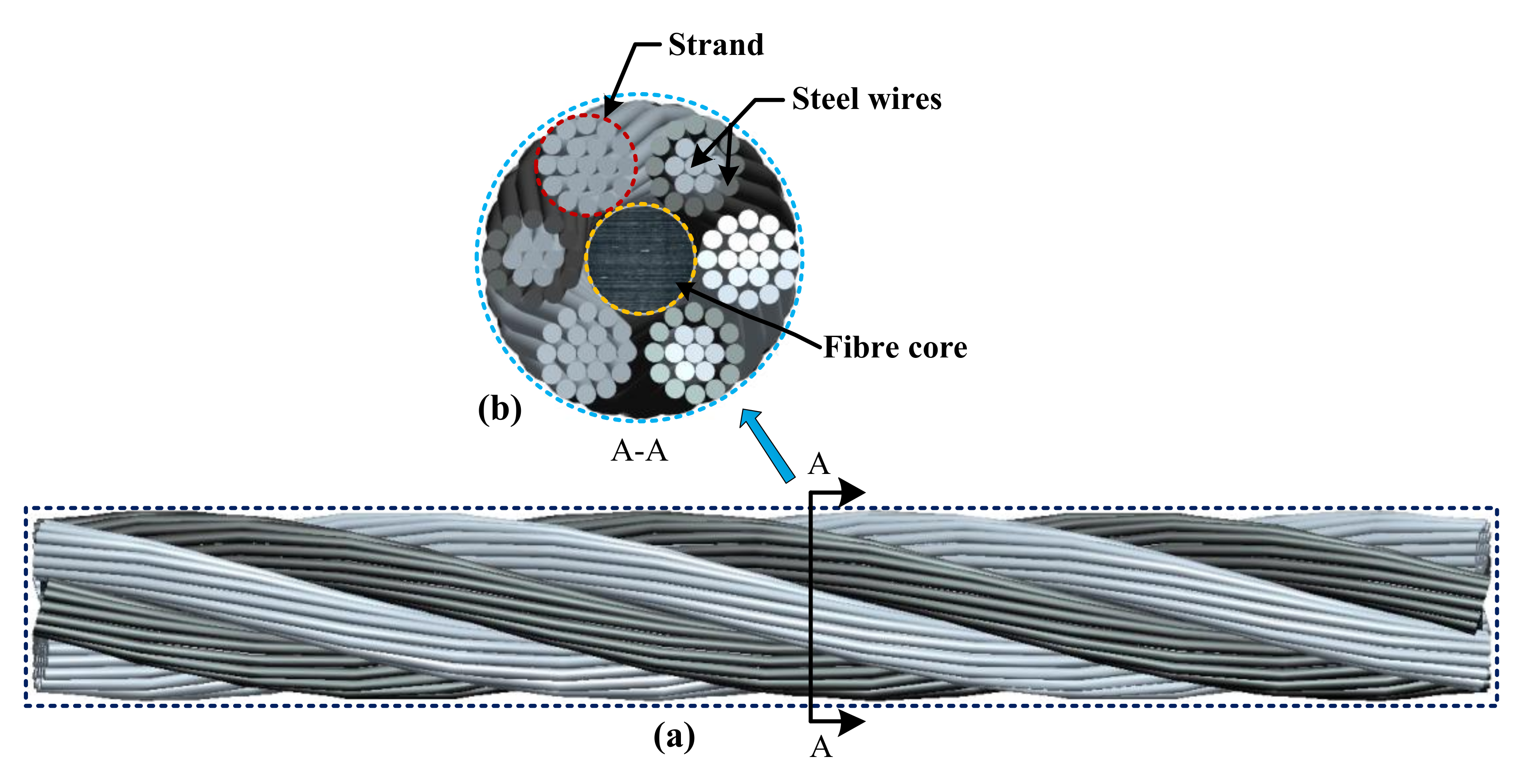
Stranded ropes are an assembly of several strands laid helically in one or more layers around a core. This core can be one of three types. The first is a fiber core, made up of synthetic material or natural fibers like sisal. Synthetic fibers are stronger and more uniform but cannot absorb much lubricant. Natural fibers can absorb up to 15% of their weight in lubricant and so protect the inner wires much better from corrosion than synthetic fibers do. Fiber cores are the most flexible and elastic, but have the downside of getting crushed easily. The second type, wire strand core, is made up of one additional strand of wire, and is typically used for suspension. The third type is independent wire rope core (IWRC), which is the most durable in all types of environments.ordinary lay rope if the lay direction of the wires in the outer strands is in the opposite direction to the lay of the outer strands themselves. If both the wires in the outer strands and the outer strands themselves have the same lay direction, the rope is called a lang lay rope (from Dutch langslag contrary to kruisslag,Regular lay means the individual wires were wrapped around the centers in one direction and the strands were wrapped around the core in the opposite direction.
Multi-strand ropes are all more or less resistant to rotation and have at least two layers of strands laid helically around a centre. The direction of the outer strands is opposite to that of the underlying strand layers. Ropes with three strand layers can be nearly non-rotating. Ropes with two strand layers are mostly only low-rotating.
Stationary ropes, stay ropes (spiral ropes, mostly full-locked) have to carry tensile forces and are therefore mainly loaded by static and fluctuating tensile stresses. Ropes used for suspension are often called cables.
Track ropes (full locked ropes) have to act as rails for the rollers of cabins or other loads in aerial ropeways and cable cranes. In contrast to running ropes, track ropes do not take on the curvature of the rollers. Under the roller force, a so-called free bending radius of the rope occurs. This radius increases (and the bending stresses decrease) with the tensile force and decreases with the roller force.
Wire rope slings (stranded ropes) are used to harness various kinds of goods. These slings are stressed by the tensile forces but first of all by bending stresses when bent over the more or less sharp edges of the goods.
Technical regulations apply to the design of rope drives for cranes, elevators, rope ways and mining installations. Factors that are considered in design include:
Donandt force (yielding tensile force for a given bending diameter ratio D/d) - strict limit. The nominal rope tensile force S must be smaller than the Donandt force SD1.
The wire ropes are stressed by fluctuating forces, by wear, by corrosion and in seldom cases by extreme forces. The rope life is finite and the safety is only ensured by inspection for the detection of wire breaks on a reference rope length, of cross-section loss, as well as other failures so that the wire rope can be replaced before a dangerous situation occurs. Installations should be designed to facilitate the inspection of the wire ropes.
Lifting installations for passenger transportation require that a combination of several methods should be used to prevent a car from plunging downwards. Elevators must have redundant bearing ropes and a safety gear. Ropeways and mine hoistings must be permanently supervised by a responsible manager and the rope must be inspected by a magnetic method capable of detecting inner wire breaks.
The end of a wire rope tends to fray readily, and cannot be easily connected to plant and equipment. There are different ways of securing the ends of wire ropes to prevent fraying. The common and useful type of end fitting for a wire rope is to turn the end back to form a loop. The loose end is then fixed back on the wire rope. Termination efficiencies vary from about 70% for a Flemish eye alone; to nearly 90% for a Flemish eye and splice; to 100% for potted ends and swagings.
When the wire rope is terminated with a loop, there is a risk that it will bend too tightly, especially when the loop is connected to a device that concentrates the load on a relatively small area. A thimble can be installed inside the loop to preserve the natural shape of the loop, and protect the cable from pinching and abrading on the inside of the loop. The use of thimbles in loops is industry best practice. The thimble prevents the load from coming into direct contact with the wires.
A wire rope clip, sometimes called a clamp, is used to fix the loose end of the loop back to the wire rope. It usually consists of a U-bolt, a forged saddle, and two nuts. The two layers of wire rope are placed in the U-bolt. The saddle is then fitted to the bolt over the ropes (the saddle includes two holes to fit to the U-bolt). The nuts secure the arrangement in place. Two or more clips are usually used to terminate a wire rope depending on the diameter. As many as eight may be needed for a 2 in (50.8 mm) diameter rope.
The mnemonic "never saddle a dead horse" means that when installing clips, the saddle portion of the assembly is placed on the load-bearing or "live" side, not on the non-load-bearing or "dead" side of the cable. This is to protect the live or stress-bearing end of the rope against crushing and abuse. The flat bearing seat and extended prongs of the body are designed to protect the rope and are always placed against the live end.
An eye splice may be used to terminate the loose end of a wire rope when forming a loop. The strands of the end of a wire rope are unwound a certain distance, then bent around so that the end of the unwrapped length forms an eye. The unwrapped strands are then plaited back into the wire rope, forming the loop, or an eye, called an eye splice.
A Flemish eye, or Dutch Splice, involves unwrapping three strands (the strands need to be next to each other, not alternates) of the wire and keeping them off to one side. The remaining strands are bent around, until the end of the wire meets the "V" where the unwrapping finished, to form the eye. The strands kept to one side are now re-wrapped by wrapping from the end of the wire back to the "V" of the eye. These strands are effectively rewrapped along the wire in the opposite direction to their original lay. When this type of rope splice is used specifically on wire rope, it is called a "Molly Hogan", and, by some, a "Dutch" eye instead of a "Flemish" eye.
Swaging is a method of wire rope termination that refers to the installation technique. The purpose of swaging wire rope fittings is to connect two wire rope ends together, or to otherwise terminate one end of wire rope to something else. A mechanical or hydraulic swager is used to compress and deform the fitting, creating a permanent connection. Threaded studs, ferrules, sockets, and sleeves are examples of different swaged terminations.
A wedge socket termination is useful when the fitting needs to be replaced frequently. For example, if the end of a wire rope is in a high-wear region, the rope may be periodically trimmed, requiring the termination hardware to be removed and reapplied. An example of this is on the ends of the drag ropes on a dragline. The end loop of the wire rope enters a tapered opening in the socket, wrapped around a separate component called the wedge. The arrangement is knocked in place, and load gradually eased onto the rope. As the load increases on the wire rope, the wedge become more secure, gripping the rope tighter.
Poured sockets are used to make a high strength, permanent termination; they are created by inserting the wire rope into the narrow end of a conical cavity which is oriented in-line with the intended direction of strain. The individual wires are splayed out inside the cone or "capel", and the cone is then filled with molten lead-antimony-tin (Pb80Sb15Sn5) solder or "white metal capping",zincpolyester resin compound.
Donald Sayenga. "Modern History of Wire Rope". History of the Atlantic Cable & Submarine Telegraphy (atlantic-cable.com). Archived from the original on 3 February 2014. Retrieved 9 April 2014.

Wire ropes can be seen everywhere around us, they are made of strands or bundles of individual wires constructed around an independent core, suitable for construction, industrial, fitness, commercial, architectural, agricultural, and marine rigging applications.
Wire rod is made from high carbon steel wires(0.35 to 0.85 percent carbon) in a hot rolling process of a required diameter, usually from 5.5mm to 8 mm.
Wire rod is drawn to the required diameter by the 1st drawing machine after descaling dust and rust, adding mechanical properties suitable for application.
Positioning the wires different or the same size lay in multiple layers and same direction, or cross lay and diameter is maintained by one-third of the rope size.
So in theory, it is very simple to manufacture wire ropes. However there are many more details that must be closely monitored and controlled, and this requires time and experienced personnel since it is a super complicated project you cannot imagine.

Wire ropes are widely employed components in diverse areas, such as in industrial production, tourist cable cars, mining, metallurgy, shipbuilding, and elevators. Wire rope is a heavily loaded component, and long-term continuous operation eventually result in corrosion, wear, broken wires, loose wires, and fatigue, which decrease the loading strength of the rope, and can cause accidents, resulting in property damage and injury [1]. The traditional damage detection method is artificial visual inspection, which is a low efficiency, time-consuming, and unreliable method [1]. The development of a fast, non-destructive, and automatic detection technology is therefore necessary.
Wire rope defects include three main types: the loss of metallic area (LMA), local faults (FLs), and structural faults (SFs). The main non-destructive testing (NDT) methods employed for wire rope inspection include electromagnetic detection, ultrasonic guided wave (UGW) evaluation, radiation testing, eddy current inspection, and optical detection [1]. However, designing a precise detection device that can quantitatively determine the characteristics of defects, such as the number of broken wires, remains problematic, particularly when operating in severe environments [2].
The UGW method has been shown to provide a detection speed that is faster than other methods, but the method demonstrates a low anti-interference ability and suffers from strong background noise [3,4,5,6,7]. Treyssède and Laguerre’s [3] applied the transmission characteristics of UGW for wire rope testing. The researchers developed a semi-analytical finite element method, and calculated the optimal excitation and receiving sites. This approach provided a wave dispersion curve for spiral steel rope. Vanniamparambil [4] proposed a novel detection method that combined three technologies: UGW, acoustic emission techniques, and digital image processing. Xu [7] evaluated the detection precision of the UGW method for wire rope defects obtained at different frequencies, showing that wire ropes at higher frequencies had longer recovery lengths for their elastic waves. Raisuitis [5] investigated the propagation of UGWs along composite multi-wire ropes with various types of acoustic contacts between neighboring wires and the plastic core. Tse and Rostami [6] investigated the efficiency of employing the magnetostriction of ferromagnetic materials in conjunction with the UGW method for wire rope defect inspection, and the location and severity of defects were approximately identified and characterized using the short-time Fourier transform and wavelet analysis. Other detection methods, such as radiation testing [8] and eddy current inspection [9], have not been applied to wire rope inspection to a large extent.
Electromagnetic detection methods are commonly employed for the NDT of wire rope [2]. The basic principle behind wire rope electromagnetic detection is illustrated in Figure 1. The lower permeability of the air leads to magnetic field leakage (MFL) from the rope defect, and the strength of the MFL can be obtained from an appropriately designed magnetic detection device. In terms of the type of excitation source employed, electromagnetic detection can be divided according to the use of a coil [10,11] or a permanent magnet [12,13,14,15,16,17] for generating a magnetic field. Modified main-flux equipment has been developed for wire rope inspection, which induced changes in the electromagnetic field strength owing to the leakage field derived from defects in various large-diameter wire ropes [10]. Other researchers [11] employed a pair of saddle coils for the magnetization of a steel track rope, and this system was applied to detect small, inner flaws in the rope. Permanent magnets have been employed in a saddle structure to saturate wire rope in a uniform magnetic field [14,15,16,17]. Wang et al. [12] investigated the effect of excitation distance and the lift-off distance between the sensors and the wire rope surface on the detection precision. The researchers accordingly modified the magnetic circuit of the detector to restrain the impact of fluctuations in the sensor lift-off distance. Xu et al. [18] developed a magnetic excitation model. Based on this model, the researchers established design criteria for the size of the excitation structure, proposed a theoretical framework for the excitation structure size based on numerical analysis, and adjusted the theoretical design using finite element analysis (FEA).
Obtaining a precise MFL signal is the most important aspect for the accurate electromagnetic NDT of wire rope. For MFL signal acquisition, a commonly employed in-service NDT method utilizes an induction coil [10,17], Hall effect sensor [14,18,19,20,21], giant magnetoresistive (GMR) sensor [11,22], and tunnel magnetoresistive (TMR) sensor [23]. Jomdecha and Prateepasen [10] modified a conventional induction coil into a coil array that densely covered the wire rope to acquire the MFL signal. Wang and Tian [14] utilized FEA to address the problems associated with the weak MFL signals derived from small defects, and they investigated the gathered magnetism of the magnetization rope. They designed a detector with an annular pole polymagnet on one side using Hall elements as inductors. This detection system was able to capture weak MFL signals within the strong magnetic field. Xu and Wang [18] developed an online modular-detector NDT system using a Hall effect sensor that successfully detected inner broken wires. The researchers also presented three filtering algorithms. Detectors based on Hall effect sensor arrays have been widely applied for NDT under strong magnetic field conditions [19,20,21]. Cao [19] created an image from the defect data which was obtained by Hall sensors array, and applied digital image processing to extract and detect defect characteristics. Zhang et al. [20] employed signal processing to suppress the effect of lift-off distance, and applied statistical processing to distinguish different types of defects and to obtain binary image data describing the spatial extent of defects. Zhang et al. [21] applied a space filter to suppress the texture of strand waves after obtaining MFL gray-level images of wire rope defects, and the image spectrum texture was extracted as the characteristic vector used for recognition. GMR sensors have been employed for MFL signal acquisition because of their high sensitivity, high precision, and small size. GMR sensors were placed into a sensor array and densely distributed on the wire rope surface in a manner similar to that employed in a Hall effect sensor application [11]. Zhang and Tan [22] utilized the high sensitivity of a GMR sensor to develop a detection technique based on remanence magnetization, which combined the benefits of a simple structure and high detection speed with high precision. Wu et al. [23] demonstrated that TMR sensors can be applied to detect small discontinuities on a wire rope surface.
MFL signals contain a variety of distinct noise signals, which makes the development of an efficient de-noising algorithm challenging work. Currently, a number of noise reduction algorithms are commonly employed, including wavelet analysis de-noising, low-pass filter, notch filter [21], adaptive filter [20], morphological filter [24], and a de-noising algorithm based on compressed sensing (CS) [22]. Zhang et al. [20] applied digital image processing to develop a space filter for smoothing the defects in an MFL signal image. Zhang et al. [21] proposed a baseline estimation algorithm to suppress the effect of undulations in the lift-off distance and an adaptive notch filtering algorithm to filter the strand wave for increasing the signal-to-noise ratio. Zhang and Tan [22] utilized wavelet multi-resolution analysis to eliminate the baseline of the signal. Their work was based on the CS wavelet de-noising algorithm, and they calculated the best sparse transform expression to completely filter out the noise. Tian et al. combined the wavelet transform and the morphological transform to create a morphological filter algorithm that suppressed the interference associated with the baseline drift in the wire rope signal. Artificial neural networks have been widely applied to realize the quantitative detection of wire rope defects. These networks operate much like back propagation (BP) neural networks employed by a number of researchers [20,21,22]. However, BP neural networks suffer from some limitations and shortcomings, such as poor generalization and slow convergence.
To overcome the disadvantages of existing detection devices, we developed a prototype device based on the RMF of a wire rope. This inspection method utilizes GMR sensors for excitation signal acquisition. After magnetizing the wire rope with permanent magnets, the GMR sensor array was utilized to obtain the RMF strength of the rope surface. This detection system is non-contact and non-invasive which prolongs the service life of test equipment. A novel filter algorithm based on the Hilbert-Huang transform (HHT) and compressed sensing wavelet filtering (CSWF) was developed to suppress the various system noises. The HHT was employed to remove the DC component of the signal and balance the sensor channels. CSWF was employed to suppress high-frequency noises and strand waves. Then, we applied digital image processing to create a binary image using a filter based on corrosion and expansion. Subsequently, defects were located and segmented within the gray-level image. Because an 18 GMR sensor array was employed, the resulting gray-level image included only 18 pixels in its circumference. Three spline interpolations were performed to improve the circumferential resolution of the gray-level image. Thirteen image characteristics comprising 6 image textures and seven invariant moments were extracted as defect feature vectors. A radial basis function (RBF) neural network, which is a fast-learning classification network that provides a global optimum, was adopted to quantitatively detect the number of broken wires in the rope. Experimental results demonstrate that, when the absolute limiting error for the detected number of broken wires is 2, the recognition rate is as high as 93.75% with an average recognition error of 0.7813 wires.

Formed by John Cooner in 1957 under the name of Service Cable and Wire with focus on specialty molded electrical cord sets and sales of fine and ultra-fine wire and cable constructions, Cooner Wire continues to excel world wide, as a premier supplier of high technology specialty wire, cable and cable assemblies.
Long term employees Patrick Weir and Steven Smith purchased Cooner Wire from the Cooner family in 1983 and continued to follow the successful direction of John Cooner in maintaining focus on the high technology, specialty wire and cable market. In 1984, Cooner Wire Interconnect Division was expanded and manufacturing was moved to Mexico.
As a pacesetter in the definitive specialty wire and cable industry, Cooner Wire has relied upon its continuing years of experience to help assist and solve complex electronic problems with their resource of experienced personnel. Cooner Wire continues to maintain worldwide recognition as the “go to” company for specialty wire and cable, and cable assembly products.
As a pacesetter in the definitive specialty wire and cable industry, Cooner Wire has relied upon their continuing years of experience to assist and solve complex electronic problems with their resource of experienced personnel. Cooner Wire has emerged as the cutting edge to the multilevel needs of national, corporate and private institutions world wide.
“It is the intent of Cooner Wire company to make available to our customers the knowledge and experience we have acquired through many successful years of producing application cables and accessories. It is our desire that, as much as possible, our customers be able to receive from Cooner Wire a product that meets their needs rather than manipulating their need to fit our product.

The steel strand 4 that adopts when twisting with the fingers the system steel cable forms through many steel wires 7 systems of twisting with the fingers, and the system of twisting with the fingers make friends with a material filling and heating, make the filler 6 of perfusion be full of the inside gap space of steel wire, thereby make steel strand also form the integral body of a sealing.
At last, make sealing steel cable that above-mentioned steps makes carry out undergauge through the tight wire stitcher 24 of roller type and handle, so that silk screen will seal steel cable parcel consolidation, and the cable diameter of having avoided the filler of inner filling to cause suddenlys change.The sealing steel cable 26 that has silk screen that makes is stored on the admission machine 27.
The silk screen mesh of braiding is a diamond shaped, and the major axis diagonal-size is between 7-9mm, and the steel wire diameter of braiding silk screen is in the 0.6mm-1.4mm scope, and the netting number of plies is the 1-3 layer.Be to obtain the compactibility of good pliability and rope body parcel, the twine thigh of silk screen adopts the many steel wires system of twisting with the fingers to form, and puies forward the difference of the gravity and the bailing frequency during netting according to the steel cable master, adopts the radical of twine thigh also inequality, between 8-24, selects.
At first, the sealing steel cable that has silk screen 26 that step 2 is made carries out the The pre-heat treatment (not shown), makes that the filler on the sealing steel cable reaches the sticking state that dissolves, and preheat temperature is decided according to the caking property of filler;
That adopts that elastomeric material makes steel cable is outer when protecting sealant; Its process chart is shown in Fig. 3 b; Steel cable after the preheating is through extruder 32; Extruder 32 will plastify good outer protect on the outer surface that coating is coated in silk screen after, steel cable integral body is carried out vulcanizing treatment through over cure line 37, other technical process is identical with the technical process that sealant is protected in the manufacturing of employing macromolecular material outward.
Then, steel cable is whole to carry out the press polish sizing through temperature control plug die 43, afterwards again through cold rinse bank 44 coolings; Feasible flexible oil pumping rope smooth outer surface, diameter is unified, reaches its use standard; So just, obtained the flexibility oil pumping rope 8 that the inventive method is made, its structure chart is as shown in Figure 5.
The multiply copper conductors is applied one deck high temperature resistance outward protect insulating barrier outward, to process communication conductor.Wherein, communication conductor requires low, the outer jacket high temperature resistance of resistivity, and tensile strength is big, and in drawing process, having good anti-fracture is insulating properties, has reliable work stability.
Shown in Fig. 1 a; The communication conductor 9 that step 1 is made is twisted into order wire strand 5; Through sth. made by twisting system machine 13, make order wire strand 5 twist with the fingers system with steel wire strand thigh 4 order wire strand 5, all the other technical process are identical with embodiment 1; With preparation sealing steel cable 3a, and make order wire strand 5 be positioned at the core of sealing steel cable 3a.
The subsequent technique process is identical with embodiment 1, and like this, just can obtain the flexibility oil pumping rope 8a with communication function of the inventive method manufacturing, its structure chart is shown in Fig. 5 a.


 8613371530291