
wire rope inspection standard for sale
If required UNIROPE® provides ON SITE INSPECTION SERVICE. Our factory trained inspection personnel will provide you with a full WRITTEN inspection report and a complete LISTING of all inspected slings in service at your plant or construction site. Where necessary we will proof-load the slings and issue a PROOF TEST CERTIFICATE. This service not only covers slings made from wire rope, but also slings made from chain and synthetic fibers.
The goal of a sling inspection is to evaluate the remaining strength in a sling, which has been used previously, to determine if it is suitable for continued use.
Specific inspection intervals and procedures are required by local safety regulations (e.g. in Ontario see OHSA) and by ASTM B30.9. The responsibility for having the inspection done is placed upon the SLING USER.
As a starting point, the same work practices which apply to all “working” wire ropes also apply to wire rope slings. Therefore, a good working knowledge of wire rope design and construction will not only be useful but essential in conducting a wire rope sling inspection.
Since a wire rope is a rather complex “machine”, no precise rules can be given to determine exactly when a wire rope sling should be replaced. There are many variables, and all must be considered.
Broken Wires: For 6-strand wire rope slings, 10 randomly distributed broken wires in one rope lay, or five broken wires in one strand of one rope lay. For Gator-Flex® and Tri-Flex® slings these same rules apply to each of the component ropes.
Metal Loss: Wear or scraping of one-third the original diameter of outside individual wires. This is quite difficult to determine on slings and you require some experience to perform this evaluation.
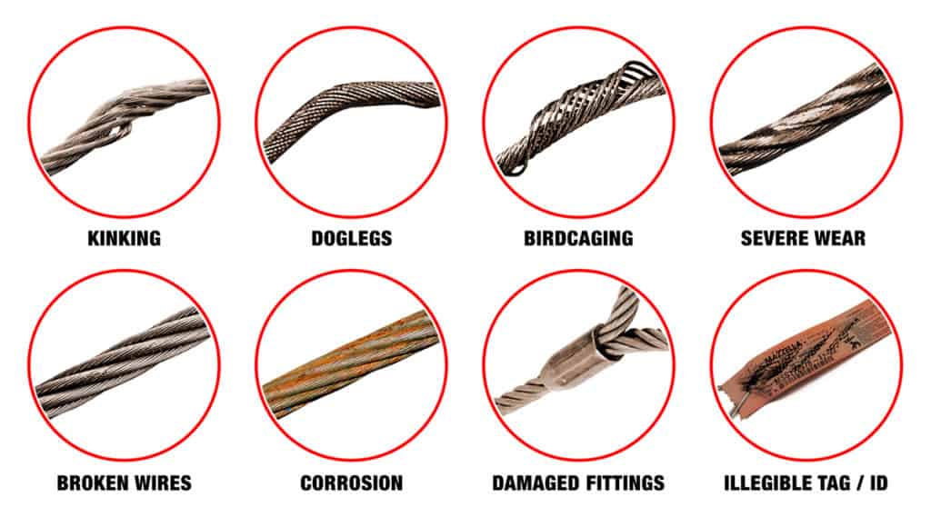
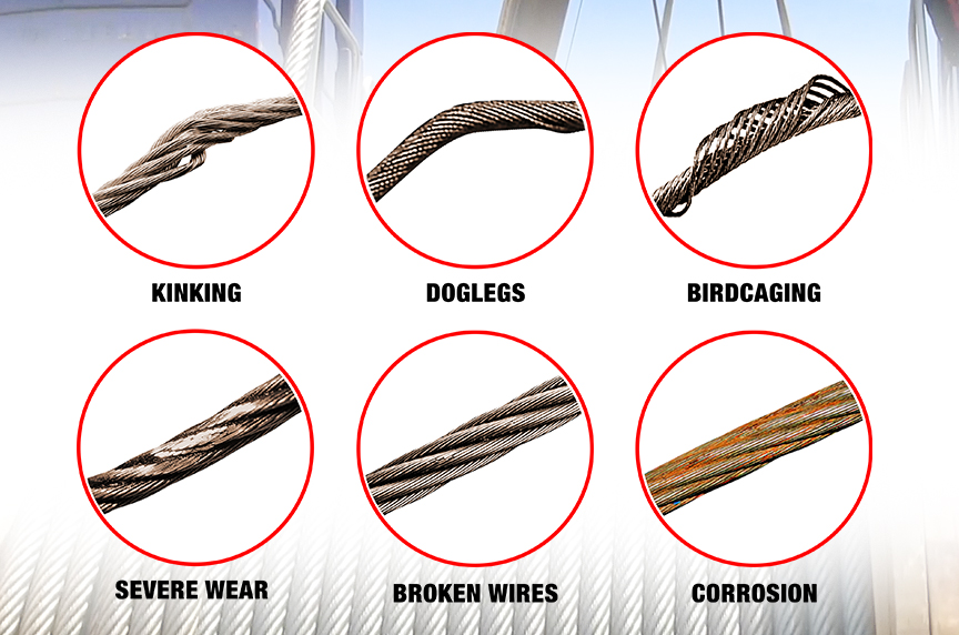
Distortion: Kinking, crushing, birdcaging, or other damage which distorts the rope structure. The main thing to look for are wires or strands that are pushed out of their original position in the rope. Slight bends in a rope where wires or strands are relatively in their original position would not be considered serious damage. But good judgment is indicated.
Corrosion: Severe corrosion of the rope or end attachments which has caused pitting or binding of wires should be cause for replacement. Light rusting usually does not affect the strength of a sling.
Mechanical Damages: One of the most common causes of damage is the kink which results from pulling the sling body through the loop (choker hitching), thus causing wires or strands to be deformed and pushed out of their original position. This unbalances the sling, reducing its strength.
Disposition: The best inspection program available is of no value if slings, which are worn out and have been retired, are not disposed of properly. Retired slings should be tagged DO NOT USE to prevent any further usage. The sling should be destroyed as soon as possible by cutting the eye and fittings from the rope.
Inspect the bearing point of the eye. Check for deformation and wear of sleeve, thimbles, and all attached hardware. Check for broken wires where the rope enters the sleeve or socket.
Both ASTM B.30.9 and most Provincial Regulations require that wire rope slings receive two types of inspections: a PRIOR TO USE visual inspection, and additional inspections where severe conditions warrant.
Daily inspections are intended to detect serious damage or deterioration which would weaken the sling. Look for obvious things, such as broken wires, kinks, crushing, broken attachments, severe corrosion.
Additional inspections must be carried out by a designated person who must have good knowledge of wire rope. The frequency of these regular inspections should be based on:

A competent person must begin a visual inspection prior to each shift the equipment is used, which must be completed before or during that shift. The inspection must consist of observation of wire ropes (running and standing) that are likely to be in use during the shift for apparent deficiencies, including those listed in paragraph (a)(2) of this section. Untwisting (opening) of wire rope or booming down is not required as part of this inspection.
Significant distortion of the wire rope structure such as kinking, crushing, unstranding, birdcaging, signs of core failure or steel core protrusion between the outer strands.
In running wire ropes: Six randomly distributed broken wires in one rope lay or three broken wires in one strand in one rope lay, where a rope lay is the length along the rope in which one strand makes a complete revolution around the rope.
In rotation resistant ropes: Two randomly distributed broken wires in six rope diameters or four randomly distributed broken wires in 30 rope diameters.
In pendants or standing wire ropes: More than two broken wires in one rope lay located in rope beyond end connections and/or more than one broken wire in a rope lay located at an end connection.
If a deficiency in Category I (see paragraph (a)(2)(i) of this section) is identified, an immediate determination must be made by the competent person as to whether the deficiency constitutes a safety hazard. If the deficiency is determined to constitute a safety hazard, operations involving use of the wire rope in question must be prohibited until:
If the deficiency is localized, the problem is corrected by severing the wire rope in two; the undamaged portion may continue to be used. Joining lengths of wire rope by splicing is prohibited. If a rope is shortened under this paragraph, the employer must ensure that the drum will still have two wraps of wire when the load and/or boom is in its lowest position.
If a deficiency in Category II (see paragraph (a)(2)(ii) of this section) is identified, operations involving use of the wire rope in question must be prohibited until:
The employer complies with the wire rope manufacturer"s established criterion for removal from service or a different criterion that the wire rope manufacturer has approved in writing for that specific wire rope (see § 1926.1417),
If the deficiency is localized, the problem is corrected by severing the wire rope in two; the undamaged portion may continue to be used. Joining lengths of wire rope by splicing is prohibited. If a rope is shortened under this paragraph, the employer must ensure that the drum will still have two wraps of wire when the load and/or boom is in its lowest position.
If the deficiency (other than power line contact) is localized, the problem is corrected by severing the wire rope in two; the undamaged portion may continue to be used. Joining lengths of wire rope by splicing is prohibited. Repair of wire rope that contacted an energized power line is also prohibited. If a rope is shortened under this paragraph, the employer must ensure that the drum will still have two wraps of wire when the load and/or boom is in its lowest position.
Where a wire rope is required to be removed from service under this section, either the equipment (as a whole) or the hoist with that wire rope must be tagged-out, in accordance with § 1926.1417(f)(1), until the wire rope is repaired or replaced.
The inspection must include any deficiencies that the qualified person who conducts the annual inspection determines under paragraph (c)(3)(ii) of this section must be monitored.
Wire ropes on equipment must not be used until an inspection under this paragraph demonstrates that no corrective action under paragraph (a)(4) of this section is required.
At least every 12 months, wire ropes in use on equipment must be inspected by a qualified person in accordance with paragraph (a) of this section (shift inspection).
The inspection must be complete and thorough, covering the surface of the entire length of the wire ropes, with particular attention given to all of the following:
Exception: In the event an inspection under paragraph (c)(2) of this section is not feasible due to existing set-up and configuration of the equipment (such as where an assist crane is needed) or due to site conditions (such as a dense urban setting), such inspections must be conducted as soon as it becomes feasible, but no longer than an additional 6 months for running ropes and, for standing ropes, at the time of disassembly.
If the deficiency is localized, the problem is corrected by severing the wire rope in two; the undamaged portion may continue to be used. Joining lengths of wire rope by splicing is prohibited. If a rope is shortened under this paragraph, the employer must ensure that the drum will still have two wraps of wire when the load and/or boom is in its lowest position.
If the qualified person determines that, though not presently a safety hazard, the deficiency needs to be monitored, the employer must ensure that the deficiency is checked in the monthly inspections.
All documents produced under this section must be available, during the applicable document retention period, to all persons who conduct inspections under this section.
Government regulations are specific on when to inspect. Both ASME Standard B30.9 and OSHA require that wire rope slings receive two types of inspections: a daily visual inspection, and additional inspections where service conditions warrant.
Daily visual inspections are intended to detect serious damage or deterioration which would weaken the sling. This inspection is usually performed by the person using the sling in a day-to-day job. The user should look for obvious things, such as broken wires, kinks, crushing, broken attachments, severe corrosion, etc.
Additional inspections should be performed at regular intervals based on, (1) frequency of sling use, (2) severity of service conditions. (3) nature of lifts and (4) prior experience based on service life of slings used in similar circumstances.
It is required that these additional inspections be carried out by a designated person who must have good knowledge of wire rope. An accurately written and dated record of all conditions observed shall be maintained. Any deterioration of the sling which could result in appreciable loss of original strength should be carefully noted and determination made on whether further use would constitute a safety hazard.
When an eye is formed in a sling, the rope is formed into a relatively sharp bend to form the eye. This bend increases the clearance between the strands on the outside of the eye and, in some cases, this clearance accumulates between two strands. This is not a reason for concern in a new sling, and the sling is acceptable for use.
During the initial and subsequent loadings, this clearance between strands, and position of the strands in the eye of the sling, may change. The condition of all slings must be evaluated in accordance with ASME B30.9, or other applicable standards or regulations, in order to determine the suitability for continued use.
Precisely how to make proper, adequate inspections is not detailed by OSHA—yet it is in the knowledge of the inspector that the big difference between a good inspection and something less becomes apparent.
Inspection should follow a systematic procedure:First, it is necessary that all parts of the sling are readily visible. The sling should be laid out so every part is accessible.
Next, the sling should be sufficiently cleaned of dirt and grease so wires and fittings are easily seen. This can usually be accomplished with a wire brush or rags.
A knowledgeable inspector will also insist on proper storage for out-of-use slings—to make his job easier, if not for the good of the slings. Inspections are much easier—and probably more thorough—when slings are available for inspection in an orderly arrangement, out of the weather and away from heat and dirt.
Like any other machine, wire rope is thoroughly lubricated at time of manufacture. Normally, for sling use under ordinary conditions, no additional lubrication is required. However, if a sling is stored outside or in an environment which would cause corrosion, lubrication should be applied during the service life to prevent rusting or corroding.
The following is a fairly comprehensive listing of critical inspection factors. It is not, however, presented as a substitute for an experienced inspector. It is rather a user’s guide to the accepted standards by which wire ropes must be judged. Use the outline to skip to specific sections:
Rope abrades when it moves through an abrasive medium or over drums and sheaves. Most standards require that rope is to be removed if the outer wire wear exceeds 1/3 of the original outer wire diameter. This is not easy to determine, and discovery relies upon the experience gained by the inspector in measuring wire diameters of discarded ropes.
All ropes will stretch when loads are initially applied. As a rope degrades from wear, fatigue, etc. (excluding accidental damage), continued application of a load of constant magnitude will produce incorrect varying amounts of rope stretch.
Initial stretch, during the early (beginning) period of rope service, caused by the rope adjustments to operating conditions (constructional stretch).
Following break-in, there is a long period—the greatest part of the rope’s service life—during which a slight increase in stretch takes place over an extended time. This results from normal wear, fatigue, etc.
Thereafter, the stretch occurs at a quicker rate. This means that the rope has reached the point of rapid degradation: a result of prolonged subjection to abrasive wear, fatigue, etc. This second upturn of the curve is a warning indicating that the rope should soon be removed.
In the past, whether or not a rope was allowed to remain in service depended to a great extent on the rope’s diameter at the time of inspection. Currently, this practice has undergone significant modification.
Previously, a decrease in the rope’s diameter was compared with published standards of minimum diameters. The amount of change in diameter is, of course, useful in assessing a rope’s condition. But, comparing this figure with a fixed set of values can be misleading.
As a matter of fact, all ropes will show a significant reduction in diameter when a load is applied. Therefore, a rope manufactured close to its nominal size may, when it is subjected to loading, be reduced to a smaller diameter than that stipulated in the minimum diameter table. Yet under these circumstances, the rope would be declared unsafe although it may, in actuality, be safe.
As an example of the possible error at the other extreme, we can take the case of a rope manufactured near the upper limits of allowable size. If the diameter has reached a reduction to nominal or slightly below that, the tables would show this rope to be safe. But it should, perhaps, be removed.
Today, evaluations of the rope diameter are first predicated on a comparison of the original diameter—when new and subjected to a known load—with the current reading under like circumstances. Periodically, throughout the life of the rope, the actual diameter should be recorded when the rope is under equivalent loading and in the same operating section. This procedure, if followed carefully, reveals a common rope characteristic: after an initial reduction, the diameter soon stabilizes. Later, there will be a continuous, albeit small, decrease in diameter throughout its life.
Deciding whether or not a rope is safe is not always a simple matter. A number of different but interrelated conditions must be evaluated. It would be dangerously unwise for an inspector to declare a rope safe for continued service simply because its diameter had not reached the minimum arbitrarily established in a table if, at the same time, other observations lead to an opposite conclusion.
Corrosion, while difficult to evaluate, is a more serious cause of degradation than abrasion. Usually, it signifies a lack of lubrication. Corrosion will often occur internally before there is any visible external evidence on the rope surface.
Pitting of wires is a cause for immediate rope removal. Not only does it attack the metal wires, but it also prevents the rope’s component parts from moving smoothly as it is flexed. Usually, a slight discoloration because of rusting merely indicates a need for lubrication.
Severe rusting, on the other hand, leads to premature fatigue failures in the wires necessitating the rope’s immediate removal from service. When a rope shows more than one wire failure adjacent to a terminal fitting, it should be removed immediately. To retard corrosive deterioration, the rope should be kept well lubricated with a clear wire rope lube that can penetrate between strands. In situations where extreme corrosive action can occur, it may be necessary to use galvanized wire rope.
Kinks are tightened loops with permanent strand distortion that result from improper handling when a rope is being installed or while in service. A kink happens when a loop is permitted to form and then is pulled down tight, causing permanent distortion of the strands. The damage is irreparable and the sling must be taken out of service.
Doglegs are permanent bends caused by improper use or handling. If the dogleg is severe, the sling must be removed from service. If the dogleg is minor, exhibiting no strand distortion and cannot be observed when the sling is under tension, the area of the minor dogleg should be marked for observation and the sling can remain in service.
Bird caging results from torsional imbalance that comes about because of mistreatment, such as sudden stops, the rope being pulled through tight sheaves, or wound on too small a drum. This is cause for rope replacement unless the affected section can be removed.
Particular attention must be paid to wear at the equalizing sheaves. During normal operations, this wear is not visible. Excessive vibration or whip can cause abrasion and/or fatigue. Drum cross-over and flange point areas must be carefully evaluated. All end fittings, including splices, should be examined for worn or broken wires, loose or damaged strands, cracked fittings, worn or distorted thimbles and tucks of strands.
After a fire or the presence of elevated temperatures, there may be metal discoloration or an apparent loss of internal lubrication. Fiber core ropes are particularly vulnerable. Under these circumstances the rope should be replaced.
Continuous pounding is one of the causes of peening. This can happen when the rope strikes against an object, such as some structural part of the machine, or it beats against a roller or it hits itself. Often, this can be avoided by placing protectors between the rope and the object it is striking.
Another common cause of peening is continuous working-under high loads—over a sheave or drum. Where peening action cannot be controlled, it is necessary to have more frequent inspections and to be ready for earlier rope replacement.
Below are plain views and cross-sections show effects of abrasion and peening on wire rope. Note that a crack has formed as a result of heavy peening.
Scrubbing refers to the displacement of wires and strands as a result of rubbing against itself or another object. This, in turn, causes wear and displacement of wires and strands along one side of the rope. Corrective measures should be taken as soon as this condition is observed.
Wires that break with square ends and show little surface wear have usually failed as a result of fatigue. Such fractures can occur on the crown of the strands or in the valleys between the strands where adjacent strand contact exists. In almost all cases, these failures are related to bending stresses or vibration.
If diameter of the sheaves, rollers or drum cannot be increased, a more flexible rope should be used. But, if the rope in use is already of maximum flexibility, the only remaining course that will help prolong its service life is to move the rope through the system by cutting off the dead end. By moving the rope through the system, the fatigued sections are moved to less fatiguing areas of the reeving.
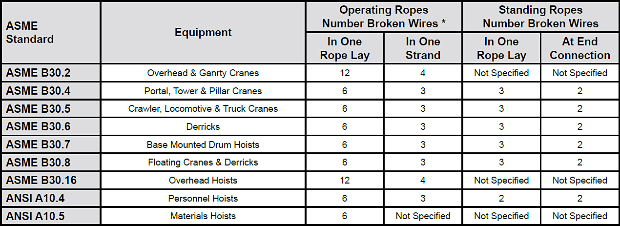
The number of broken wires on the outside of a wire rope are an index of its general condition, and whether or not it must be considered for replacement. Frequent inspection will help determine the elapsed time between breaks. Ropes should be replaced as soon as the wire breakage reaches the numbers given in the chart below. Such action must be taken without regard to the type of fracture.
* All ropes in the above applications—one outer wire broken at the point of contact with the core that has worked its way out of the rope structure and protrudes or loops out of the rope structure. Additional inspection of this section is required.
Rope that has either been in contact with a live power line or been used as “ground” in an electric welding circuit, will have wires that are fused, discolored and/or annealed and must be removed.
On occasion, a single wire will break shortly after installation. However, if no other wires break at that time, there is no need for concern. On the other hand, should more wires break, the cause should be carefully investigated.
On any application, valley breaks—where the wire fractures between strands—should be given serious attention. When two or more such fractures are found, the rope should be replaced immediately. (Note, however, that no valley breaks are permitted in elevator ropes.)
It is good to remember that once broken wires appear—in a rope operating under normal conditions—a good many more will show up within a relatively short period. Attempting to squeeze the last measure of service from a rope beyond the allowable number of broken wires (refer to table on the next page) will create an intolerably hazardous situation.
Recommended retirement criteria for all Rotation Resistant Ropes are 2 broken wires in 6 rope diameters or 4 broken wires in 30 rope diameters (i.e. 6 rope diameters for a 1″ diameter rope = 6″).
Distortion of Rotation Resistant Ropes, as shown below, can be caused by shock load / sudden load release and/or induced torque, and is the reason for immediate removal from service.
NDT Technology, LLC. is a developer and manufacturer of nondestructive test instrumentation for the in-service inspection of wire ropes and cables. Our company is the world’s premier maker of wire rope inspection instrumentation. Our success in this niche business can be attributed to the superior performance of our products and our never-ending pursuit of innovation.
Our wire rope NDE equipment is especially suited for the inspection of so-called high-value wire ropes (i.e., large diameter (>100mm) subsea construction ropes with lengths in excess of 2000m). Our rope testers also show great promise for the inspection of spiral strand.
In addition to guidance on storage, handling, installation and maintenance, this document provides discard criteria for those running ropes which are subjected to multi-layer spooling, where both field experience and testing demonstrate that deterioration is significantly greater at the crossover zones on the drum than at any other section of rope in the system.
It also provides more realistic discard criteria covering decreases in rope diameter and corrosion, and gives a method for assessing the combined effect of deterioration at any position in the rope.
ISO 4309:2017 applies to rope on cranes, winches and hoists used for hook, grabbing, magnet, ladle, excavator or stacking duties, whether operated manually, electrically or hydraulically.
NOTE In view of the fact that the exclusive use of synthetic sheaves or metal sheaves incorporating synthetic linings is not recommended when single-layer spooling at the drum, due to the inevitability of wire breaks occurring internally in large numbers before there is any visible evidence of any wire breaks or signs of substantial wear on the periphery of the rope, no discard criteria are given for this combination.

Test data are represented usually on strip-chart record or on 2D printed traces of signal by steel rope NDT. Most of present magnetic steel rope flaw detectors work as two-functional (two-channel) instruments: one channel for loss of metallic area (LMA) measurement of a rope and another for local faults (LF) detection. Record of the LMA channel represents LMA value in percents relative to a standard value of rope metallic area as a function of distance along the rope. The LF channel records sensor signals that appear due to LF like broken wires, local corrosion etc. along rope under test. A path signal generator used to get distance marks on the records.
Rejection criteria for ropes in use take into consideration limitations in LMA and LF as like as rope dimensions change and disturbance of rope structure.
Earlier rope flaw detectors used chart recording as base method of test data representation. Of course, chart record contains the most full information about rope condition. The information must be interpreted correctly to identify possible faults of a rope. Therefore inspectors must be skilful and experienced. Besides it takes much time because of usual big length of a record. Nevertheless, errors are inevitable since interpretation and identification processes are subjective. Another disadvantage of chart recorder use is fixed amplitude and distance scaling. Therefore it is difficult to interpret signal traces with wide range of signal magnitude, e.g. corresponding to location of rope metallic core broken or to place of rope splicing. One more disadvantage is the problem of interpretation when rope speed changes.
Inspection procedure by flaw detectors depends on purpose of a rope use and its positioning in equipment or construction. Thus, inspection procedures for mine hoist rope, for elevator rope and for stay rope (guy) are different. In particular, demand to minimize inspection time is actual when ropes of mine hoist or hot-metal crane are checked. Often it is necessary to get inspection data in real time to stop rope move and to inspect the rope section visually just after significant LF or LMA signals appear.
Another procedure is used to test guys. In this case a magnetic head of flaw detector moves along rope under test. Test data are transferred to an electronic unit by a cable and then are recorded or/and are loaded down to computer for processing.
The real time data recording procedure demands to perform it by high skilled expert who can quickly interpret a record. Of course, the inspection result is subjective.
Documentation of testing result is important part of inspection. There are requirements for testing report in rules and instructions of many countries. According to these rules the report must include information of a rope under test (construction, dimensions, location, use etc.), of a flaw detector used and of its adjustment, of testing procedure, of inspection personnel. The more important part of the report is signal traces of LMA and LF channels.
The steel rope magnetic flaw detector INTROS designed and manufactured by INTRON PLUS, Ltd. can be applied for inspection using both the procedures mentioned. It consists of a universal electronic unit and different magnetic heads (Fig.1) to test ropes of various constructions and dimensions [1]. The microprocessor electronic unit is portable (not more than 0.8 kg) and is used as data logger with memory sufficient to save testing data of (2-12) km of rope in the LMA and LF channels simultaneously. The unit can be used as in-situ interpreter of test results for real-time inspection using its own LCD display, light and sound alarm. A chart recorder can be connected to the INTROS electronic unit. Recording is possible as in real time (in-situ) simultaneously with data downloading to the unit storage so after testing by the data transfer from the storage. The scales of the record are set automatically during instrument calibration.
Due to portability and self-contained power supplying the electronic unit can be fixed at magnetic head to work as full independent instrument moving along rope under test far away from inspector. This is useful by guy of bridges or buildings inspection.
The software WINTROS is intended for test data processing after they are downloaded into a computer. The WINTROS provided many of functions: different kinds of filtering, noise cutting-off, zero level displacing, rejecting and alarm levels setting, amplitude and distance scaling (zooming), auto-scaling, signal traces "lacing", aligning of some signal traces by distance and others. The last function is very helpful to follow rope condition within its lifetime. It is important to catch a moment when rope wearing speed increases significantly. In this case time intervals between inspections must be decreased.
Test data accumulation in electronic format allows to create databases for many ropes under test and to exchange data by modern communication means, e.g. by e-mail.
The inspection report as a final document is filed and printed after test data processing (Fig.2). It consists of two parts: text one and graphical one. The graphical part includes diagrams representing compressed information about LMA (left) and LF (right). Height of the bar on the LF diagram represents the relative magnitude of the largest LF signals. Distance of the rope sections correlated to the signals is shown below. Two horizontal lines on the LMA diagram show the rejection (upper) and the alarm (under) levels of rope LMA.
The diagrams may be used as a basis for conclusion about a rope under test condition and its further use without detail analysis of signal traces. The traces are attached to the report in two versions: one is original and another is after processing fulfilled by an expert. Thus, the inspection report is an exhaustive document for the expert conclusion.
The INTROS instrument has being used for rope inspection at various equipment and installations in Russia, Ukraine and Kazakhstan for years and since 1998 - in Germany. Some examples of interpretation of test data are cited below.
Fig.3 and Fig.4 shows LMA and LF signal traces before and after processing by the WINTROS. The LMA traces (Fig.4) are low-pass filtered and the LF traces (Fig.4) are filtered by an optimal filter and cut-off. Fig.4 consists of two traces got with 10-weeks interval for the same rope. All the traces relate to inspection of 30.5mm diameter brake rope at the cargo/man-riding two-deck cage of the "Scalistaja" shaft of "Norilsky nickel" mining enterprise. The traces show that the most worn section is located at the distance of (800-1100) m from the ground surface. LMA increased here from 6.5% to 8.8% within 10 weeks. There is significant corrosion damage of the section too as it can be seen at the LF traces. That is why inspector ordered to test the rope monthly and when LMA attained 10% then the rope was removed. Investigation confirmed the INTROS testing data.
Fig.5 illustrates the INTROS signal traces of rope inspection of the hot-metal overhead travelling crane at "Severstal" steel plant. The LMA traces recorded with 1-week interval show 6 most worn sections concentrated in the rope part nearest to a hot-metal ladle. There are 3 high LMA peaks and 3 lower ones between them. It appears during investigation of the traces that the first 3 peaks relate to the rope sections, which are located on hoisting blocks (approached to the ladle for 3m) when the ladle is loaded or unloaded by hot metal. The sections are exposed by dynamic load and high temperature simultaneously. Therefore the rope sections wires are damaged mechanically and are lost strength due to metal structure change. The change influences on the INTROS output due to wire metal magnetic condition change.
The lower 3 peaks correlate to tackle blocks of the crane, which are located at least in about 15m from the ladle and are not exposed by high temperature. There is only mechanical damage of wires here, without structural change.
The DMT TesTec Division (earlier WBK-Rope-Testing-Institute) has long experience with the inspection of steel ropes for more than 100 years. For many years steel ropes used in coal mines have been inspecting by the company. Today the company is involved in inspection of wider range of ropes: ropes for the potash and salt mines, crane ropes, bridge ropes and guy ropes of broadcast towers, etc.
The magneto-inductive devices used for these purposes utilize sensor coils. Four differential coils, which enclosed the rope as half-coils in two planes, detect the stray fields (4 LF signals). Usage of 4 coils system and special location of that coils makes possible detection of broken wires. The magnetic flux is determined by a measuring coil that encloses the rope. The magnitude of the magnetic flux is proportional to the meaning of metallic cross-section of the rope (LMA signal).
The electronic device RTI has a chart recorder integrated, which presents the rope charts during test. Test data are stored into a PCMCIA-Memory card for further evaluation. Special software developed for test data evaluation is able to determine the maximum of wire breaks per reference length along the rope and determine the section with maximum loss of metallic area along the rope. Both the maximum wire breaks per reference length (caused by fatigue fractures) and the maximum loss of metallic area (caused corrosion and wear) are decisive criteria for the determination of the point of discarding or the specification of inspection cycles for ropes.
The use of coils causes a more extensive electronics as well as an increased handling of the system. Therefore the ranges of application of the rope test instrument INTROS based on Hall-sensors where checked since 1998. A good agreement of the results at the determination of the metallic cross section was observed between both rope test instruments. The RTI device shows clearly more distinctive amplitudes at the recognition of wire breaks. The wire break signals where however also recognized at the INTROS device with the help of the LMA trace. The software developed for the RTI device was brought into line for the INTROS device.
An example for the determination of the loss of metallic area during the life time is represented in Fig. 6. These results are obtained from Koepe hoist shaft of the main haulage plant of the DSK (German hard coal industry). The conditions in the shaft are very damp and the ropes reached their point of discarding because of corrosion and wear. The area of the maximum damage is within the acceleration section for these hoisting ropes.

Wire rope lifting slings, bridles and assemblies provide great durability and high tensile strength for lifting heavy loads. In addition, wire rope lifting slings are lighter in weight and more cost efficient than chain slings. Wire rope slings, sometimes referred to as wire slings, or cable lifting slings, are constructed using a variety of different styles and sizes of steel wire rope. Every style and size of wire rope offers different properties and benefits such as:
Each type of wire rope has benefits and drawbacks. What all wire ropes have in common however, is that they are made up of steel wires which form individual stands. These strands are laid in a helical pattern around a fiber or steel IWRC (independent wire rope core) core.
Wire rope lifting slings, bridles and assemblies are highly customizable, so if you are unable to find what you are looking for, or if you don’t know exactly what you need, call or email our sales team to speak with a rigging product specialist.
The durability of steel cable lifting slings is also put to the test in the harsh environments seen in steel mills and forging facilities. Every steel wire rope configuration will offer different properties and will be better equipped to handle certain applications. Generally, a smaller number of large outer wires will provide more wear, corrosion and abrasion resistance. Conversely, a larger number of smaller outer wires will provide better flexibility and fatigue resistance.
After you decide what construction and size of wire rope fits your application, you must configure the entire sling. Wire rope bridles and assemblies are available in single-leg, double-leg, triple-leg, and quadruple-leg configurations. They most commonly have 2 eyes and are constructed using a mechanical flemish splice. Wire rope lifting slings can be used in vertical, choker and basket hitches. They can also be equipped with a variety of attachments and fittings to accommodate almost any overhead lifting application.
Although wire rope sling fittings and attachment can be reused, the wire rope itself is not repairable. If a wire rope sling fails an inspection, it is to be properly destroyed and disposed of
It is important to inspect wire rope slings regularly and to keep a record of all sling inspections. At Tri-State Rigging Equipment we offer a full range of rigging inspection and repair services. The standards that govern wire rope sling inspection are OSHA 1910.184 and ASME B30.9. It is recommended that wire rope rigging slings first undergo an initial inspection when you receive the lifting sling from the manufacturer. The purpose of this initial inspection is to:
Wire rope slings, bridles and assemblies should also be inspected by a designated and qualified individual every day before use to make sure that the sling is in working condition and will lift its rated capacity. The person performing the inspection should examine all the wire rope, fastenings and attachments on the wire rope sling. The inspector is looking for visual indications of any defects, deformities and general damage that might affect the integrity of the sling.
Depending on your application, it may be recommended that you perform these visual inspections more than once a day. If the wire rope sling is used many times throughout the day, by multiple individuals, across multiple shifts, it is imperative that the sling be inspected before every shift change and before any change in lifting application.
ASME standards further require a thorough periodic inspection to be performed at least once a year by either a professional service provider, or by a Qualified Person. In addition, written records must be kept until the next periodic inspection. The rejection criteria for periodic wire rope sling inspections are as follows:
10 or more randomly distributed broken wires in one rope lay, or 5 or more broken wires in one strand in one rope lay, for strand-laid grommets and single part slings.
If your wire rope sling shows any of the rejection criteria above, you must remove the sling from service, and it must be destroyed. Properly destroying rigging equipment is imperative because you can be held accountable for damage done by people who find and use your discarded slings. Therefore, lifting slings deemed not suitable for service must be destroyed beyond use and beyond repair. The process for destroying a wire rope sling is as follows:
The purpose of daily and periodic wire rope sling inspections is not to get anyone in trouble but rather to gain knowledge of the frequency of use, severity of conditions, and nature of lifts, and consider how all these factors affect your wire rope sling. The most important reason to perform daily and periodic wire rope sling inspections, however, is to keep you and your coworkers safe.
Tri-State Rigging Equipment is a custom manufacturer, service provider and distributor for all wire rope lifting slings serving clients from coast to coast, Canada, Mexico and especially focused in the states of Missouri, Illinois, Indiana, Iowa, Kansas, Nebraska, Arkansas, Mississippi, Tennessee, Kentucky, South Carolina, Florida, and Oklahoma.


 8613371530291