
wire rope installation guide quotation

Marine Eye Fitting Size Select Marine Eye Fittings IDTMI# 360-003 wire with diameters .190, .218, .093, 1.572wire with diameters .190, .254, .108, 1.945TMI# 360-003.2 wire with diameters .190, .383.195, 2.352wire with diameters .250, .406, .202, 2.655wire with diameters .313, .543, .260, 3.071TMI# 360-003 wire with diameters .190, .218, .093, 1.572wire with diameters .190, .254, .108, 1.945TMI# 360-003.2 wire with diameters .190, .383.195, 2.352wire with diameters .250, .406, .202, 2.655wire with diameters .313, .543, .260, 3.071
Wire rope is shipped in cut lengths, either in coils or on reels. Great care should be taken when the rope is removed from the shipping package since it can be permanently damaged by improper unreeling or uncoiling. Looping the rope over the head of the reel or pulling the rope off a coil while it is lying on the ground, will create loops in the line. Pulling on a loop will, at the very least, produce an imbalance in the rope and may result in open or closed kinks (Fig. 18). Once a rope is kinked, the damage is not repairable. The kink must be cut out or the rope is unfit for service.
Figure 18.Improper handling can create open (a) or, closed kinks b). The open kink will open the rope lay: the closed kink will close it. Starting loop (c): Do not allow the rope to form a loop. If. however, a loop does form and is removed at the stage show. a kink can be avoided. Kink (d): In this case. the looped rope was put under tension, the kink was formed. the rope is permanently damaged.
There are three methods to perform this step correctly:The reel is mounted on a shaft supported by two jacks or a roller payoff (Fig.19). Since the reel is free to rotate, the rope is pulled from the reel by a workman holding the rope end, and walking away from the reel as it unwinds. A braking device should be employed so that the rope is kept taut and the reel is restrained from over-running the rope. This is necessary particularly with powered de-reeling equipment.
Another method involves mounting the reel on an unreeling stand (Fig. 20). It is then unwound in the same manner as described above (1). In this case, however, greater care must be exercised to keep the rope under tension sufficient to prevent the accumulation of slack. Slack can allow the rope to drop below the lower reel head and be damaged or loose wraps on the reel to fall
In another accepted method, the end of the rope is held while the reel itself is rolled along the ground. With this procedure, the rope will payoff properly however, the end being held will travel in the direction the reel is being rolled. As the difference between the diameter of the reel head and the diameter of the wound rope increases, the speed of travel will increase.
Figure 19. The wire rope reel is mounted on a shaft supported by jacks. This permits the reel to rotate freely. and the rope can be unwound either manually or by a powered mechanism.
When re-reeling wire rope from a horizontally supported reel to a drum it is preferable for the rope to travel from the top of the reel to the top of the drum; or, from the bottom of the reel to the bottom of the drum (Fig. 21). Re-reeling in this manner will avoid putting a reverse bend into the rope during installation. If a rope is installed so that a reverse bend is induced, it may cause the rope to become "twisty" and, consequently, harder to handle. When unwinding wire rope from a coil, there are two suggested methods for carrying out this procedure in a proper manner:
1) One method involves placing the coil on a vertical unreeling stand. The stand consists of a base with a fixed vertical shaft. On this shaft there is a "swift," consisting of a plate with inclined pins positioned so that the coil may be placed over them. The whole swift and coil then rotate as the rope is pulled off. This method is particularly effective when the rope is to be wound on a drum.
2) The most common as well as the easiest uncoiling method is merely to hold one end of the rope while rolling the coil along the ground like a hoop (Fig. 22). Figures 23 and 24 show unreeling and uncoiling methods that are most likely to cause kinks. Such improper procedures must be avoided in order to prevent the occurrence of loops. These loops, when pulled taut, will inevitably result in kinks. No matter how a kink develops, it will damage strands and wires, and the kinked section must be cut out. Proper and careful handling will keep the wire rope free from kinks.
Drums are the means y which power is transmitted to the rope and then to the object to be moved. For the wire rope to pick up this power efficiently and to transmit it properly to the working end, the installation must be carefully controlled. If the drum is grooved, the winding conditions should be closely supervised to assure adherence to the following recommended procedures:
I) The end of the rope must be secured to the drum by such means as will give the end termination at least as much strength as is specified by the equipment manufacturer.
2) Adequate tension must be maintained on the rope while it is being wound so that the winding proceeds under continuous tension. Back tension applied to the rope during installation" should be from 2 to 5% of the minimum breaking force of the rope being installed.
4) It is preferable to have at least three dead wraps remaining on the drum when the rope is unwound during normal operation. Two dead wraps are a mandatory requirement in many codes and standards. If the wire rope is carelessly wound and, as a result, jumps the grooves, it will be crushed and cut where it crosses from one groove to the other. Another, almost unavoidable problem is created at the drum flange; as the rope climbs to a second layer there is further crushing and the wires receive excessive abrasion.
drum grooves relative to the actual rope diameter. Wire rope is normally manufactured to a plus tolerance. (See Table 3.) The oversize tolerance of the rope must be taken into account or the rope will be damaged by poor spooling caused
inches. Yet, by Federal standards, a 1/4-inch rope may have a diameter as large as .265 inches. If a rope of this size were to be operated on a drum with a .250 inch pitch, crowding would occur and the rope would be forced out of the groove.
Installation of a wire rope on a plain (smooth) face drum requires a great deal of care. The starting position should be at the correct drum flange so that each wrap of the rope will wind tightly against the preceding wrap (Fig. 32). Here too, close supervision should be maintained during installation. This will help make certain that:
2 ) Appropriate tension on the rope is maintained as it is wound on the drum. Back tension applied to the rope during installation should be from 2 to 5% of the minimum breaking force of the rope being installed.
4) It is preferable to have at least three dead wraps remaining on the drum when the rope is unwound during normal operation. Two dead wraps are a mandatory requirement in many codes and standards. Loose and uneven winding on a plain (smooth) faced drum can and usually does create excessive wear, crushing and distortion of the rope. The results of such abuse are shorter service life and a reduction in the rope"s effective strength. Also, for an operation that is sensitive in terms of moving and spotting a load, the operator will encounter control difficulties as the rope will pile up, pull into the pile and fall from the pile to the drum surface. The ensuing shock can break or otherwise damage the rope.
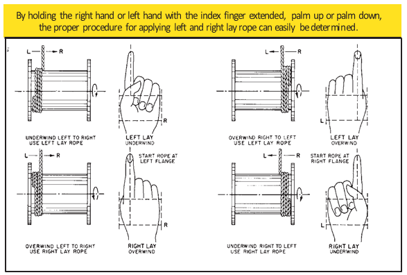
Figure 32. By holding the right or left hand with index finger extended, palm up or palm down, the proper procedure for applying left-and right-lay rope on a smooth drum can be easily determined.
The proper direction of winding the first layer on a smooth drum can be determined by standing behind the drum and looking along the path the rope travels, and then following one of the procedures illustrated in Figure 32. The diagrams show: the correct relationship that should be maintained between the direction of lay of the rope (right or left), the direction of rotation of the drum (overwind or underwind) and winding from left to right or right to left. Order Wire Rope & Cable
Many installations are designed with requirements for winding more than one layer of wire rope on a drum. Winding multiple layers presents some further problems.The first layer should wind in a smooth, tight helix which, if the drum is grooved,
is already established. The grooves allow the operator to work off the face of the drum, and permit the minimum number of dead wraps. A smooth drum present" an additional problem, initially, as the wire rope must be wound in such a manner that the first layer will be smooth and uniform and will provide a firm foundation for the layers of rope that will be wound over it. The first layer of rope on the smooth drum should be wound with tension (2 to 5% of the minimum breaking force of the rope) sufficient to assure a close helix - each wrap being wound as close as possible to the preceding wrap. The first layer then acts as a groove which will guide the successive layers. Unlike wire ropes operating on grooved drums, the first layer should not be unwound from a smooth-faced drum with multiple layers. After the rope has wound completely across the face of the drum (either smooth or grooved), it is forced up to a second layer at the flange. The rope then winds back across the drum in the opposite direction, lying in the valleys between the wraps of the rope on the first layer. Advancing across the drum on the second layer, the rope, following the "grooves" formed by the rope on the first layer, actually winds back one wrap in each revolution of the drum. The rope must then cross one or two rope "grooves" (depending upon the type of grooving - single or double cross-over) in order to advance across the drum for each turn. The point at which this occurs is known as the cross-over. Cross-over is unavoidable on the second, and all succeeding layers. Figure 33 illustrates the winding of a rope on the second layer from left to right, and from right to left-the direction is shown by the arrows.
At these cross-over points, the rope is subjected to severe abrasion and crushing as it is pushed over the "grooves" and rides across the crown of the first rope layer. The scrubbing of the rope, as this is happening, can easily be heard.
Helical grooving does not employ a built in cross-over and does not work as well for multiple layers spooling as a counterbalanced drum because it does not have the cross-over and does not consistently put the rope in the proper position at the
Counterbalance grooving with two cross-overs is made so that each wrap of rope winds parallel to the drum flange for a distance less than half the circumference around the drum, then follows a short cross-over to complete half the drum circumference. The cross-over is at an angle with the drum flange and displaces the rope laterally by half the pitch of grooving.
The grooving for this type of winding is similar to the parallel grooving except that half the drum circumference is laterally displaced from the other half by half the pitch of grooving, and between these two halves the grooves make short cross-overs to guide the rope properly. The two cross-over areas are on opposite sides of the drum, or 1800 apart.
Since the lateral displacement of each cross-over is one half the pitch of grooving, or one half the displacement of the cross-overs encountered with other types of winding, "throw" of the rope is reduced, decreasing the whipping action. However, if the interval between these displacements happens to match the rope"s vibration cycle, whipping can still become severe because this action is cumulative.
With counterbalance winding, the change of layers can be controlled better than with other systems and is preferred when a rope must wind in many layers on the drum.

Wire rope thimbles also known as cable thimbles, are used for making reinforce loop(eyelet) with grips, clips or clamps by preventing fraying caused by friction at the bearing anchor point to protect and extend the service life of the wire rope or sling. They are just one of the many types of wire rope fittings (ferrules, wire rope clips, terminals, etc.).
Wire rope thimbles are available in a variety of strengths and materials(carbon steel and stainless steel, see our post on Surface Finish: 4 Common Types You Should Know) but mainly they come in two different duty grades.
If you use it in high moisture or corrosive environments, recommend our stainless steel wire rope thimbles which can offer resistance to corrosion on the surface, particularly in marine applications.
Simply wrap the end of the wire rope around the outer groove of the thimble, lace the dead end of the wire rope past the U-bolt of the wire rope grips or a wire rope ferrule crimp to hold onto the bearing anchor point at the end of the thimble to prevent fraying caused by friction.
Once in place, put another wire rope clip as near the loop you just wrapped over the thimble. Turn nuts firmly but do not yet tighten to the proper torque, we recommend using a crimping/swaging tool to compress the ferrule firmly onto the rope to hold your thimble loop securely.
Alternatively, you can use a wire rope ferrule crimp to secure your thimble in place. this method is quick and easy to install. For further information on installation using a wire rope ferrule please – click here
Wire rope thimbles are used in conjunction with cable and rope to protect the eyes and will allow for smooth rope guiding around natural curves. So that the most important thing is to make sure the thimble eye securely fastened. Here are some tips for correctly using wire rope thimble:
Make sure that the cable thimbles size properly and securely fastened in the eye of the loop, not too loose or too tighten, so they can create an extra layer of support to connect with other properly sized rigging fittings.
While you are using a vinyl coated cable, you should multiply the actual size of the cable, usually use a larger size thimble than normal, for the actual diameter is the thickness of the vinyl coating plus the inside wire rope diameter. For example, if you are using a 5/16″ vinyl coated cable that is coated to 3/8″ diameter, you’d want to use a 3/8″ wire rope thimble.
Determine the amount of wire rope needed for the project at hand. Include extra length for the intended application of the ferrule and stop. More rope is usually required for a side-by-side splice than for a small end loop.
Cut the wire rope to the correct size using a cable cutter or hacksaw. Use a sharp, fine hacksaw blade to make sure all cuts are clean. Keep the ends of the rope as compact as possible.
Slide the required number of ferrules onto the wire rope. For a splice, place the ferrules in a row with the ends of the two ropes passing through them in opposite directions. For a loop, pass the end of the rope back through the remaining openings in the ferrules, forming the appropriately sized loop.
Arrange the assembly carefully for swaging; once made, the connection is permanent. Leave the required amount of space between ferrules, as well as enough rope protruding from the last ferrule for the end stops. Place a stop on each of the cut ends of the wire rope to prevent the individual wires of the rope from unraveling.
Begin assembly with an end stop. Place the fitting between the jaws of the swaging tool and compress it firmly onto the wire rope. Swaging is the act of permanently attaching sleeves and fittings to wire rope. The swaging tool is a cold metal press that allows you to crimp ferrules and other attachments onto the cable. One swage, or crimp, is usually sufficient for smaller fittings.
The coil of rope should be placed on the ground and rolled out straight, ensuring that it does not become contaminated with dust, grit, moisture or other harmful material.
The rope should never be pulled away from a stationary coil as this will induce turn into the rope and form kinks. If the coil is too large to physically handle it may need to be placed on a turntable which will allow the rope to be paid out as the end of the rope is pulled away from the coil.
A shaft of adequate strength should be passed through the reel bore and the reel places in a suitable stand which allows it to rotate and be braked to avoid overrun during installation.
Where multi-layer coiling is involved the rope should be placed in equipment that has the capability of providing a back tension in the rope as it is being transferred from the supply reel to the drum. This is to ensure that the underlying laps of rope, particularly in the bottom layer, are wound tightly on the drum.
The supply reel should be positioned such that the fleet angle during installation is kept to a minimum. If a loop forms in the rope it should not be allowed to tighten to form a kink.
The reel stand should be mounted so as not to create a reverse bend during reeving, i.e. for a drum with an upper wind rope, take the rope off the top of the supply reel
Otherwise, winding can be performed by hanging the wire drum up in a crane hook, the hook must be lowered max., A sufficient weight (2.5% -5% of the wire MBL) must be hooked, and the steel wire could be wound close to the drum
Wire rope strength in the United States is typically shown in tons of 2,000 lbs. The wire rope strength is shown as minimum breaking force (MBF). This is a calculated strength that has been accepted by the wire rope industry. When tested on a tensile machine, a new rope will break at a value equal to- or higher than – the minimum breaking force shown for that rope. The published values apply to new, unused rope. A rope should never operate at – or near- the minimum breaking force. The minimum breaking force of the rope must be divided by the design factor required for the application to determine the maximum load allowed on the rope. During its useful life, a rope loses strength gradually due to natural causes such as surface wear and metal fatigue.
Fatigue resistance involves fatigue of the wire used to make up a rope. To have high fatigue resistance, wires must be capable of bending repeatedly under stress – for example, as a loaded rope passes over a sheave during operation. Increased fatigues resistance is achieved in a rope design by using a large number of wires. It involves both the wire properties and rope construction. In general, a rope made of many wires will have greater fatigue resistance than a same – size rope made of fewer, larger wires because smaller wires have a greater ability to bend as a rope passes over a sheave or around drums. To overcome the effects of fatigue, ropes must never bend over sheaves or drums with a diameter so small as to bend wires excessively. Standard for specific applications contain requirements for minimum sheave and drum sizes. Every rope is subject to metal fatigue from bending stress while in operation, and therefore the rope’s strength gradually diminishes as the rope is used.
Crushing is the effect of external pressure on a rope, which damages it by distorting the cross-section shape of the rope, its strands or core -or all three. Crushing resistance therefore is a rope’s ability to withstand or resist external forces, and is a term generally used to express comparison between ropes. When a rope is damaged by crushing, the wires, strands and core are prevented from moving and adjusting normally during operation. In general, IWRC ropes are more crush
resistant than fiber core ropes. Regular lay ropes are more crush resistant than lang lay ropes. 6-strand ropes have greater crush resistance than 8-strand ropes or 19-strand ropes. Compacted strand ropes are more resistant than standard round-strand ropes.
When a load is placed on a rope, torque is created within the rope as wires and strands try to straighten out. This is normal and the rope is designed to operate with this load-induced torque. However, this torque can cause both single part and multiple part hoisting systems to rotate. Load induced torque can be reduced by specially designed ropes. In standard 6 and 8- strand ropes, the torques produced by the outer strands and the IWRC are in the same direction and add together. In rotation-resistant ropes, the lay of the outer strands is in the opposite direction to the lay of the inner strands, thus the torques produced are in opposite directions and the torques subtract from each other.

Have a steel sheave, pulley, wire rope, or application question?Ready to start a new project? Have a requirement you need met? Know your sheave specification and need custom pricing? You’ve found the right resource. eSheaves engineers are ready to answer your inquiry, work on your request for quote, or assist with the particulars of a new custom engineered project.

Copyright © 2014 D&A Wire Rope | 3400 E Cesar Chavez St Austin, Texas 78702 | 512.385.6190 | sales@dawirerope.com| Open M-Th 7a-5p, F 7a - 4:30p

Quick Attach™ fittings are precision machined from grade 316 stainless steel and are rated to 75% of the working load of the wire rope, when installed properly.
The advantage of Quick Attach™ fittings over conventional fittings is the arrangement of the wedges on the outside of the cable. This makes assembly much easier and allows different types of wire to be used with the same fitting.
Please note Quick Attach™ fittings should never be used with standing rigging or where shock loads are common. Also, the reuse of wedges should not be attempted more than 1 time and not with any application requiring greater than 50% of the wire rope work load limit.
The majority of wire rope problems occurring during operation actually begin during installation, when the rope is at its greatest risk of being damaged. Proper installation procedures are vital in the protection and performance of wire rope products.
Until the rope is installed it should be stored on a rack, pallet or reel stand in a dry, well-ventilated storage shed or building. Tightly sealed and unheated structures should be avoided as condensation between rope strands may occur and cause corrosion problems. If site conditions demand outside storage, cover the rope with waterproof material and place the reel or coil on a support platform to keep it from coming directly in contact with the ground.
While lubrication is applied during the manufacturing process, the wire rope must still be protected by additional lubrication once it is installed. Lubricants will dry out over a period of time and corrosion from the elements will occur unless measures are taken to prevent this from happening. When the machine becomes idle for a period of time, apply a protective coating of lubricant to the wire rope. Moisture (dew, rain, and snow) trapped between strands and wires will create corrosion if the rope is unprotected. Also apply lubricant to each layer of wire rope on a drum because moisture trapped between layers will increase the likelihood of corrosion.
Always use the nominal diameter as specified by the equipment manufacturer. Using a smaller diameter rope will cause increased stresses on the rope and the probability of a critical failure is increased if the rated breaking strength does not match that of the specified diameter. Using a larger diameter rope leads to shorter service life as the rope is pinched in the sheave and drum grooves which were originally designed for a smaller diameter rope. Just as using a different diameter rope can create performance problems, so can the use of an excessively undersized or oversized rope.
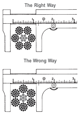
Measure the wire rope using a parallel-jawed caliper as discussed in Measuring Rope Diameter at the top of this page. If the rope is the wrong size or outside the recommended tolerance, return the rope to the wire rope supplier. It is never recommended nor permitted by federal standards to operate cranes with the incorrect rope diameter. Doing so will affect the safety factor or reduce service life and damage the sheaves and drum. Note that in a grooved drum application, the pitch of the groove may be designed for the rope’s nominal diameter and not the actual diameter as permitted by federal standards.
Wire rope can be permanently damaged by improper unreeling or uncoiling practices. The majority of wire rope performance problems start here.Improper unreeling practices lead to premature rope replacement, hoisting problems and rope failure.
Place the payout reel as far away from the boom tip as is practical, moving away from the crane chassis. Never place the payout reel closer to the crane chassis than the boom point sheave. Doing so may introduce a reverse bend into the rope and cause spooling problems. Follow the guidelines highlighted under Unreeling and Uncoiling and Drum Winding. Take care to determine whether the wire rope will wind over or under the drum before proceeding. If the wire rope supplier secured the end of the rope to the reel by driving a nail through the strands, ask that in the future a U-bolt or other nondestructive tie-down method be used; nails used in this manner damage the rope.
Take extra precaution when installing lang lay, rotation-resistant, flattened strand or compacted ropes. Loss of twist must be avoided to prevent the strands from becoming loosened, causing looped wire problems.
The end of the rope must be securely and evenly attached to the drum anchorage point by the method recommended by the equipment manufacturer. Depending on the crane’s regulatory requirements, at least two to three wraps must remain on the drum as dead wraps when the rope is unwound during normal operations. Locate the dead end rope anchorage point on the drum in relation to the direction of the lay of the rope. Do not use an anchorage point that does not correspond with the rope lay. Mismatching rope lay and anchorage point will cause the wraps to spread apart from each other and allow the rope to cross over on the drum. Very gappy winding will occur resulting in crushing damage in multilayer applications.
Back tension must be continually applied to the payout reel and the crewman installing the rope must proceed at a slow and steady pace whether the drum is smooth or grooved.Regardless of the benefits of a grooved drum, tension must be applied to ensure proper spooling. An improperly installed rope on a grooved drum will wear just as quickly as an improperly installed rope on a smooth drum. If a wire rope is poorly wound and as a result jumps the grooves, it will be crushed and cut under operating load conditions where it crosses the grooves.
Every wrap on the first or foundation layer must be installed very tightly and be without gaps. Careless winding results in poor spooling and will eventually lead to short service life. The following layers of rope must lay in the grooves formed between adjacent turns of the preceding layer of rope. If any type of overwind or cross-winding occurs at this stage of installation and is not corrected immediately, poor spooling and crushing damage will occur.
On a multilayer spooling drum be sure that the last layer remains at least two rope diameters below the drum flange top. Do not use a longer length than is required because the excess wire rope will cause unnecessary crushing and may jump the flange. Loose wraps that occur at any time must be corrected immediately to prevent catastrophic rope failure.
The use of a mallet is acceptable to ensure tight wraps, however a steel-faced mallet should be covered with plastic or rubber to prevent damage to the rope wires and strands.
Rotation-resistant ropes of all constructions require extra care in handling to prevent rope damage during installation. The lay length of a rotation-resistant rope must not be disturbed during the various stages of installation. By introducing twist or torque into the rope, core slippage may occur—the outer strands become shorter in length, the core slips and protrudes from the rope. In this condition the outer strands become over- loaded because the core is no longer taking its designed share of the load. Conversely, when torque is removed from a rotation-resistant rope core slippage can also occur. The outer strands become longer and the inner layers or core become overloaded, reducing service life and causing rope failure.
The plain end of a wire rope must be properly secured. If the entire cross section of the rope is not firmly secured, core slippage may occur, causing the core to pull inside the rope’s end and allowing it to protrude elsewhere, either through the outer strands (popped core) or out the other end of the line. The outer layer of the outside strands may also become overloaded as there is no complete core-to-strand support.
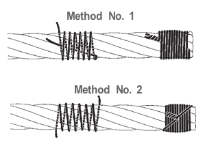
Secure the ends of the rope with either seizing or welding methods as recommended under Seizing Wire Rope. It is imperative that the ends be held together tightly and uniformly throughout the entire installation procedure, including attaching the end through the wedge socket and the drum dead end wedge
When installing a new line, connect the old line to the new line by using a swivel-equipped cable snake or Chinese finger securely attached to the rope ends. The connection between the ropes during change-out must be very strong and prevent torque from the old rope being transferred into the new rope.Welding ropes together or using a cable snake without the benefit of a swivel increases the likelihood of introducing torque into the new rope. A swivel-equipped cable snake is not as easy as welding the ropes, but this procedure can be mastered with a little patience and practice.
The condition and dimensions of the rope grooves in rums and rope sheaves must be checked to ensure that they comply with the specifications. If the new rope is used with an auxiliary rope of lower diameter, a non-rotating, rope design or a synthetic rope construction can be selected.
Will the new rope was pulled in with the old rope, the ends should be connected with a swivel. Twists from the old rope can occur during the pulling process and will eliminated by the swivel.
The load which a new wire rope may handle under given operating conditions and at an assumed design factor. A design factor of five is chosen most frequently for wire rope. (Operating loads not to exceed 20% of catalog breaking strength). Operating loads may have to be reduced when life, limb, or valuable property are at risk, or other than new wire rope is used. A design factor of 10 is usually chosen when wire rope is used to carry personnel. (Operating loads not to exceed 10% of catalog breaking strength). Responsibility for choosing a design factor with the user.
Rope sockets, thimbles, sleeves, hooks, links, shackles, sheaves, blocks, etc., must match in size, materials and strength, to provide adequate safety protection. Proper installation is crucial for maximum efficiency and safety.
In stricter senses, the term wire rope refers to a diameter larger than 9.5 mm (3⁄8 in), with smaller gauges designated cable or cords.wrought iron wires were used, but today steel is the main material used for wire ropes.
Historically, wire rope evolved from wrought iron chains, which had a record of mechanical failure. While flaws in chain links or solid steel bars can lead to catastrophic failure, flaws in the wires making up a steel cable are less critical as the other wires easily take up the load. While friction between the individual wires and strands causes wear over the life of the rope, it also helps to compensate for minor failures in the short run.
Wire ropes were developed starting with mining hoist applications in the 1830s. Wire ropes are used dynamically for lifting and hoisting in cranes and elevators, and for transmission of mechanical power. Wire rope is also used to transmit force in mechanisms, such as a Bowden cable or the control surfaces of an airplane connected to levers and pedals in the cockpit. Only aircraft cables have WSC (wire strand core). Also, aircraft cables are available in smaller diameters than wire rope. For example, aircraft cables are available in 1.2 mm (3⁄64 in) diameter while most wire ropes begin at a 6.4 mm (1⁄4 in) diameter.suspension bridges or as guy wires to support towers. An aerial tramway relies on wire rope to support and move cargo overhead.
Modern wire rope was invented by the German mining engineer Wilhelm Albert in the years between 1831 and 1834 for use in mining in the Harz Mountains in Clausthal, Lower Saxony, Germany.chains, such as had been used before.
Wilhelm Albert"s first ropes consisted of three strands consisting of four wires each. In 1840, Scotsman Robert Stirling Newall improved the process further.John A. Roebling, starting in 1841suspension bridge building. Roebling introduced a number of innovations in the design, materials and manufacture of wire rope. Ever with an ear to technology developments in mining and railroading, Josiah White and Erskine Hazard, principal ownersLehigh Coal & Navigation Company (LC&N Co.) — as they had with the first blast furnaces in the Lehigh Valley — built a Wire Rope factory in Mauch Chunk,Pennsylvania in 1848, which provided lift cables for the Ashley Planes project, then the back track planes of the Summit Hill & Mauch Chunk Railroad, improving its attractiveness as a premier tourism destination, and vastly improving the throughput of the coal capacity since return of cars dropped from nearly four hours to less than 20 minutes. The decades were witness to a burgeoning increase in deep shaft mining in both Europe and North America as surface mineral deposits were exhausted and miners had to chase layers along inclined layers. The era was early in railroad development and steam engines lacked sufficient tractive effort to climb steep slopes, so incline plane railways were common. This pushed development of cable hoists rapidly in the United States as surface deposits in the Anthracite Coal Region north and south dove deeper every year, and even the rich deposits in the Panther Creek Valley required LC&N Co. to drive their first shafts into lower slopes beginning Lansford and its Schuylkill County twin-town Coaldale.
The German engineering firm of Adolf Bleichert & Co. was founded in 1874 and began to build bicable aerial tramways for mining in the Ruhr Valley. With important patents, and dozens of working systems in Europe, Bleichert dominated the global industry, later licensing its designs and manufacturing techniques to Trenton Iron Works, New Jersey, USA which built systems across America. Adolf Bleichert & Co. went on to build hundreds of aerial tramways around the world: from Alaska to Argentina, Australia and Spitsbergen. The Bleichert company also built hundreds of aerial tramways for both the Imperial German Army and the Wehrmacht.
In the last half of the 19th century, wire rope systems were used as a means of transmitting mechanical powercable cars. Wire rope systems cost one-tenth as much and had lower friction losses than line shafts. Because of these advantages, wire rope systems were used to transmit power for a distance of a few miles or kilometers.
Steel wires for wire ropes are normally made of non-alloy carbon steel with a carbon content of 0.4 to 0.95%. The very high strength of the rope wires enables wire ropes to support large tensile forces and to run over sheaves with relatively small diameters.
In the mostly used parallel lay strands, the lay length of all the wire layers is equal and the wires of any two superimposed layers are parallel, resulting in linear contact. The wire of the outer layer is supported by two wires of the inner layer. These wires are neighbors along the whole length of the strand. Parallel lay strands are made in one operation. The endurance of wire ropes with this kind of strand is always much greater than of those (seldom used) with cross lay strands. Parallel lay strands with two wire layers have the construction Filler, Seale or Warrington.
In principle, spiral ropes are round strands as they have an assembly of layers of wires laid helically over a centre with at least one layer of wires being laid in the opposite direction to that of the outer layer. Spiral ropes can be dimensioned in such a way that they are non-rotating which means that under tension the rope torque is nearly zero. The open spiral rope consists only of round wires. The half-locked coil rope and the full-locked coil rope always have a centre made of round wires. The locked coil ropes have one or more outer layers of profile wires. They have the advantage that their construction prevents the penetration of dirt and water to a greater extent and it also protects them from loss of lubricant. In addition, they have one further very important advantage as the ends of a broken outer wire cannot leave the rope if it has the proper dimensions.
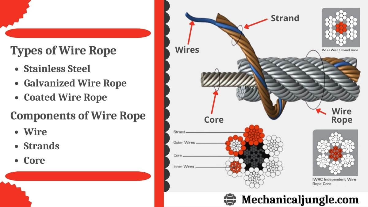
Stranded ropes are an assembly of several strands laid helically in one or more layers around a core. This core can be one of three types. The first is a fiber core, made up of synthetic material or natural fibers like sisal. Synthetic fibers are stronger and more uniform but cannot absorb much lubricant. Natural fibers can absorb up to 15% of their weight in lubricant and so protect the inner wires much better from corrosion than synthetic fibers do. Fiber cores are the most flexible and elastic, but have the downside of getting crushed easily. The second type, wire strand core, is made up of one additional strand of wire, and is typically used for suspension. The third type is independent wire rope core (IWRC), which is the most durable in all types of environments.ordinary lay rope if the lay direction of the wires in the outer strands is in the opposite direction to the lay of the outer strands themselves. If both the wires in the outer strands and the outer strands themselves have the same lay direction, the rope is called a lang lay rope (from Dutch langslag contrary to kruisslag,Regular lay means the individual wires were wrapped around the centers in one direction and the strands were wrapped around the core in the opposite direction.
Multi-strand ropes are all more or less resistant to rotation and have at least two layers of strands laid helically around a centre. The direction of the outer strands is opposite to that of the underlying strand layers. Ropes with three strand layers can be nearly non-rotating. Ropes with two strand layers are mostly only low-rotating.
Stationary ropes, stay ropes (spiral ropes, mostly full-locked) have to carry tensile forces and are therefore mainly loaded by static and fluctuating tensile stresses. Ropes used for suspension are often called cables.
Track ropes (full locked ropes) have to act as rails for the rollers of cabins or other loads in aerial ropeways and cable cranes. In contrast to running ropes, track ropes do not take on the curvature of the rollers. Under the roller force, a so-called free bending radius of the rope occurs. This radius increases (and the bending stresses decrease) with the tensile force and decreases with the roller force.
Wire rope slings (stranded ropes) are used to harness various kinds of goods. These slings are stressed by the tensile forces but first of all by bending stresses when bent over the more or less sharp edges of the goods.
Technical regulations apply to the design of rope drives for cranes, elevators, rope ways and mining installations. Factors that are considered in design include:
Donandt force (yielding tensile force for a given bending diameter ratio D/d) - strict limit. The nominal rope tensile force S must be smaller than the Donandt force SD1.
The wire ropes are stressed by fluctuating forces, by wear, by corrosion and in seldom cases by extreme forces. The rope life is finite and the safety is only ensured by inspection for the detection of wire breaks on a reference rope length, of cross-section loss, as well as other failures so that the wire rope can be replaced before a dangerous situation occurs. Installations should be designed to facilitate the inspection of the wire ropes.
Lifting installations for passenger transportation require that a combination of several methods should be used to prevent a car from plunging downwards. Elevators must have redundant bearing ropes and a safety gear. Ropeways and mine hoistings must be permanently supervised by a responsible manager and the rope must be inspected by a magnetic method capable of detecting inner wire breaks.
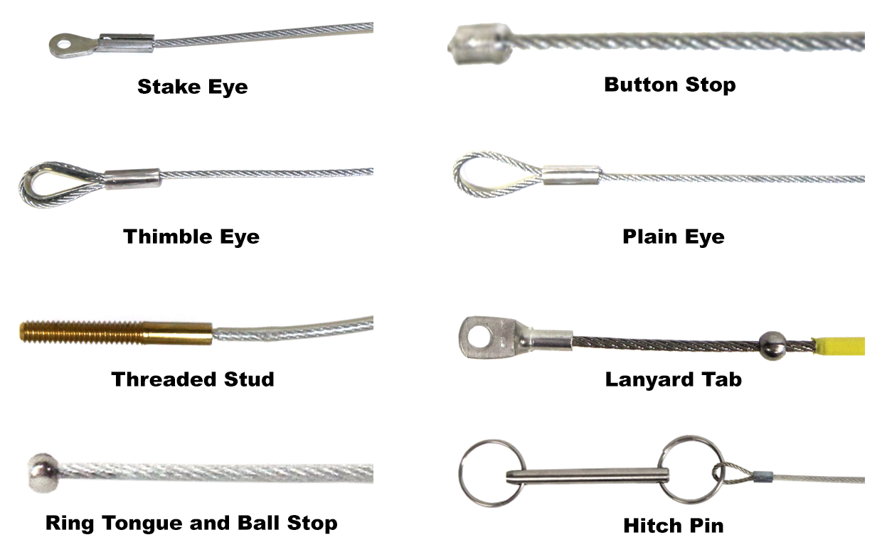
The end of a wire rope tends to fray readily, and cannot be easily connected to plant and equipment. There are different ways of securing the ends of wire ropes to prevent fraying. The common and useful type of end fitting for a wire rope is to turn the end back to form a loop. The loose end is then fixed back on the wire rope. Termination efficiencies vary from about 70% for a Flemish eye alone; to nearly 90% for a Flemish eye and splice; to 100% for potted ends and swagings.
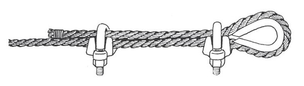
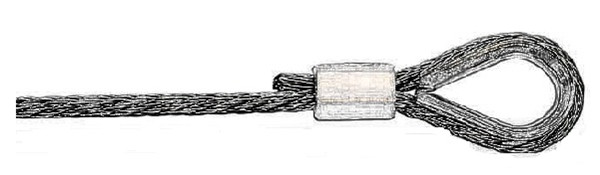
When the wire rope is terminated with a loop, there is a risk that it will bend too tightly, especially when the loop is connected to a device that concentrates the load on a relatively small area. A thimble can be installed inside the loop to preserve the natural shape of the loop, and protect the cable from pinching and abrading on the inside of the loop. The use of thimbles in loops is industry best practice. The thimble prevents the load from coming into direct contact with the wires.
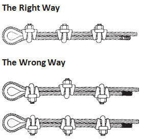
A wire rope clip, sometimes called a clamp, is used to fix the loose end of the loop back to the wire rope. It usually consists of a U-bolt, a forged saddle, and two nuts. The two layers of wire rope are placed in the U-bolt. The saddle is then fitted to the bolt over the ropes (the saddle includes two holes to fit to the U-bolt). The nuts secure the arrangement in place. Two or more clips are usually used to terminate a wire rope depending on the diameter. As many as eight may be needed for a 2 in (50.8 mm) diameter rope.
The mnemonic "never saddle a dead horse" means that when installing clips, the saddle portion of the assembly is placed on the load-bearing or "live" side, not on the non-load-bearing or "dead" side of the cable. This is to protect the live or stress-bearing end of the rope against crushing and abuse. The flat bearing seat and extended prongs of the body are designed to protect the rope and are always placed against the live end.
An eye splice may be used to terminate the loose end of a wire rope when forming a loop. The strands of the end of a wire rope are unwound a certain distance, then bent around so that the end of the unwrapped length forms an eye. The unwrapped strands are then plaited back into the wire rope, forming the loop, or an eye, called an eye splice.
A Flemish eye, or Dutch Splice, involves unwrapping three strands (the strands need to be next to each other, not alternates) of the wire and keeping them off to one side. The remaining strands are bent around, until the end of the wire meets the "V" where the unwrapping finished, to form the eye. The strands kept to one side are now re-wrapped by wrapping from the end of the wire back to the "V" of the eye. These strands are effectively rewrapped along the wire in the opposite direction to their original lay. When this type of rope splice is used specifically on wire rope, it is called a "Molly Hogan", and, by some, a "Dutch" eye instead of a "Flemish" eye.
Swaging is a method of wire rope termination that refers to the installation technique. The purpose of swaging wire rope fittings is to connect two wire rope ends together, or to otherwise terminate one end of wire rope to something else. A mechanical or hydraulic swager is used to compress and deform the fitting, creating a permanent connection. Threaded studs, ferrules, sockets, and sleeves are examples of different swaged terminations.
A wedge socket termination is useful when the fitting needs to be replaced frequently. For example, if the end of a wire rope is in a high-wear region, the rope may be periodically trimmed, requiring the termination hardware to be removed and reapplied. An example of this is on the ends of the drag ropes on a dragline. The end loop of the wire rope enters a tapered opening in the socket, wrapped around a separate component called the wedge. The arrangement is knocked in place, and load gradually eased onto the rope. As the load increases on the wire rope, the wedge become more secure, gripping the rope tighter.
Poured sockets are used to make a high strength, permanent termination; they are created by inserting the wire rope into the narrow end of a conical cavity which is oriented in-line with the intended direction of strain. The individual wires are splayed out inside the cone or "capel", and the cone is then filled with molten lead-antimony-tin (Pb80Sb15Sn5) solder or "white metal capping",zincpolyester resin compound.
Donald Sayenga. "Modern History of Wire Rope". History of the Atlantic Cable & Submarine Telegraphy (atlantic-cable.com). Archived from the original on 3 February 2014. Retrieved 9 April 2014.


 8613371530291