
wire rope lifting capacity chart manufacturer

If you are performing calculations involving the load of bridles and basket hitches, it’s important to use a wire rope sling capacity chart and also remember that as a reduction in the horizontal angle of the sling occurs the load imposed upon each leg increases. With bridles consisting of three or more legs, the horizontal…
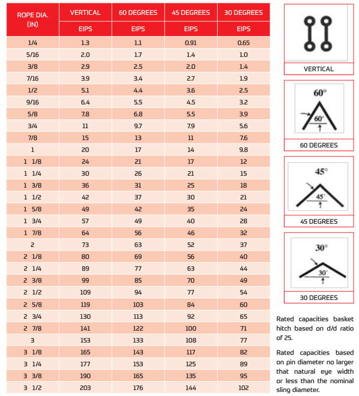
Rated load based on pin diameter no larger than one half the natural eye length or not less than the nominal sling diameter. Basket hitch capacity based on minimum D/d ratio of 25/1. For choker hitch, the angle of choke shall be 120 degrees or greater. For sling angles other than those shown, use the rated load for the next lower angle or a qualified person shall calculate the rated load. Horizontal sling angles of less than 30 degrees are not recommended. The capacity of a bridle at a 30 degree horizontal is same as single vertical leg.
The end point in a wire rope sling’s useful service life is prior to the failure of the sling. It must be removed from service when normal wear or accidental damage weakens the sling to the degree that an adequate factor of safety no longer exists.
The term “Breaking Strength” is never used with reference to slings. Slings have a “Rated Capacity” that is determined by the manufacturer. A sling should never be used to lift a load that is greater than the published “Rated Capacity” for the particular sling and for the type of hitch being used. The design factor used in the calculation of a sling’s Rated Capacity compensates for normal dynamic loading and builds useful life into the sling.
Selection of a sling to lift a load is based on selecting a sling with a Rated Capacity at least equal to the weight of the load. The sling must also be proper to allow the user to select a hitch that will conform to the shape of the load and keep it under control during the lift, The use of multiple leg slings is not recommended when the angle between any leg and the vertical is greater than 450• In any case when lifting headroom is restricted and a larger leg angle is necessary, care must be exercised in selecting a sling with a proper Rated Capacity at the leg angle which will be used. A visual inspection of the sling must be conducted before each lift to make sure the sling is in new or near new condition. A manufacturer’s Rated Capacity applies only to an undamaged sling.
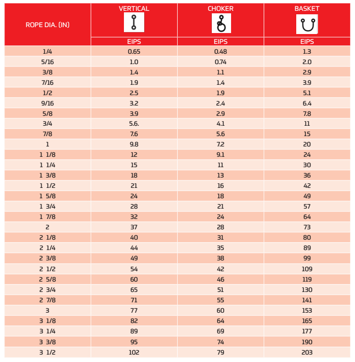
VERTICAL, or straight, attachment is simply using a sling to connect a lifting hook to a load. Full rated lifting capacity of the sling may be utilized, but must not be exceeded. A tagline should be used to prevent load rotation, which may damage a sling.
When two or more slings are attached to the same lifting hook, the total hitch becomes, in effect, a lifting bridle, and the load is distributed equally among the individual slings.
CHOKERhitches reduce lifting capability of a sling since this method of rigging affects ability of the wire rope components to adjust during the lift. A choker is used when the load will not be seriously damaged by the sling body — or the sling damaged by the load, and when the lift requires the sling to snug up against the load.
The diameter of the bend where the sling contacts the load should keep the point of choke against the sling BODY — never against a splice or the base of the eye. When a choke is used at an angle of less than 120 degrees (see next page), the sling-rated capacity must be adjusted downward.
Anytime pull is exerted at an angle on a leg—or legs—of a sling, the load per leg can be determined by using the data in the table above. Proceed as follows to calculate this load—and determine the rated capacity required of the sling, or slings, needed for a lift.First, divide the total load to be lifted by the number of legs to be used. This provides the load per leg if the lift were being made with all legs being vertically.
Then MULTIPLY the load per leg (as computed above) by the Load Factor for the leg angle being used (from the table at the bottom) – to compute the ACTUAL LOAD on each leg for this lift and angle. THE ACTUAL LOAD MUST NOT EXCEED THE RATED SLING CAPACITY.
The horizontal angle of bridles with 3 or more legs is measured the same as the horizontal sling angle of 2-legged hitches. In this case, where a bridle designed with different leg lengths results in horizontal angles, the leg with the smallest horizontal angle will carry the greatest load. Therefore, the smallest horizontal angle is used in calculating actual leg load and evaluating the rated capacity of the sling proposed.
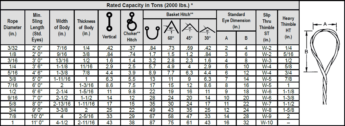
On the other hand, the eye should always be used on a hook or pin with at least the nominal diameter of the rope—since applying the D/d Ratio shows an efficiency loss of approximately 50% when the relationship is less than 1/1.
When rigged as a basket, DIAMETER of the bend where a sling contacts the load can be a limiting factor on sling capacity. Standard D/d ratios— where “D” is the diameter of bend, and “d” the diameter of the rope—are applied to determine efficiency of various sling constructions, as indicated below:Mechanically Spliced, Single-Part Slings: 25 times rope diameter
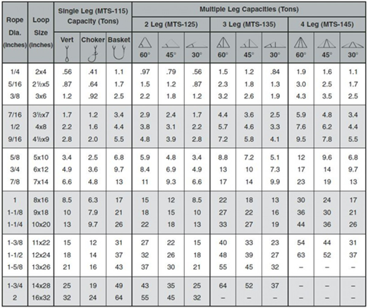
Whether to use a single-part sling (one made of a single wire rope in the sling body) or a multi-part sling (several ropes in the body) is usually the first decision to make after determining the sling length and capacity for a lift.
The starting point for this decision involves the handling characteristics of the sling more than any other factor. Based on capacity alone, multi-part slings will be more flexible…more easily handled…than single-part slings. The larger the capacity of a sling, the more important this becomes…to the point, it becomes unrealistic to build big capacity slings from single, very large wire ropes.
In the design of the sling, rope engineers must seek a balance between strength-handling characteristics and number of parts…since there is a tendency to lose strength as core parts are added to increase flexibility.
If a load is hanging free, the normal choke angle is approximately 135 degrees. When the angle is less than 135 degrees, an adjustment in the sling-rated capacity must be made. Choker hitches at angles greater than 135 degrees are not recommended since they are unstable.
This is the length of wire rope between splices, sleeves or fittings. Generally, the minimum body length is equal to ten (10) times the sling body diameter. This allows approximately one and one half (1-1/2) rope lays between splices. For Multi-part slings, the minimum body length between splices is equal to forty (40) times the component rope diameter.
Wire rope is often used in slings because of its strength, durability, abrasion resistance and ability to conform to the shape of the loads on which it is used. In addition, wire rope slings are able to lift hot materials.
Wire rope used in slings can be made of ropes with either Independent Wire Rope Core (IWRC) or a fiber-core. It should be noted that a sling manufactured with a fiber-core is usually more flexible but is less resistant to environmental damage. Conversely, a core that is made of a wire rope strand tends to have greater strength and is more resistant to heat damage.
Wire rope may be manufactured using different rope lays. The lay of a wire rope describes the direction the wires and strands are twisted during the construction of the rope. Most wire rope is right lay, regular lay. This type of rope has the widest range of applications. Wire rope slings may be made of other wire rope lays at the recommendation of the sling manufacturer or a qualified person.
Wire rope slings are made from various grades of wire rope, but the most common grades in use are Extra Improved Plow Steel (EIPS) and Extra Extra Improved Plow Steel (EEIPS). These wire ropes are manufactured and tested in accordance with ASTM guidelines. If other grades of wire rope are used, use them in accordance with the manufacturer"s recommendations and guidance.
When selecting a wire rope sling to give the best service, consider four characteristics: strength, ability to bend without distortion, ability to withstand abrasive wear, and ability to withstand abuse.
Rated loads (capacities) for single-leg vertical, choker, basket hitches, and two-, three-, and four-leg bridle slings for specific grades of wire rope slings are as shown in Tables 7 through 15.
Ensure that slings made of rope with 6×19 and 6x37 classifications and cable slings have a minimum clear length of rope 10 times the component rope diameter between splices, sleeves, or end fittings unless approved by a qualified person,
Ensure that braided slings have a minimum clear length of rope 40 times the component rope diameter between the loops or end fittings unless approved by a qualified person,
Do not use wire rope clips to fabricate wire rope slings, except where the application precludes the use of prefabricated slings and where the sling is designed for the specific application by a qualified person,
Ensure that wire rope slings have suitable characteristics for the type of load, hitch, and environment in which they will be used and that they are not used with loads in excess of the rated load capacities described in the appropriate tables. When D/d ratios (Fig. 4) are smaller than those listed in the tables, consult the sling manufacturer. Follow other safe operating practices, including:
When D/d ratios (see Fig. 6) smaller than those cited in the tables are necessary, ensure that the rated load of the sling is decreased. Consult the sling manufacturer for specific data or refer to the WRTB (Wire Rope Technical Board) Wire Rope Sling Users Manual, and
Before initial use, ensure that all new swaged-socket, poured-socket, turnback-eye, mechanical joint grommets, and endless wire rope slings are proof tested by the sling manufacturer or a qualified person.
Permanently remove from service fiber-core wire rope slings of any grade if they are exposed to temperatures in excess of 180 degrees F (82 degrees C).
Follow the recommendations of the sling manufacturer when you use metallic-core wire rope slings of any grade at temperatures above 400 degrees F (204 degrees C) or below minus 40 degrees F (minus 40 degrees C).


 8613371530291