
wire rope lifting capacity chart brands
- Recovery Ropes, Tow Lines, Tow Bridles, Tow Ropes, Winch Ropes, & Winch Lines- - Recovery Ropes, Tow Lines, Tow Bridles, Tow Ropes, Winch Ropes, & Winch Lines – Main Page
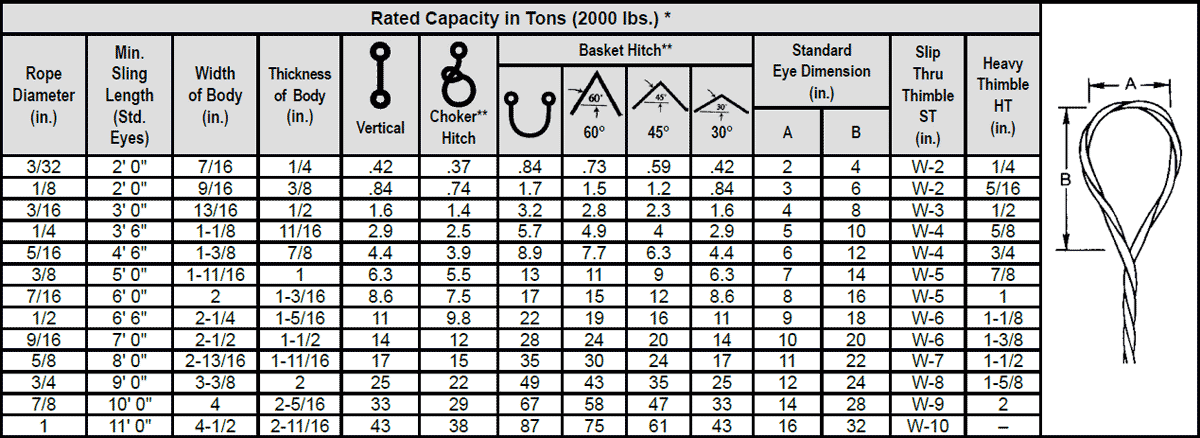
VERTICAL, or straight, attachment is simply using a sling to connect a lifting hook to a load. Full rated lifting capacity of the sling may be utilized, but must not be exceeded. A tagline should be used to prevent load rotation, which may damage a sling.
When two or more slings are attached to the same lifting hook, the total hitch becomes, in effect, a lifting bridle, and the load is distributed equally among the individual slings.
CHOKERhitches reduce lifting capability of a sling since this method of rigging affects ability of the wire rope components to adjust during the lift. A choker is used when the load will not be seriously damaged by the sling body — or the sling damaged by the load, and when the lift requires the sling to snug up against the load.
The diameter of the bend where the sling contacts the load should keep the point of choke against the sling BODY — never against a splice or the base of the eye. When a choke is used at an angle of less than 120 degrees (see next page), the sling-rated capacity must be adjusted downward.
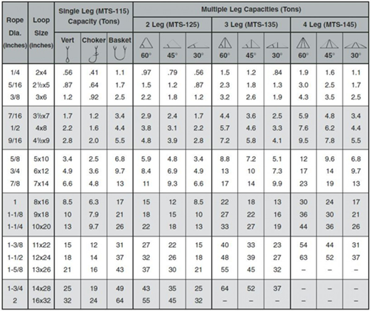
Anytime pull is exerted at an angle on a leg—or legs—of a sling, the load per leg can be determined by using the data in the table above. Proceed as follows to calculate this load—and determine the rated capacity required of the sling, or slings, needed for a lift.First, divide the total load to be lifted by the number of legs to be used. This provides the load per leg if the lift were being made with all legs being vertically.
Then MULTIPLY the load per leg (as computed above) by the Load Factor for the leg angle being used (from the table at the bottom) – to compute the ACTUAL LOAD on each leg for this lift and angle. THE ACTUAL LOAD MUST NOT EXCEED THE RATED SLING CAPACITY.
The horizontal angle of bridles with 3 or more legs is measured the same as the horizontal sling angle of 2-legged hitches. In this case, where a bridle designed with different leg lengths results in horizontal angles, the leg with the smallest horizontal angle will carry the greatest load. Therefore, the smallest horizontal angle is used in calculating actual leg load and evaluating the rated capacity of the sling proposed.
On the other hand, the eye should always be used on a hook or pin with at least the nominal diameter of the rope—since applying the D/d Ratio shows an efficiency loss of approximately 50% when the relationship is less than 1/1.
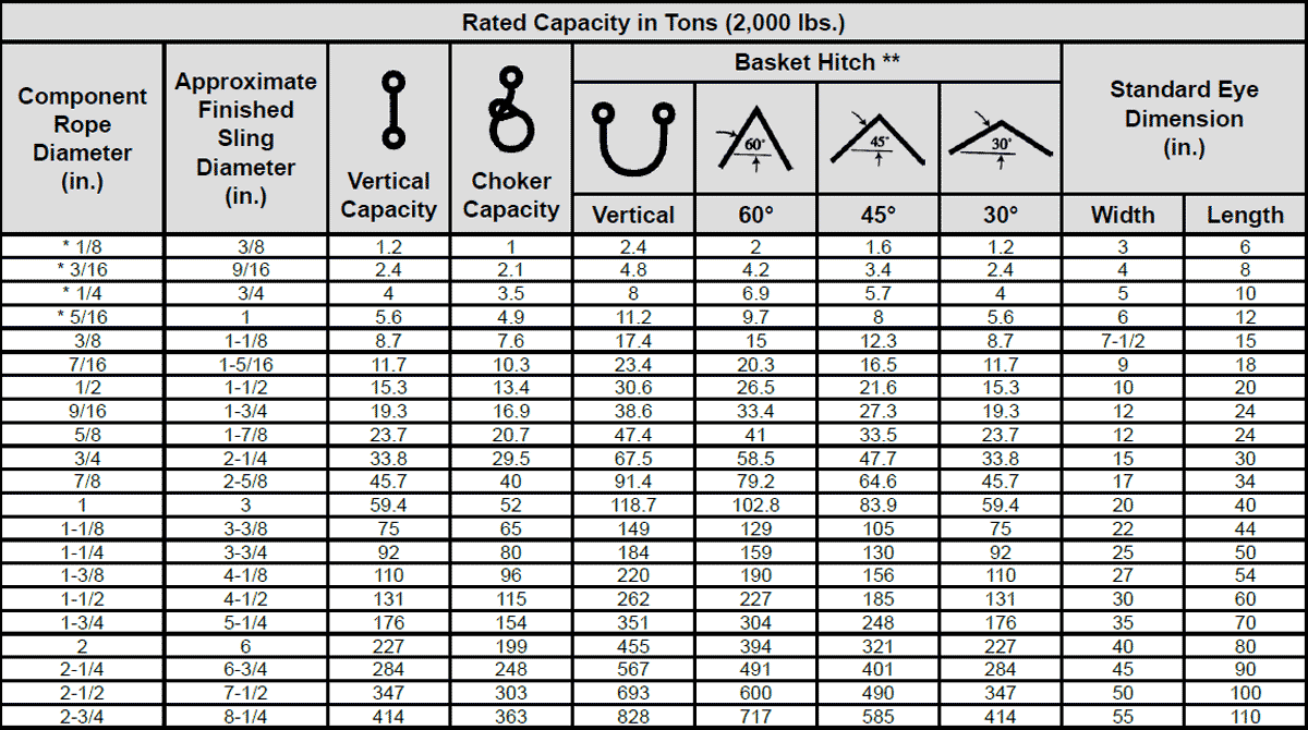
When rigged as a basket, DIAMETER of the bend where a sling contacts the load can be a limiting factor on sling capacity. Standard D/d ratios— where “D” is the diameter of bend, and “d” the diameter of the rope—are applied to determine efficiency of various sling constructions, as indicated below:Mechanically Spliced, Single-Part Slings: 25 times rope diameter
Whether to use a single-part sling (one made of a single wire rope in the sling body) or a multi-part sling (several ropes in the body) is usually the first decision to make after determining the sling length and capacity for a lift.
The starting point for this decision involves the handling characteristics of the sling more than any other factor. Based on capacity alone, multi-part slings will be more flexible…more easily handled…than single-part slings. The larger the capacity of a sling, the more important this becomes…to the point, it becomes unrealistic to build big capacity slings from single, very large wire ropes.
In the design of the sling, rope engineers must seek a balance between strength-handling characteristics and number of parts…since there is a tendency to lose strength as core parts are added to increase flexibility.
If a load is hanging free, the normal choke angle is approximately 135 degrees. When the angle is less than 135 degrees, an adjustment in the sling-rated capacity must be made. Choker hitches at angles greater than 135 degrees are not recommended since they are unstable.
This is the length of wire rope between splices, sleeves or fittings. Generally, the minimum body length is equal to ten (10) times the sling body diameter. This allows approximately one and one half (1-1/2) rope lays between splices. For Multi-part slings, the minimum body length between splices is equal to forty (40) times the component rope diameter.
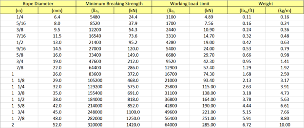
Rope strength is a misunderstood metric. One boater will talk about tensile strength, while the other will talk about working load. Both of these are important measurements, and it’s worth learning how to measure and understand them. Each of these measurements has different uses, and here we’re going to give a brief overview of what’s what. Here’s all you need to know about rope strength.
Each type of line, natural fiber, synthetic and wire rope, have different breaking strengths and safe working loads. Natural breaking strength of manila line is the standard against which other lines are compared. Synthetic lines have been assigned “comparison factors” against which they are compared to manila line. The basic breaking strength factor for manila line is found by multiplying the square of the circumference of the line by 900 lbs.
Just being able to calculate breaking strength doesn’t give one a safety margin. The breaking strength formula was developed on the average breaking strength of a new line under laboratory conditions. Without straining the line until it parts, you don’t know if that particular piece of line was above average or below average. For more information, we have discussed the safe working load of ropes made of different materials in this article here.
It’s very important to understand the fundamental differences between the tensile strength of a rope, and a rope’s working load. Both terms refer to rope strength but they’re not the same measurement.
A rope’s tensile strength is the measure of a brand-new rope’s breaking point tested under strict laboratory-controlled conditions. These tests are done by incrementally increasing the load that a rope is expected to carry, until the rope breaks. Rather than adding weight to a line, the test is performed by wrapping the rope around two capstans that slowly turn the rope, adding increasing tension until the rope fails. This test will be repeated on numerous ropes, and an average will be taken. Note that all of these tests will use the ASTM test method D-6268.
The average number will be quoted as the rope’s tensile strength. However, a manufacturer may also test a rope’s minimum tensile strength. This number is often used instead. A rope’s minimum tensile strength is calculated in the same way, but it takes the average strength rating and reduces it by 20%.
A rope’s working load is a different measurement altogether. It’s determined by taking the tensile strength rating and dividing it accordingly, making a figure that’s more in-line with an appropriate maximum load, taking factors such as construction, weave, and rope longevity into the mix as well. A large number of variables will determine the maximum working load of a rope, including the age and condition of the rope too. It’s a complicated equation (as demonstrated above) and if math isn’t your strong point, it’s best left to professionals.
However, if you want to make an educated guess at the recommended working load of a rope, it usually falls between 15% and 25% of the line’s tensile strength rating. It’s a lotlower than you’d think. There are some exceptions, and different construction methods yield different results. For example, a Nylon rope braided with certain fibers may have a stronger working load than a rope twisted out of natural fibers.
For safety purposes, always refer to the information issued by your rope’s manufacturer, and pay close attention to the working load and don’t exceed it. Safety first! Always.
If you’re a regular sailor, climber, or arborist, or just have a keen interest in knot-tying, be warned! Every knot that you tie will reduce your rope’s overall tensile strength. Some knots aren’t particularly damaging, while others can be devastating. A good rule of thumb is to accept the fact that a tied knot will reduce your rope’s tensile strength by around 50%. That’s an extreme figure, sure, but when it comes to hauling critical loads, why take chances?
Knots are unavoidable: they’re useful, practical, and strong. Splices are the same. They both degrade a rope’s strength. They do this because a slight distortion of a rope will cause certain parts of the rope (namely the outer strands) to carry more weight than others (the inner strand). In some cases, the outer strands end up carrying all the weight while the inner strands carry none of it! This isn’t ideal, as you can imagine.
Some knots cause certain fibers to become compressed, and others stretched. When combined together, all of these issues can have a substantial effect on a rope’s ability to carry loads.
Naturally, it’s not always as drastic as strength loss of 50% or more. Some knots aren’t that damaging, some loads aren’t significant enough to cause stress, and some rope materials, such as polypropylene, Dyneema, and other modern fibers, are more resilient than others. Just keep in mind that any knots or splices will reduce your rope’s operations life span. And that’s before we talk about other factors such as the weather or your rope care regime…
T he end of a single wire rope is bent back HAND-SPLICED EYE along the wire rope to form the eye. Strands are hand-tucked into the body of the ropein what is called a tapered and concealed splice.The splice makes a sling that can be easily pulledthrough narrow spaces because there are no roughends to snag on loads.
Slings with wire rope bodies larger than 1-1/2”diameter are made only with burnt end splices inwhich the ends of strands are left exposed andthen cut off with a torch. These ends may also The tapered and concealed splicebe cut shorter and served for smoothness. Either utilizes tension in the rope body tomethod has the same rated capacity, size for size. secure strands where they are tucked back into the rope. It doesn’t require aWarning: Hand-spliced slings should not be used metal sleeve to assure firm anchoring.in lifts where the sling may rotate and cause the When “tapered and concealed,” the ends of strands are tucked inward and thenwire rope to unlay. concealed inside the rope.
110 FC & IWRC RATED CAPACITY – Tons* E-E Basket Eye E-HT E-EH Hitch Dimensions Thimble Hook Rope Choker Dia. Hitch WLL** (in.) Vert. *** 60° 45° 30° A B A B Tons E R
All capacities in tons of 2,000 lbs. All eye and fitting dimensions in inches. * Rated Capacities Basket Hitch based on D/d Ratio of 15. Rated Capacities based on pin diameter no larger than natural eye width or less than the nominal sling diameter. Rated Capacities based on design factor of 5. Horizontal sling angles of less than 30° shall not be used. ** Working Load Limit, based on standard carbon fittingsunless noted otherwise. *** See Choker Hitch Rated Capacity Adjustment.
E yes are typically formed FLEMISH EYE SPLICE using a flemish eye splice. The ends are secured bypressing a metal sleeve over theends of the strands of the splice.Pull follows a direct line alongthe center of the rope andeye. Single part bodymechanical splice slingshave a higher ratedcapacity than hand-spliced slings. In the standard flemish eye mechanical splice, wire rope is separated into two parts: three adjacent strands to one part and three adjacent strands along with the core to the other part. The two parts are then re-laid back in opposite directions to form an eye and ends are secured with a pressed metal sleeve.
115 IWRC RATED CAPACITY – Tons* E-E Basket Eye E-HT E-EH Hitch Dimensions Thimble Hook Rope Choker Dia. Hitch WLL** (in.) Vert. *** 60° 45° 30° A B A B Tons E R
All capacities in tons of 2,000 lbs. All eye and fitting dimensions in inches. * Rated Capacities Basket Hitch based on D/d Ratio of 25. Rated Capacities based on pin diameter no larger than natural eye width or less than the nominal sling diameter. Rated Capacities based on design factor of 5. Horizontal sling angles less than 30° shall not be used. ** Working Load Limit, based on standard carbon fittings unless noted otherwise. *** See Choker Hitch Rated Capacity Adjustment on Page 7. Union A WireCo WorldGroup Brand 9Single part body, mechanically-spliced wire rope slings
TWO- AND MULTI-LEGGED BRIDLESTWO-LEGGED BRIDLES Whether used as chokers Rated capacities shownor with hooks or other end attachments, they are for multi-leg slings areaffected by rigging angles. Note the reduction in for slings that have allrated capacity as leg angles are reduced. legs the same length and all legs are equally sharingMULTI-LEGGED BRIDLES With two, three or the load being lifted.four straight legs, they are offered with plain eyes,thimble eyes, open sockets, closed sockets, shackles For other conditions,or turnbuckles. contact WireCo WorldGroup.
125-HT-EH IWRC RATED CAPACITY – Tons* Alloy Oblong Link Hook Rope Dia. WLL** (in.) 60° 45° 30° D L W Tons E R
10 Union A WireCo WorldGroup Brand 135-HT-EH RATED CAPACITY – Tons* Alloy Pear Link Hook Rope Dia. WLL** (in.) 60° 45° 30° A B C D Tons E R
145-HT-EH RATED CAPACITY – Tons* Alloy Pear Link Hook Rope Dia. WLL** (in.) 60° 45° 30° A B C D Tons E R
S UPER-FLEX® SLINGS are flexible SUPER-FLEX HAND SPLICE and can snug up tightly around Each sling is hand-fabricated the load in choker hitches. Super- by laying together one or Flex slings also offer outstanding more ropes in a helical handling characteristics, particularly in manner so component the larger rated capacities. When loaded, ropes run continuously stress distributes to all rope parts in through the eyes and THE ADVANTAGES the sling body due to the helical manner sling body. The ends OF SUPER-FLEX in which ropes are laid together. are then secured into SLINGS the component rope> Flexible enough to Braided slings are formed by continu- with hand-tucked snug up around the ously plaiting, or braiding, several splices. load, Super-Flex ropes together to form the sling body slings also handle and both eyes in a single fabrication SUPER-FLEX the load well, operation. Ends of the individual ropes MECHANICAL SPLICE particularly in the are usually hand-tucked or mechanically Three wire ropes are larger-rated spliced into the component ropes of the helically laid to form a capacities. body. The eyes are wrapped and given three-part fabric, from which sling a rubberized coating. bodies of three or nine parts may be made by helically laying Braided slings are often selected one or three parts when loads must either be turned or of fabric together. maneuvered since the sling design Mechanical splices creates friction to grip loads. form the eyes that provide centerline pull Four-, five- and seven-part Super-Flex along the sling body. slings with either mechanical or hand There are the same eye splices are available by special order. number of rope parts For further information, contact in the sling eyes as WireCo WorldGroup. in the body.
MULTI-PART BODY BRAIDED CONSTRUCTION High flexibility is achieved by braiding, or plaiting, one or more wire ropes to form a fabric for the sling body. Component ropes run continuously through the body and eyes with ends hand- tucked into sling body or secured with pressed sleeves. The six-part sling is flat; the eight-part is round.
12 Union A WireCo WorldGroup BrandSuper-Flex® multi-part body, single leg slings 310-315* FC RATED CAPACIT Y – Tons* Eye Dimensions Slip Thru Heavy Rope Thimble Thimble Dia. Sling Choker Basket (in.) Dia. Vert. Hitch Hitch A B ST HT
310-315* IWRC RATED CAPACIT Y – Tons* Eye Dimensions Slip Thru Heavy Rope Thimble Thimble Dia. Sling Choker Basket (in.) Dia. Vert. Hitch Hitch A B ST HT
* 315 assemblies 1” and larger have single sleeve on component rope. ** Rated Capacities Basket Hitch based on D/d ratio of 25 times the component rope diameter. # Made with 7x19 GAC component rope. Rated Capacities based on pin diameter no larger than natural eye width or less than the nominal sling diameter. Rated Capacities based on design factor of 5. Horizontal sling angles of less than 30° shall not be used. All capacities in tons of 2,000 lbs. All eye and fitting dimensions in inches.
Union A WireCo WorldGroup Brand 13Super-Flex® multi-part body, double leg slings
320-325* FC RATED CAPACIT Y – Tons* Alloy Oblong Links Slip Thru Heavy Rope Thimble Thimble Dia. Sling (in.) Dia. Vert. 60° 45° 30° D L W ST HT
320-325* IWRC RATED CAPACIT Y – Tons* Alloy Oblong Links Slip Thru Heavy Rope Thimble Thimble Dia. Sling (in.) Dia. Vert. 60° 45° 30° D L W ST HT
* 325 assemblies 1” and larger have single sleeve on component rope. # Made with 7x19 GAC component rope. Rated Capacities based on pin diameter no larger than natural eye width or less than the nominal sling diameter. Rated Capacities based on design factor of 5. Horizontal sling angles less than 30° shall not be used. All capacities in tons of 2,000 lbs. All eye and fitting dimensions in inches.
615 SIX-PART FL AT BRAIDED SLING RATED CAPACIT Y – Tons* Eye Dimensions Slip Thru Heavy Rope Thimble Thimble Dia. Width Thickness Choker Basket (in.) of Body of Body Vertical Hitch Hitch A B ST HT
# Made with 7x19 GAC component rope. * Rated Capacities Basket Hitch based on D/d ratio of 25 times the component rope diameter. ** See Choker Hitch Rated Capacity Adjustment on Page 7. Rated Capacities based on pin diameter no larger than natural eye width or less than the nominal sling diameter. Rated Capacities based on design factor of 5. Horizontal sling angles less than 30° shall not be used. All capacities in tons of 2,000 lbs. All eye and fitting dimensions in inches.
815 EIGHT-PART ROUND BRAIDED SLING RATED CAPACIT Y – Tons* Eye Dimensions Slip Thru Heavy Rope Thimble Thimble Dia. Sling Choker Basket (in.) Diameter Vertical Hitch Hitch A B ST HT
# Made with 7x19 GAC component rope. * Rated Capacities Basket Hitch based on D/d ratio of 25 times the component rope diameter. ** See Choker Hitch Rated Capacity Adjustment on Page 7. Rated Capacities based on pin diameter no larger than natural eye width or less than the nominal sling diameter. Rated Capacities based on design factor of 5. Horizontal sling angles less than 30° shall not be used. All capacities in tons of 2,000 lbs. All eye and fitting dimensions in inches.
LARGE CAPACITY 9-PART XIP® WIRE ROPE SLINGSFlexibility and handling ease for rigging large lifts Only two splices occur in the entire sling – whereare the main benefits of the 9-PART SLINGS. the two rope ends are spliced at the eyes.
The 9-part sling is made by laying wire rope contin- A 9-part sling construction exhibits constructionaluously through both eyes and the sling body. This stretch of approximately 1.5% on the first loadingresults in a body formed with nine parts. The proven and a lesser amount thereafter. For this reason, liftsdesign provides internal adjustment to distribute that use two or more legs should always be madethe load among all nine parts of the sling body. with legs that have been subjected to the same pastAdditionally, the construction makes it possible usage when such stretch may affect the lift.to more easily inspect all parts of the sling beforeand after each lift, which is important to remember When a sling body must conform to a tight chokeif the sling is to be used many times. hitch or must bend in a tight radius, such as around a pin or post, a 9-part construction may be the most suitable since it can develop greater lifting capacity from a smaller component rope.
915 NINE-PART WIRE ROPE SLING RATED CAPACIT Y – Tons* Basket Hitch & 2-Leg Bridles Eye Dimensions Weight XIP® IWRC Comp. Sling Rope Body Eye Eye Pounds Dia. Dia. Vert. Width Length per foot (in.) (in.) Vert. Choker Vert. 60° 45° 30° (in.) (in.) (approx.)
* Rated Capacities Basket Hitch based on D/d ratio of 25 times the component rope diameter.Rated Capacities based on pin diameter no larger than natural width or less than the nominal diameter.Rated Capacities based on design factor of 5.Horizontal sling angles of less than 30° shall not be used.** See Choker Hitch Rated Capacity Adjustment on Page 7.All capacities in tons of 2,000 lbs. All eye and fitting dimensions in inches.
HAND-SPLICE OR MECHANICALSPLICE GROMMETSGrommets either have a wire rope body The minimum circumferenceor a body made up of six strands which of the sling is 96 times theare laid helically around a strand core. grommet’s body diameter.Either a hand-splice or a mechanicalsplice then forms an endless sling body. Rope-laid grommets are also available.
* Rated Capacities Basket Hitch and vertical lift based on D/d ratio of 5 when “d” = body diameter of the finished grommet. Rated Capacities based on pin diameter no smaller than 5 times the body diameter. Rated Capacities based on design factor of 5. Horizontal sling angles of less than 30° shall not be used. See Choker Hitch Rated Capacity Adjustment on Page 7. All capacities in tons of 2000 lbs. All diameter dimensions in inches.
18 Union A WireCo WorldGroup Brand 215/715 STRAND L AID MECHANICAL SPLICE 270 CABLE L AID HAND SPLICE CONTINUOUS CONSTRUCTION RATED CAPACIT Y – Tons* RATED CAPACIT Y – Tons* Basket Hitch and 2-Leg Bridle Basket Hitch and 2-Leg Bridle XIP® XIP® Sling Sling Comp. Body Body Rope Dia. Vert. Choker Vert. 60° 45° 30° Dia. Dia. Vert. Choker Vert. 60° 45° 30°
7/8 12 8.7 25 22 18 12 15/16 5/16 8.7 5.6 17 15 12 8.7 1 16 11 32 28 23 16 1-1/8 3/8 12 8.0 25 21 17 12 1-1/8 20 14 41 35 29 20 1-5/16 7/16 17 11 33 29 23 17 1-1/4 25 17 50 43 35 25 1-1/2 1/2 21 14 43 37 30 21 1-3/8 30 21 60 52 42 30 1-11/16 9/16 27 17 53 46 38 27 1-1/2 36 25 71 62 50 36 1-7/8 5/8 33 21 66 57 46 33 1-5/8 41 29 82 71 58 41 2-1/4 3/4 46 30 92 80 65 46 1-3/4 48 33 95 83 68 48 2-5/8 7/8 62 40 123 107 87 62 1-7/8 54 38 109 94 77 54 3 1 79 51 158 137 112 79 2 62 43 124 107 87 62 3-3/8 1-1/8 98 64 196 170 138 98 2-1/8 69 48 138 119 98 69 3-3/4 1-1/4 119 77 237 205 168 119 2-1/4 77 54 154 133 109 77 2-3/8 85 60 171 148 121 85 * Rated Capacities Basket Hitch and vertical lift based on D/d ratio of 5 when “d” = body diameter of the finished grommet. 2-1/2 94 66 188 163 133 94 Rated Capacities based on pin diameter no smaller than 5 times the body diameter. 2-3/4 113 79 225 195 159 113 Rated Capacities based on design factor of 5. 3 133 93 265 230 188 133 Sling angles of less than 30° shall not be used. See Choker Hitch Rated Capacity Adjustment on Page 7. * Rated Capacities Basket Hitch and vertical lift based on D/d ratio of 5 when All capacities in tons of 2000 lbs. “d” = body diameter of the finished grommet. All diameter dimensions in inches. Rated Capacities based on pin diameter no smaller than 5 times the body diameter. Rated Capacities based on design factor of 5. Sling angles of less than 30° shall not be used. See Choker Hitch Rated Capacity Adjustment on Page 7. All capacities in tons of 2000 lbs. All diameter dimensions in inches.
WIRE ROPE ASSEMBLIES WITH SWAGEDAND SPELTER SOCKETSBoom pendants, guylines, raising lines, backstays, Both types of attachments develop 100% of thelifting bridles and more. Those are the uses of rope’s minimum breaking force.our wire rope assemblies, offered in both poured(spelter) sockets and mechanically swaged sockets. SPELTER SOCKETA Design Factor of five has been used to establish Molten zinc is the standard socketing material,the rated capacities seen in the charts. however, an epoxy socketing material can be specified. Both have the same Rated Capacity. SteelWhen ordering your assemblies, please indicate forgings are used on rope sizes 1/2” through 1-1/2”your choice of end fittings on your purchase order and cast steel fittings are used for larger sizes. Ropeby using the suffixes “OS” or “CS” after the model sizes larger than 4” are available on special order.number. “OS” indicates your preference for an opensocket fitting, while “CS” designates a closed fitting. The assembly lengths are measured from the centerline point of the pin for open sockets andPins and cotters are supplied as standard on open the bearing point for closed sockets.fittings only. Assemblies may be specified withoutpins. All fittings will be assembled with the pinholes in the same plane unless your order specifies 110 SPELTER SOCKETotherwise. RATED CAPACITY IWRC In Tons Rope of 2000 lbs. Dia. XIP® XXIP® #1/2 2.7 2.9 9/16 3.4 3.7 5/8 4.1 4.5 3/4 5.9 6.5 7/8 8.0 8.8 1 10 11 1-1/8 13 14 1-1/4 16 18 1-3/8 19 21 1-1/2 23 25 1-5/8 26 29 1-3/4 31 34 1-7/8 35 38 2 40 43 2-1/8 44 49 2-1/4 49 54 2-3/8 55 60 2-1/2 60 66 2-5/8 66 73 2-3/4 72 79 2-7/8 78 86 3 85 94 3-1/8 92 101 3-1/4 98 108 3-3/8 106 116 3-1/2 113 124 3-5/8 120 132 3-3/4 128 141 4 144 159
20 Union A WireCo WorldGroup Brand 110 OPEN SPELTER SOCKET 110 CLOSED SPELTER SOCKET Rope Diameter C D F J L M Rope Diameter B C D F J K L
SWAGED SOCKETIn mechanically swaged fittings, high Normally, only regularpressure presses and precision dies lay rope is used in thecause the metal of the socket to flow swaged sockets. Thearound the wires and strands to result swaged assemblies arein the ultimate compactness and interchangeable withstrength with minimum weight. poured sockets up through 2” ropeThe material is weldless, drop-forged diameters. Assemblysteel. length is measured from the centerline of pins for both open and closed swaged sockets.
115 SWAGED SOCKET RATED CAPACIT Y In Tons Rope of 2000 lbs. Dia. (in.) XIP® XXIP® #1/2 0.68 0.74 5/16 1.1 1.2 3/8 1.5 1.7 7/16 2.0 2.2 1/2 2.7 2.9 9/16 3.4 3.7 5/8 4.1 4.5 3/4 5.9 6.5 7/8 8.0 8.8 1 10 11 1-1/8 13 14 1-1/4 16 18 1-3/8 19 21 1-1/2 23 25 1-3/4 31 34 2 40 43 2-1/4 49 54 2-1/2 60 66
22 Union A WireCo WorldGroup Brand115 OPEN SWAGED SOCKET 115 CLOSED SWAGED SOCKET As Ls As Ls Max. Approx. Max. Approx. After After After After Rope Swage Swage Rope Swage Swage Dia. C D F N Pin Dia. Length Dia. C D E Dia. Length

Our CWC registered trademark BLUE STEEL™ is one of the strongest co-polymer ropes in the market today. The turquoise color fiber with two dark blue tracers have become the industry standard for high performance utility ropes. Manufactured from high tenacity polyolefin yarns, CWC BLUE STEEL™ on reels offer easy handling, high strength and excellent abrasion resistance. It floats, has excellent UV characteristics and is economical.


 8613371530291