
difference between drilling rig and workover rig free sample

Workover Rig is available for both onshore as well as offshore Workover purposes at affordable prices. There are a number of companies that manufacture the Workover Rig as well as Rig packages that are required for different kinds of drilling jobs and meet the standards that have been set by the American Petroleum Institute or the API. The Rig packages are shipped worldwide. The rigs are included other than the simple Workover and they include the following:
Workover Rig is known as the Workover the different types of rigs include the offshore and onshore Rig that range from 150 horsepower to 1000 horsepower. Workover rigs have a surface depth that is equipped with diesel engines and transmissions and is available from 8000 ft to 30000 ft. Workover rigs contain a full line of drilling packages. Rig takes into account the skid mounted drilling rigs and the ones that are trailer mounted. Workover skid mounted drilling rigs incorporate the diesel-electric AC/VFD or the DC/SCR drive rigs, mechanical drive rigs and the combination drive Rig that ranges from 1000 horsepower to 6000 horsepower; while the trailer mounted Rig ranges from 450 horsepower to 1000 horsepower.
A lot of Workover Rig uses the double telescopic mast with the help of a single mast and is operated by wide wheel base axels, high strength steel beam, low cross section tires, dual pipeline brakes as well as hydraulic assist steering for the Workover. Rig mast is a double section type and uses a telescopic mast for dual safety protection. The gear shift and throttle of the engine can be remote controlled.
Workover types of Rig are available in the form of the single drum as well as the double drum. The groove ensures the alignment of in place as well as for long life. The optional Workover accessories for the auxiliary brakes include air thrust disc type clutch, brakes for the braking of the main drum, forced water circulating cooling with the brake rims as well as the optional brakes. Workover rigs are centrally controlled with electricity. The other kinds of drilling equipment include drilling equipment, triplex mud pumps, well control equipment; solids control equipment, oil control tubular goods and quality equipment. Work over rigs run casing tools and clean outs inside and outside a hole already drilled.
Rig means the vessel described in Recital (A) hereto and includes any share or interest therein and her engines, machinery, boats, tackle, outfit, spare gear, fuel, consumable or other stores, belongings and appurtenances whether on board or ashore and whether now owned or hereafter acquired (but excluding therefrom any leased equipment owned by third parties);
drilling means the act of boring a hole to reach a proposed bottom hole location through which oil or gas may be produced if encountered in paying quantities, and includes redrilling, sidetracking, deepening, or other means necessary to reach the proposed bottom hole location, testing, logging, plugging, and other operations necessary and incidental to the actual boring of the hole;
Train Loading Infrastructure means conveyors, stockpile areas, blending and screening facilities, stackers, re‑claimers and other infrastructure reasonably required for the loading of iron ore, freight goods or other products onto the relevant Railway for transport (directly or indirectly) to a loading port; and
Dry well means a well which is not a productive well or a service well. A productive well is a well which is capable of producing oil and gas in commercial quantities or in quantities considered by the operator to be sufficient to justify the costs required to complete, equip and produce the well.
Shallow well means a well located and constructed in such a manner that there is not a continuous layer of low permeability soil or rock (or equivalent retarding mechanism acceptable to the department) at least 5 feet thick, the top of which is located at least 25 feet below the normal ground surface and above the aquifer from which water is to be drawn.
Oil well means any well which produces or appears capable of producing a ratio of less than six thousand (6,000) cubic feet of gas to each one (1) barrel of oil on the basis of the initial gas-oil ratio test.
Train Unloading Infrastructure means train unloading infrastructure reasonably required for the unloading of iron ore from the Railway to be processed, or blended with other iron ore, at processing or blending facilities in the vicinity of that train unloading infrastructure and with the resulting iron ore products then loaded on to the Railway for transport (directly or indirectly) to a loading port. Company to obtain prior Ministerial in-principle approval
Drilling operations means the actual drilling or redrilling of a well for exploration, production, observation, or injection, including the running and cementing of casing and the installation of wellhead equipment. “Drilling Operations” do not include perforating, logging, or related operations after all the casing has been cemented.
associated facilities means all associated track structures, over and under track structures, supports (including supports for equipment or items associated with the use of the Network), tunnels, bridges, train control systems, signalling systems, communication systems and associated plant, machinery and equipment from time to time but only to the extent that such assets are related to or connected with the Network but does not include any sidings or yards;
Deep well means a well located and constructed in such a manner that there is a continuous layer of low permeability soil or rock at least 5 feet thick located at least 25 feet below the normal ground surface and above the aquifer from which water is to be drawn.
There are many types of offshore platforms used for oil and gas drilling and exploration. Some of these are fixed to the ocean floor and others are floating platforms or vessels. Each is designed for different water depths and purposes. Some floating production systems may include storage or refinery facilities and employ hundreds of maritime workers.
Barge rigs work in shallower waters, usually less than 20 feet deep. After being floated to the drilling location, the hull is brought to rest on the ocean floor, creating a stable platform for drilling. Many barge rigs operate in the Gulf of Mexico and around the world.
Columns or posts are submerged into the water and filled to specific levels that determine their depth. Drilling equipment on the platform above drives a floating drill unit below.
As we move into deeper waters, a mobile platform called the “jack-up” rig comes into play. It gets this name because it can be moved directly over the location to drill or pump oil. The rig can be self-elevated (jacked up) from the bottom of the ocean floor to secure it in place. Jack-up rigs are well suited for shallow waters of 400 feet or less.
Fixed platforms are made of steel or cement and are intended to be permanent structures. They house large facilities, heavy equipment, and big crews. Most are located on the continental shelf in deep water up to 1700 feet.
When the oil or gas is even deeper, from 1500 up to 4900 feet, a compliant tower may be used. These structures are made of concrete and steel and are tall and narrow. They are intended to flex and sway with the wind and waves.
Up to 3000 feet, they attach firmly to the sea bed, but, for greater depths, a tension leg platform may be used. These towers are technically floating platforms that are secured with a series of anchors and cables. They are fixed but also floating, and they can reach depths of 7000 feet.
For deeper waters up to 12,000 feet, the preferred method of exploration and drilling is to use semisubmersibles or drill ships. Semisubmersible work-decks float on top of the water, while the vast majority of their mass is contained below the water to help stabilize the platforms and keep them in place. As a result, the deck is rather stable and well-suited for drilling in rough waters 3000-10,000 feet deep. However, semisubmersibles are not easily moved.
Spar Platforms, which sit on a hollow cylinder that hangs below the water at a depth of approximately 700 feet. This stabilizes the platform, allowing drilling up to 10,000 feet.
For new exploration and the drilling and capping of new wells, drill ships are typically used. Drill ships have the drilling equipment installed directly on the deck, typically in the middle of the deck. The well is drilled through the “moon pool,” an opening in the center of the ship. They are kept in place by dynamic positioning.
Working on any vessel or platform rig carries with it certain risks. Owners and operators of rigs need to take steps to help protect their workers and provide safe working environments. In the event they are negligent and workers are injured, they can be held accountable under maritime law.
If you are an oil rig worker, seaman, or vessel worker and have been injured while in the service of a vessel or ship, you could be entitled to monetary compensation. To find out more about your legal rights and if you have grounds for a personal injury lawsuit or “maintenance and cure,” contact the Jones Act attorneys at Schechter, Shaffer & Harris, L.L.P.

This article is about the onshore oil rig. For offshore oil rig, see Oil platform. For drilling tunnels, see Tunnel boring machine. For handheld drilling tool, see Drill.
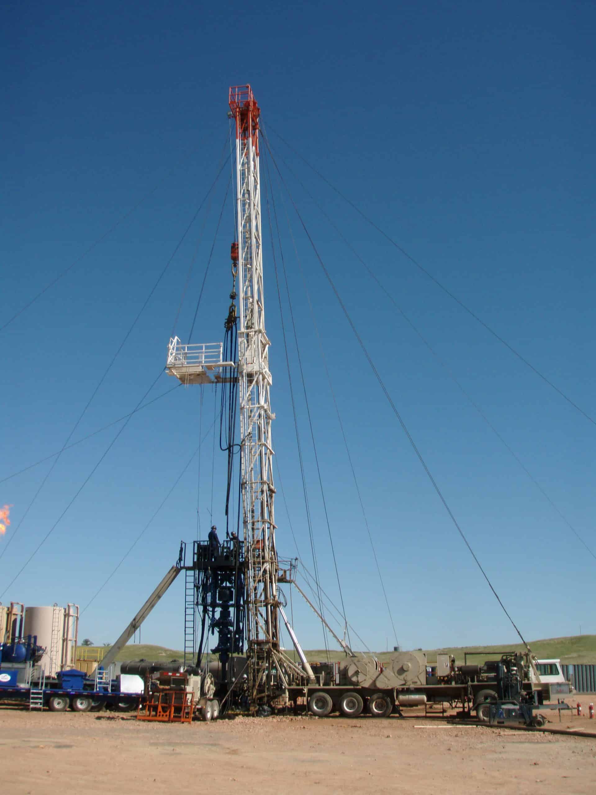
A drilling rig is an integrated system that drills wells, such as oil or water wells, in the earth"s subsurface. Drilling rigs can be massive structures housing equipment used to drill water wells, oil wells, or natural gas extraction wells, or they can be small enough to be moved manually by one person and such are called augers. Drilling rigs can sample subsurface mineral deposits, test rock, soil and groundwater physical properties, and also can be used to install sub-surface fabrications, such as underground utilities, instrumentation, tunnels or wells. Drilling rigs can be mobile equipment mounted on trucks, tracks or trailers, or more permanent land or marine-based structures (such as oil platforms, commonly called "offshore oil rigs" even if they don"t contain a drilling rig). The term "rig" therefore generally refers to the complex equipment that is used to penetrate the surface of the Earth"s crust.
Small to medium-sized drilling rigs are mobile, such as those used in mineral exploration drilling, blast-hole, water wells and environmental investigations. Larger rigs are capable of drilling through thousands of metres of the Earth"s crust, using large "mud pumps" to circulate drilling mud (slurry) through the drill bit and up the casing annulus, for cooling and removing the "cuttings" while a well is drilled. Hoists in the rig can lift hundreds of tons of pipe. Other equipment can force acid or sand into reservoirs to facilitate extraction of the oil or natural gas; and in remote locations there can be permanent living accommodation and catering for crews (which may be more than a hundred). Marine rigs may operate thousands of miles distant from the supply base with infrequent crew rotation or cycle.
Antique drilling rig now on display at Western History Museum in Lingle, Wyoming. It was used to drill many water wells in that area—many of those wells are still in use.
Until internal combustion engines were developed in the late 19th century, the main method for drilling rock was muscle power of man or animal. The technique of oil drilling through percussion or rotary drilling has its origins dating back to the ancient Chinese Han Dynasty in 100 BC, where percussion drilling was used to extract natural gas in the Sichuan province.Edwin Drake to drill Pennsylvania"s first oil well in 1859 using small steam engines to power the drilling process rather than by human muscle.Cable tool drilling was developed in ancient China and was used for drilling brine wells. The salt domes also held natural gas, which some wells produced and which was used for evaporation of the brine.
In the 1970s, outside of the oil and gas industry, roller bits using mud circulation were replaced by the first pneumatic reciprocating piston Reverse Circulation (RC) drills, and became essentially obsolete for most shallow drilling, and are now only used in certain situations where rocks preclude other methods. RC drilling proved much faster and more efficient, and continues to improve with better metallurgy, deriving harder, more durable bits, and compressors delivering higher air pressures at higher volumes, enabling deeper and faster penetration. Diamond drilling has remained essentially unchanged since its inception.
Oil and natural gas drilling rigs are used not only to identify geologic reservoirs, but also used to create holes that allow the extraction of oil or natural gas from those reservoirs. Primarily in onshore oil and gas fields once a well has been drilled, the drilling rig will be moved off of the well and a service rig (a smaller rig) that is purpose-built for completions will be moved on to the well to get the well on line.
Mining drilling rigs are used for two main purposes, exploration drilling which aims to identify the location and quality of a mineral, and production drilling, used in the production-cycle for mining. Drilling rigs used for rock blasting for surface mines vary in size dependent on the size of the hole desired, and is typically classified into smaller pre-split and larger production holes. Underground mining (hard rock) uses a variety of drill rigs dependent on the desired purpose, such as production, bolting, cabling, and tunnelling.
In early oil exploration, drilling rigs were semi-permanent in nature and the derricks were often built on site and left in place after the completion of the well. In more recent times drilling rigs are expensive custom-built machines that can be moved from well to well. Some light duty drilling rigs are like a mobile crane and are more usually used to drill water wells. Larger land rigs must be broken apart into sections and loads to move to a new place, a process which can often take weeks.
Small mobile drilling rigs are also used to drill or bore piles. Rigs can range from 100 short tons (91,000 kg) continuous flight auger (CFA) rigs to small air powered rigs used to drill holes in quarries, etc. These rigs use the same technology and equipment as the oil drilling rigs, just on a smaller scale.
The drilling mechanisms outlined below differ mechanically in terms of the machinery used, but also in terms of the method by which drill cuttings are removed from the cutting face of the drill and returned to surface.
An automated drill rig (ADR) is an automated full-sized walking land-based drill rig that drills long lateral sections in horizontal wells for the oil and gas industry.Athabasca oil sands. According to the "Oil Patch Daily News", "Each rig will generate 50,000 man-hours of work during the construction phase and upon completion, each operating rig will directly and indirectly employ more than 100 workers." Compared to conventional drilling rigs", Ensign, an international oilfield services contractor based in Calgary, Alberta, that makes ADRs claims that they are "safer to operate, have "enhanced controls intelligence," "reduced environmental footprint, quick mobility and advanced communications between field and office."steam assisted gravity drainage (SAGD) applications was mobilized by Deer Creek Energy Limited, a Calgary-based oilsands company.
Temple, Robert; Joseph Needham (1986). The Genius of China: 3000 years of science, discovery and invention. New York: Simon and Schuster. pp. 52–4
Baars, D.L.; Watney, W.L.; Steeples, D.W.; Brostuen, E.A (1989). Petroleum; a primer for Kansas (Educational Series, no. 7 ed.). Kansas Geological Survey. p. 40. Archived from the original on 8 November 2020. Retrieved 18 April 2011. After the cementing of the casing has been completed, the drilling rig, equipment, and materials are removed from the drill site. A smaller rig, known as a workover rig or completion rig, is moved over the well bore. The smaller rig is used for the remaining completion operations.
"Ensign Launches Newest And Most Powerful Automated ADR 1500S Pad Drill Rigs In Montney Play", New Tech Magazine, Calgary, Alberta, 21 November 2014, archived from the original on 10 December 2014, retrieved 6 December 2014
The term workover is used to refer to any kind of oil well intervention involving invasive techniques, such as wireline, coiled tubing or snubbing. More specifically, a workover refers to the expensive process of pulling and replacing completion or production hardware in order to extend the life of the well.
Workovers rank among the most complex, difficult and expensive types of wellwork. They are only performed if the completion of a well is terminally unsuitable for the job at hand. The production tubing may have become damaged due to operational factors like corrosion to the point where well integrity is threatened. Downhole components such as tubing, retrievable downhole safety valves, or electrical submersible pumps may have malfunctioned, needing replacement.
In other circumstances, the reason for a workover may not be that the completion itself is in a bad condition, but that changing reservoir conditions make the former completion unsuitable. For example, a high productivity well may have been completed with 5½" tubing to allow high flow rates (a narrower tubing would have unnecessarily choked the flow). Some years on, declining productivity means the reservoir can no longer support stable flow through this wide bore. This may lead to a workover to replace the 5½" tubing with 4½" tubing. The narrower bore makes for a more stable flow.
Before any workover, the well must first be killed. Since workovers are long planned in advance, there would be much time to plan the well kill and so the reverse circulation would be common. The intense nature of this operation often requires no less than the capabilities of a drilling rig.
The workover begins by killing the well then removing the wellhead and possibly the flow line, then installing a B.O.P commonly known as a blowout preventer, then lifting the tubing hanger from the casing head, thus beginning to pull the completion out of the well. The string will almost always be fixed in place by at least one production packer. If the packer is retrievable it can be released easily enough and pulled out with the completion string. If it is permanent, then it is common to cut the tubing just above it and pull out the upper portion of the string. If necessary, the packer and the tubing left in hole can be milled out, though more commonly, the new completion will make use of it by setting a new packer just above it and running new tubing down to the top of the old.
Although less exposed to wellbore fluids, casing strings too have been known to lose integrity. On occasion, it may be deemed economical to pull and replace it. Because casing strings are cemented in place, this is significantly more difficult and expensive than replacing the completion string. If in some instances the casing cannot be removed from the well, it may be necessary to sidetrack the offending area and recomplete, also an expensive process. For all but the most productive well, replacing casing would never be economical.

We like to throw around “blog ideas” over here at Croft to help my fellow blog partner, Amy and I have a new fresh blog every week. We try to keep our readers up to date with both the new and the old. Someone threw out the idea of writing about a workover rig. Still being new to the industry, I snatched this topic up because I simply wanted to learn more about it myself! My main focus for this blog is simply discussing what is a workover rig and why it is important.
First off, maybe you know a workover rig by a different name. They can be called completion wells or pulling units. I just want to try to avoid any confusion! I am going to give Wikipedia’s definition first and then break it down to layman’s terms for those of you who don’t quite understand what the Wiki is trying to say (Like me). According to Wikipedia, “The term workover is used to refer to any kind of oil well intervention involving invasive techniques, such as wireline, coiled tubing or snubbing. More specifically though, it will refer to the expensive process of pulling and replacing a completion.” Let’s break down some of that Terminology…
Coiled Tubing: A long metal pipe used to carry out operations similar to wirelining. However, it has the ability to pump chemicals through the pipe and push it downhole.
Snubbing: This method is used in more demanding situations when wireline and coiled tubing does not offer the strength and durability needed. Snubbing runs the bottom hole assembly on a pipe string using a hydraulic workover rig.
So basically, the purpose of a workover rig is to replace a well with a fresh completion. This may have to happen due to the well deteriorating or the changing of reservoir conditions. This is performed if a well completion is unsuitable for the job at hand. An example of the well deteriorating is the equipment may have become damaged or corroded such as production tubing, safety valves, electrical pumps, etc. An example of the changing of reservoir conditions maybe if the flow of a well has decreased over time. If this happens, when the well was originally drilled, it was fit for tubing that was big enough for a higher flow of oil and gas. As the flow decreased, smaller tubing is now needed.
For a workover to take place, a well must be killed or in other words, stop the flow of oil or gas. This is an intense procedure for a workover to take place, so they are planned long in advance.
n: a record made each day of the operations on a working drilling rig and, traditionally, phoned, faxed, emailed, or radioed in to the office of the drilling company and possibly the operator every morning.
(pronounced "tower") n: in areas where three eight-hour tours are worked, the shift of duty on a drilling rig that starts at or about daylight. Compare evening tour, morning (graveyard) tour.
(pronounced "tower") n: in areas where two 12-hour tours are worked, a period of 12 hours, usually during daylight, worked by a drilling or workover crew when equipment is being run around the clock.
n: the mass or weight of a substance per unit volume. For instance, the density of a drilling mud may be 10 pounds per gallon, 74.8 pounds/cubic foot, or 1,198.2 kilograms/cubic meter. Specific gravity, relative density, and API gravity are other units of density.
n: a special radioactivity log for open-hole surveying that responds to variations in the specific gravity of formations. It is a contact log (i.e., the logging tool is held against the wall of the hole). It emits neutrons and then measures the secondary gamma radiation that is scattered back to the detector in the instrument. The density log is an excellent porosity-measure device, especially for shaley sands. Some trade names are Formation Density Log, Gamma-Gamma Density Log, and Densilog.
n: a large load-bearing structure, usually of bolted construction. In drilling, the standard derrick has four legs standing at the corners of the substructure and reaching to the crown block. The substructure is an assembly of heavy beams used to elevate the derrick and provide space to install blowout preventers, casingheads, and so forth.
n: the crew member who handles the upper end of the drill string as it is being hoisted out of or lowered into the hole. On a drilling rig, he or she may be responsible for the circulating machinery and the conditioning of the drilling or workover fluid.
n: a removable, hard-steel, serrated piece that fits into the jaws of the tongs and firmly grips the body of the drill pipe, drill collars, or casing while the tongs are making up or breaking out the pipe.
n: a high-compression, internal-combustion engine used extensively for powering drilling rigs. In a diesel engine, air is drawn into the cylinders and compressed to very high pressures; ignition occurs as fuel is injected into the compressed and heated air. Combustion takes place within the cylinder above the piston, and expansion of the combustion products imparts power to the piston.
n: an oilwell-surveying method that determines the direction and angle of formation dip in relation to the borehole. It records data that permit computation of both the amount and direction of formation dip relative to the axis of the hole and thus provides information about the geologic structure of the formation. Also called dipmeter log or dip log.
n: 1. intentional deviation of a wellbore from the vertical. Although wellbores are normally drilled vertically, it is sometimes necessary or advantageous to drill at an angle from the vertical. Controlled directional drilling makes it possible to reach subsurface areas laterally remote from the point where the bit enters the earth.
n: in well cementing, the fluid, usually drilling mud or salt water, that is pumped into the well after the cement is pumped into it to force the cement out of the casing and into the annulus.
n: a source of natural reservoir energy in which the dissolved gas coming out of the oil expands to force the oil into the wellbore. Also called solution-gas drive. See reservoir drive mechanism.
n: a drilling tool made up in the drill string directly above the bit. It causes the bit to turn while the drill string remains fixed. It is used most often as a deflection tool in directional drilling, where it is made up between the bit and a bent sub (or, sometimes, the housing of the motor itself is bent). Two principal types of downhole motor are the positive-displacement motor and the downhole turbine motor.
adj: pertaining to packers and other tools left in the wellbore to be broken up later by the drill bit. Drillable equipment is made of cast iron, aluminum, plastic, or other soft, brittle material.
n: the employee normally in charge of a specific (tour) drilling or workover crew. The driller’s main duty is operation of the drilling and hoisting equipment, but this person may also be responsible for downhole condition of the well, operation of downhole tools, and pipe measurements.
n: an agreement made between a drilling company and an operating company to drill a well. It generally sets forth the obligation of each party, compensation, identification, method of drilling, depth to be drilled, and so on.
n: an internal-combustion engine used to power a drilling rig. These engines are used on a rotary rig and are usually fueled by diesel fuel, although liquefied petroleum gas, natural gas, and, very rarely, gasoline can also be used.
n: circulating fluid, one function of which is to lift cuttings out of the wellbore and to the surface. It also serves to cool the bit and to counteract downhole formation pressure.
n: all members in the assembly used for rotary drilling from the swivel to the bit, including the kelly, the drill pipe and tool joints, the drill collars, the stabilizers, and various specialty items. Compare drill string.
n: a method of formation testing. The basic drill stem test tool consists of a packer or packers, valves or ports that may be opened and closed from the surface, and two or more pressure-recording devices. The tool is lowered on the drill string to the zone to be tested. The packer or packers are set to isolate the zone from the drilling fluid column.
n: the column, or string, of drill pipe with attached tool joints that transmits fluid and rotational power from the kelly to the drill collars and the bit. Often, the term is loosely applied to include both drill pipe and drill collars.
n: a type of portable service or workover rig that is self-propelled, using power from the hoisting engines. The driver"s cab and steering wheel are mounted on the same end as the mast support; thus the unit can be driven straight ahead to reach the wellhead.
n: a single well that produces from two separate formations at the same time. Production from each zone is segregated by running two tubing strings with packers inside the single string of production casing, or by running one tubing string with a packer through one zone while the other is produced through the annulus. In a miniaturized dual completion, two separate casing strings are run and cemented in the same wellbore.
Download Workover & Drilling Rig Inspection Checklist As we mentioned in the Rig Audit Article, rig inspection is an important process that shall be done from time to time. Especially, after the rig moving to a new drilling location.

Social media is cool. I’m able to keep up with people in the industry, all over the world. The different methods and equipment make for some interesting conversations. I got into a discussion the other night about derrick design, the different rigs and the reasons for the designs, so I thought I’d share a little of what I’ve learned over the years.
Derricks in the drilling industry basically come in two types: internally loaded and externally loaded. Examples of externally loaded derricks would include a standard Smeal rig or an oilfield workover rig. This means that the load is dispersed to the foundation by transmitting and dividing it on the block to the load on guy wires, or hydraulic cylinders. This design is very handy, as it allows you to rig up over most any hole and allows plenty of working room. Guy wires can be either to the ground or back to the rig itself. Most smaller rigs use guys to the front of the unit, and any ground wires are just for wind stability. Pulling power is often limited by the weight of the unit. I’m sure you have seen or heard about situations that lifted the front wheels off the ground. That’s pretty much the limit, and it’s hard on equipment. Downsides include flex and overall capacity. They will flex and move as loads are increased. These derricks can be built very strong, but the engineering challenges get larger on the big units.
Very common in all classes of the drilling industry are internally loaded derricks. Everyone is familiar with Mayhew, Gardner-Denver and Failing rigs, as well as many others. This includes the biggest oilfield rigs. The rotary, and the load, are inside the derrick. Forces are transmitted directly from the block to the foundation, without external guys or support. These derricks are typically vertical and are self-stabilizing, and don’t require any headache or ground wires. This makes for a very strong and compact unit, but sacrifices working room on smaller rigs.
A well-designed derrick will last a lifetime of daily use — and occasional abuse. Since they are over our heads, we should know, understand and maintain our derricks.
Older designs, such as cable tool rigs, are externally loaded, but have such a tried-and-true design that they’re able to handle most of the loads put on them. Eventually, rotary rigs came along and were internally loaded derricks. These are very strong derricks for their size, which is a good thing. On most water well rigs, the drawworks don’t have enough power to damage the derrick. Whether this is a design feature or an economic consideration, it sure is safer. I’ve seen drillers who would ignore the weight indicator (if they had one) and just “give ‘er hell.” With most water well rigs, they run out of clutches or horsepower before they have a train wreck. Oilfield rigs are different. They have the power to do anything the rig will take, and more. That’s why they have weight indicators and crews are trained to use them. When these derricks take a load, several things happen. They will almost always “squat” with a significant load. This can be anything from half an inch to several inches, depending on load, foundation and design. But they usually stay over the hole. In my years as a borehole fisherman, I have been on many stuck pipe jobs. This generally requires that I pull more weight than the rig sees on a day-to-day basis. Sometimes, the company has strict rules but, sometimes, it is up to the people on the rig as to what their iron will stand. It’s not uncommon to pull way over the rated capacity. When I have to do this, I always look very carefully at everything. As I said, when you load a conventional derrick, it will squat when it takes the load. It will also twist a little, but stay over the hole. However, as you increase the load, most derricks will twist a little more in proportion to the load. When the load is released, the derrick will spring back to its original size and shape. This is normal elasticity. At some point, though, as you increase the load, the derrick will not continue to flex or twist. This is the danger zone, and indicates that you have reached the limits of elasticity of the steel. Been there, done that. It’s not pretty. It’s then time to try a different approach.
Usually, a well-designed derrick will last a lifetime of daily use — and occasional abuse. Since they are over our heads, we should know, understand and maintain our derricks. If you crater a derrick — and live through it — you will have a lot of explaining to do.
Newer rigs are built either way, commonly with box tubing and an external load. These are great rigs and very popular. But, while they allow more working room, they do take more maintenance. I guess it’s what you grew up with and what you are used to.
The following is a list of seasonal work gear worn by drilling rig workers. Savanna supplies rig employees with coveralls, hard hat, safety glasses & impact gloves (1 pair).
Drilling rig crews are generally made up of six (6) people: Rig Manager, Driller, Derrickhand, Motorhand, Floorhand, and Leasehand. Each crew works 12 hours shifts as the rig operates 24 hours per day, and each position is vital to the operation of the rig.
Work in the oil and gas services industry is seasonal. Because of the weight of rigs and their equipment, and the remote location of wells, these locations are often only accessible when the ground conditions can tolerate heavy loads. Therefore, wells are typically drilled and serviced in the winter when the ground is frozen solid, or in the summer, when the ground has thawed and dried sufficiently. During the spring and fall, when the ground is in a transitional state, it is too soft to move equipment on and easily damaged. For this reason, provincial governments implement “road bans” prohibiting heavy loads from operating in certain areas. During this time, rig work is slower, and many rigs are shut down and their crews sent home. Be prepared to be off for anywhere from 6 to 12 weeks without pay during this time. However, rigs that are shut down are usually in need of maintenance, and there may be opportunities for employees who would like to help in this regard. Employees may be eligible for Employment Insurance benefits during seasonal shutdowns.
To work on a drilling rig, you must be able to get to and from all of your work locations. As drilling often occurs in remote areas, having reliable transportation is considered mandatory for non-camp locations. Drilling rigs commonly operate 24 hours per day, 7 days per week with either three crews working 8 hour shifts or two crews working 12-hour shifts. Most often day crews and night crews will alternate weekly, so each crew has a chance to work during both the day and night. Most crews will work 14 days straight with 7 days off in-between. The typical living situation while working falls into three categories: Non-Camp, Full Camp and Texas Camp.
Non-Camp: When the rig site is near a town, non-camp conditions normally apply. Crews will stay in hotel rooms and receive a per day living allowance for food and accommodation. The living allowance is paid out on your pay cheque based on days worked, therefore you will need to be able to pay for your food and accommodation out of your own pocket.
Full-Camp: When a rig site is in a remote location, crews may stay in a full camp. In a full-camp all food and full accommodation is provided. Once at the camp, the crew travels to and from the rig in the crew truck. Almost all camp work is available in the winter only.
Texas Camp: These camps are typically located nearby the rig location. Crews are responsible for supplying their own bedding, cooking supplies, groceries and toiletries. While staying at a texas camp, a daily allowance is provided for food and toiletries. The living allowance is paid out on your pay cheque based on days worked, therefore you will need to be able to pay for your food and toiletries out of your own pocket.
Savanna employees are paid every two weeks via direct bank deposit. Savanna’s compensation package includes company group health, dental and disability coverage including paramedical coverage (acupuncturist, chiropractor, massage therapist, naturopath physiotherapist and much more). Savanna also offers a competitive and rewarding retirement savings plan.
Once you have completed your orientation, you will immediately receive any other necessary training. This involves Workplace Hazardous Materials Information System (WHMIS) and Transportation of Dangerous Goods (TDG), along with an in-depth General Safety Orientation. This training is mandatory and provided by Savanna at no cost to the employee. Job-related, hands on training is conducted in the field through Savanna’s Rig Mentoring Program.
Some well locations have sour gas (Hydrogen Sulfide or H2S) present which is extremely dangerous. All employees are required to possess a valid H2S Alive certificate regardless of whether they are working on a sour gas well. This can be obtained by signing up for and completing a one-day (8 hour) course.
Courses are available at various locations across the province. For more information, contact Energy Safety (formerly Enform) at (780) 955-7770 or visit www.enform.ca or Leduc Safety Service at (780) 955 3300 or visit www.leducsafety.com. The cost of the course is usually between $130 and $150 plus tax, and the certification is valid for three years.
While it is not mandatory to have this certification, each service rig crew is required to have two members who are certified in Standard First Aid with CPR level C. Therefore, obtaining a certification beforehand is a great way to improve your chances of being hired.
Savanna is committed to providing a safe, productive and respectful work environment. As such, Savanna has Policies in place to ensure the protection of our employees, contractors, the pubic and the environment. All Savanna employees are required to acknowledge and follow the policies at all times.

The American Petroleum Institute has released the fourth edition of Recommended Practice 54 (RP 54), Occupational Safety and Health for Oil and Gas Well Drilling and Servicing Operations, which provides procedures for promoting and maintaining safe and healthy working conditions for personnel in drilling and well servicing operations.
The document applies to rotary drilling rigs, well servicing rigs, and special services as they relate to operations on location. First published in 1981, significant revisions in this edition of Recommended Practice 54 include a new section on flowback operations which is key for safe well testing, revised requirements for facility and site process hazard assessment and mitigation, and introduction of formal risk assessments as well as expanded provisions for offshore operations.

This website is using a security service to protect itself from online attacks. The action you just performed triggered the security solution. There are several actions that could trigger this block including submitting a certain word or phrase, a SQL command or malformed data.

The claimed invention relates generally to well drilling and servicing equipment, and more specifically to portable rigs for handling pipe strings when making up and disconnecting long strings of pipe used in a bore hole during operations that are carried out in the exploration and production of petroleum and other fluids and minerals from substantial depths below the earth"s surface.
Production wells must be worked over from time-to-time due to either faulty downhole equipment or to some unusual or adverse well condition. For example, if the production string is damaged or leaking, it may be necessary to pull the tubing from the casing and replace it with new string. In a gas lift installation, the gas lift valves may not be in good working condition, and it therefore may be necessary to run exchange gas lift valves into the well. When tubing becomes plugged with sand, it is necessary to insert a tool such as a macaroni work string into the pipe to ream out or flush out the material clogging the flow of oil through the pipe. Other remedial service operations include gravel packs, fishing jobs, plug backs, recompletion requiring pulling and reinstallation of production tubing, drill-out of cement plugs, running sand screens and sand packing.
When such service operations become necessary, a portable installation called a workover rig is brought to the well site and set up. Generally, these rigs consist of a derrick or mast which supports pulleys or block and tackle arrangements that are operable to pull the pipe string from the well. These prior art workover rigs are usually heavy and difficult to erect and further often have the limited operational capability of only being able to hoist or pull pipe from a well without the capability of snubbing or pushing pipe back into the well. Since these conventional workover rigs cannot develop a downward force to push a string of pipe into the well, in such operations the well must necessarily always be under control or "dead", as is known in the art. This may require a preparatory operation of injecting a suitable substance such as mud or "kill" fluid into the well to maintain sufficient column weight of fluid to resist the pressure within the well which is tending to force the tubing out. However, it is usually desirable to carry out the workover operations without resorting to the injection of "kill" fluid into the well since the well may be lost if the formation is damaged because of the presence of the workover "kill" fluid. In such "killing" workover operations, there is a very high risk that the productivity of the subsurface formation may decline so severely after killing the well that the well must be abandoned.
An overriding concern in the construction of workover rigs is to get the necessary equipment into and out of the well as rapidly and safely as is economically possible. This concern has led to the development of a portable well service rig having a transportable mast or derrick. Before the invention of the first portable well service unit, it was necessary to leave the drilling derrick in place over the well for use in future well service operations. The portable well service rig eliminated the need for a permanent derrick and thus materially reduced overall well service costs. The early portable rigs, however, were unloaded in a heap and later sorted out, and then assembled without any definite plans therefore consuming a substantial amount of time in rigging up. Even when unitized and transported on pallets, a significant amount of time was required for transporting, rigging up and dismantling the palletized equipment. In the palletized approach, the field assembly and erection of the mast, mast support structure and reeving of the hoist cable caused expensive but unavoidable delays. Therefore recent improvements to conventional portable workover rigs have focused on changes which simplify the operations of transporting, rigging up and dismantling.
One of the problems associated with the development of the portable workover rig is that of providing sufficient working space below the mast floor while limiting the mast and its supporting base to dimensions which permit its transportation across public highways. A working space must be provided below the mast floor in order that the mast can be supported vertically above and engage well head equipment which may extend as much as eight to ten feet above the elevation of the rig platform deck. The minimum height of the mast is determined primarily by the length of the sections of pipe string added to or removed from the pipe already in the well bore. However, if the mast is so high that its length and height clearance when in a horizontal position on the workover rig exceeds the limits allowed by the state, the mast must be at least partially disassembled or must be telescoped. Most wells have tubing sections which are in the range of thirty-six to forty feet long, so that the construction of a transportable mast assembly having a stroke for accomodating the removal or insertion of such tubing sections poses no problem insofar as complying with state highway regulations.
As mentioned above, the conventional practice has been to provide a mast having telescoping sections or having sections which must be separately assembled and erected on site. To provide ample clearance for the well head equipment, the mast floor has been elevated above the ground level by placing it on a mast substructure carried by the rig base platform. This substructure is normally fabricated of heavy structural steel in a massive weldment which must be separately transported. The loads it must bear are greater than those born by the mast, since the substructure must support not only the weight of the derrick with its pipe string load, but other loads, such as the rotary table and draw works as well. However, the length and height of the separate mast support base when combined with the reclining mast may in some cases exceed highway limits, so that separate transportation, field assembly and erection are required. Most conventional rigs provide separate support base and mast sections which may be unbolted and separately transported to provide the short lengths allowed for highway travel. However, additional rigging up and tear down time is required for such arrangements.
Other important considerations involved in the construction of portable workover rigs are the strength and stability of the mast. The mast must be constructed to safely carry all loads which will ever be used in the well over which it is placed. This is the collapse resistance caused by vertical loading, or the dead load capacity of the mast. The largest dead load which will be imposed on the derrick will normally be the heaviest string of production tubing run in the well. However, this heaviest string of tubing will not be the greatest strain placed on the mast. The maximum vertical load which will ever be imposed on the mast will probably be the result of pulling on equipment, such as drill pipe or casing, that has become stuck in the hole. Therefore it must be considered that, sometime during the useful life of the mast, severe vertical strain will be placed on it because the equipment has become stuck in the hole. Therefore the mast and its intermediate support platform must be constructed to withstand and react loads which will exceed the capacity of the hoist line which will be used on the rig.
The mast must be also designed to withstand the maximum wind loads to which it will be subjected. The horizontal force of the wind acting on the mast and production tubing is usually counteracted by using from one to three guy wires along each leg of the mast which are attached to "dead man" anchors located some distance from the mast. A "dead man" anchor is made from a short length of large pipe, a concrete block, or a short section of timber, which is buried in the ground to provide an anchor for the guy wire. A substantial amount of time and labor is expended in setting up the "dead man" support lines. Additionally, when carrying out workover operations off shore, there is no practical way to anchor the guy lines. A suitable structural alternative for the guy wire supports is necessary for reacting the wind loads, and the snubbing forces must also be reacted in order to drive production tubing into an offshore well against the downhole pressures which may be encountered. Therefore there is a continuing interest in improving the design of support substructure for free-standing masts which do not require guy wires for support.
As a result of the many improvements to portable workover rigs, such vehicles now transport practically all the necessary servicing equipment directly to the field locations and when servicing has been completed, remove the necessary equipment to another well in need of service in the same field or in a different field miles away. Thus the equipment necessary to service a number of wells each having different service requirements has been greatly reduced, and consequently the labor and cost, as well as the amount of equipment has correspondingly dropped. However, there still remains considerable interest in the provision of more efficient and simplified machines in order that the job of well servicing in general may be carried out efficiently and at reasonable cost.
It is, therefore, the principal object of the present invention to provide an improved general purpose workover rig having a unitized configuration which is transportable across public highways and which can be easily rigged up and dismantled in the field.
An important object of the invention is the provision of a mast assembly which is transportable on a base platform having a mast and a mast support substructure which can be separately collapsed for transport in a low profile, reclining position over the base platform to comply with the length and height limitations established for public highways, and which are erectable to an elevated operating position overlying well head equipment.
Yet another object of the invention is the provision of a transportable mast assembly having a base support substructure for supporting the mast in freestanding relation for withstanding wind loading without the use of dead man anchor lines.
Still another object of the invention is the provision of a workover rig having a mast, a mast support substructure, and draw works in which the static load of the draw works is supported by a portable base platform member rather than by being supported by the intermediate mast support substructure.
Another object of the invention is the provision of an erectable mast support substructure which cooperates with a portable base platform for stabilizing a free-standing mast erected on the support substructure and reacting vertically directed snubbing forces without the use of dead man anchor lines.
Yet another object of the invention is the provision of a workover rig having draw works carried by a portable platform and a mast and mast support substructure which are separately movable from a reclining transport position to an erect operating position wherein erection and retraction of the mast and mast support assembly can be carried out without disturbing cable reeving on the mast or on the draw works.
An important object of the present invention is the provision of draw works for a workover rig which can be carried in a reclining position on a portable rig platform and which is operably connected to develop driving forces required for either hoisting or snubbing operations.
Still another object of the invention is the provision of a portable workover rig having a mast and mast support substructure which are separately movable from a reclining transport position over a portable base platform to an erect workover position overlying well head equipment lying either above or below the elevation of the portable base platform.
Yet another object of the invention is the provision of a base support substructure for an erectable mast and a carriage assembly for moving the base support substructure from a reclining transport position over a portable base platform to an erect workover position, the carriage assembly cooperatively coupled to the base platform for stabilizing the erectable mast in free-standing relation on the mast support substructure and for transmitting mast load reaction forces through the portable base platform.
Another object of the invention is the provision of a workover rig having an erectable mast supported on a cantilever support substructure which is movable from a reclining transport position overlying a portable base platform to an elevated position of use wherein the cantilever support base is extended beyond the portable base platform for carrying out workover operations.
Still another object of the invention is the provision of a vertically adjustable stack assembly for accomodating the varying elevations of existing well head flange connections and which further serves to transfer the weight of a mast from an intermediate support structure to the well casing and for simultaneously anchoring a portable base platform to the well head casing, thereby further stabilizing the mast support substructure.
A related object is the provision of a bolster assembly for attachment to the vertically adjustable stack assembly for providing lateral support for a length of pipe string extending between the mast and the well head equipment to prevent buckling of the length of pipe string when it is undergoing compression loading during either snubbing or drilling operations.
Finally, it is an important object of the present invention to provide a powered drill sub assembly for carrying out drilling operations in combination with a transportable mast assembly which includes a vertically yieldable stab assembly interconnecting a powered drill sub to a traveling block thereby permitting vertical displacement of the power sub relative to the traveling block during tubing make-up and break-out operations while reacting torque forces which are produced by such operations.
The foregoing objects are achieved by a workover rig which is mounted on a portable base platform such as a skid or the bed of a trailer vehicle, and which features a collapsible mast assembly which is movable from a reclining transport position to an erect elevated position of use. The mast assembly is supported for freestanding operation by a carriage assembly including a cantilever substructure support base mounted on the rig support platform for pivotable movement from the reclining transport position to an elevated position of use. The carriage assembly includes lift arms coupled in parallel relation intermediate the cantilever support structure and the rig support platform, thereby defining a parallelogram throughout the range of movement of the mast support assembly for maintaining the cantilever support base in parallel alignment with the base platform. According to this arrangement, the mast and the carriage assembly are separately collapsible for transport in a low profile, reclining position over the base platform to comply with the length and height limitations established for public highways. The mast and the carriage assembly are separately erectable to an elevated operating position overlying well head equipment which may be disposed at an elevation either above or below the elevation of the portable base platform. The mast is connected in hinged engagement with the carriage assembly, and both the carriage assembly and the mast are separately driven from the transport position to the erect operating position by linear hydraulic actuators. The linear hydraulic actuators in combination with the carriage assembly serve to stabilize the mast for free-standing operation and transmit mast load reaction forces through the portable base platform. An important feature of this arrangement is the cantilever support substructure which is extended to an elevated operating position beyond the portable base platform for carrying out workover operations adjacent elevated well head equipment. A further advantage of this arrangement is that the mast, mast support substructure, and draw works can be carried in a collapsed, low profile transport position and both erection and retraction of the mast and mast support assembly can be carried out without disturbing the cable reeving on the mast and draw works.
According to an important aspect of the invention, the workover rig is provided with a mast, a mast support substructure, and draw works in which the static load of the draw works is supported by a portable base platform member rather than being supported by the intermediate mast support substructure. In this arrangement, the draw works includes a linear hydraulic actuator having rod and housing elements in which one of the elements is anchored to the base platform with the other element being mounted for movement along the base platform through a stroke pathway which extends transversely with respect to the mast. The traveling sheaves are cooperatively reeved with hoist and snub cables for developing driving forces required for either hoisting or snubbing operations. The advantage of this arrangement is that the intermediate mast support substructure must support only the mast in an erect operating position with the substantial weight of the draw works being supported by the portable base platform. This arrangement permits the mast support substructure to be easily movable from the reclining, low profile transport position to the elevated workover position without the burden of the draw works. Hoisting and snubbing operations are carried out by the draw works which includes a linear hydraulic actuator carried on the base platform, a load engaging traveling block supported for vertical movement along the mast by hoist and snub cables, and by traveling sheaves carried by the actuator through a stroke pathway which is oriented transversely with respect to the mast. In this arrangement the load engaging traveling block is driven upwardly or downwardly along the mast in response to extension and retraction of the rod and housing elements of the hydraulic actuator.
In yet another important embodiment of the invention, a vertically adjustable stack assembly is provided for accomodating the existing elevation of well head flange connections. The vertically adjustable stack assembly includes an adjustable support column assembly anchoring the rig platform to the well head casing, and an adjustable support column assembly interposed between the well head casing and the mast for transferring the weight of the mast from the intermediate mast support structure to the well casing. The vertically adjustable stack assembly simultaneously anchors the portable base platform to the well head casing, thereby stabilizing the mast support substructure, while relieving the burden of the mast from the intermediate mast support substructure. This arrangement helps stabilize the mast for free-standing operation on the mast support substructure and for transmitting mast load reaction forces through the portable base platform, thereby eliminating the need of dead man anchor lines which would otherwise be required for stabilizing the mast and for reacting dynamic mast loads.
According to another important embodiment of the invention, a bolster assembly is attached to the adjustable stack connector assembly for providing lateral support to a length of pipe string extending between the mast and the well head flange. In a preferred embodiment, the bolster assembly includes a number of bolster plates each having central openings for receiving the length of pipe string with link elements interconnected in a scissors arrangement on opposite sides of the bolster plates for permitting accordion-like movement of the bolster plates relative to each other in parallel, stacked relation and with their central openings concentrically aligned. The bolster plates are fastened to the adjustable stack connector and provide lateral support to the length of pipe string extending between the mast and well head equipment to prevent buckling of the length of the pipe string when it is undergoing compression loading during either snubbing or drilling operations.
Finally, the portable workover rig of the invention is adapted to perform drilling operations by the combination of a vertically yieldable stab assembly which interconnects a powered drill sub with a traveling block for permitting vertical displacement of the powered drill sub during make-up and break-out operations while simultaneously reacting torque forces which arise in response to rotary forces applied to the drill string. The vertically yieldable stab assembly includes upstanding stab receptacles anchored to the top side of the traveling block and stab elements downwardly depending from the under side of the powered drill assembly for engagement with the stab receptacles. Each stab element is supported for vertical reciprocal movement between retracted and extended positions, and each stab element is yieldably biased to the fully extended position, thereby permitting vertical displacement of the power sub relative to the traveling block during the make-up and break-out operations while reacting torque forces which are produced by operation of the powered drill sub.
The foregoing and other related objects and advantages of the present invention will become more apparent from the following specification, claims and appended drawings wherein:
FIG. 3 is a top plan view of the workover rig of FIG. 1 with the mast and carriage assembly removed which illustrates the layout of the draw works and related equipment on the deck of a portable rig support platform;


 8613371530291