
difference between drilling rig and workover rig quotation
We like to throw around “blog ideas” over here at Croft to help my fellow blog partner, Amy and I have a new fresh blog every week. We try to keep our readers up to date with both the new and the old. Someone threw out the idea of writing about a workover rig. Still being new to the industry, I snatched this topic up because I simply wanted to learn more about it myself! My main focus for this blog is simply discussing what is a workover rig and why it is important.
First off, maybe you know a workover rig by a different name. They can be called completion wells or pulling units. I just want to try to avoid any confusion! I am going to give Wikipedia’s definition first and then break it down to layman’s terms for those of you who don’t quite understand what the Wiki is trying to say (Like me). According to Wikipedia, “The term workover is used to refer to any kind of oil well intervention involving invasive techniques, such as wireline, coiled tubing or snubbing. More specifically though, it will refer to the expensive process of pulling and replacing a completion.” Let’s break down some of that Terminology…
Coiled Tubing: A long metal pipe used to carry out operations similar to wirelining. However, it has the ability to pump chemicals through the pipe and push it downhole.
Snubbing: This method is used in more demanding situations when wireline and coiled tubing does not offer the strength and durability needed. Snubbing runs the bottom hole assembly on a pipe string using a hydraulic workover rig.
So basically, the purpose of a workover rig is to replace a well with a fresh completion. This may have to happen due to the well deteriorating or the changing of reservoir conditions. This is performed if a well completion is unsuitable for the job at hand. An example of the well deteriorating is the equipment may have become damaged or corroded such as production tubing, safety valves, electrical pumps, etc. An example of the changing of reservoir conditions maybe if the flow of a well has decreased over time. If this happens, when the well was originally drilled, it was fit for tubing that was big enough for a higher flow of oil and gas. As the flow decreased, smaller tubing is now needed.
For a workover to take place, a well must be killed or in other words, stop the flow of oil or gas. This is an intense procedure for a workover to take place, so they are planned long in advance.
Drilling calls for complex, carefully engineered equipment — and inevitably this equipment can wear down over time and require replacement. That’s where a workover rig comes in. Workovers are among the most expensive and complicated tasks in the drilling industry, so here are a few things you should understand about them.
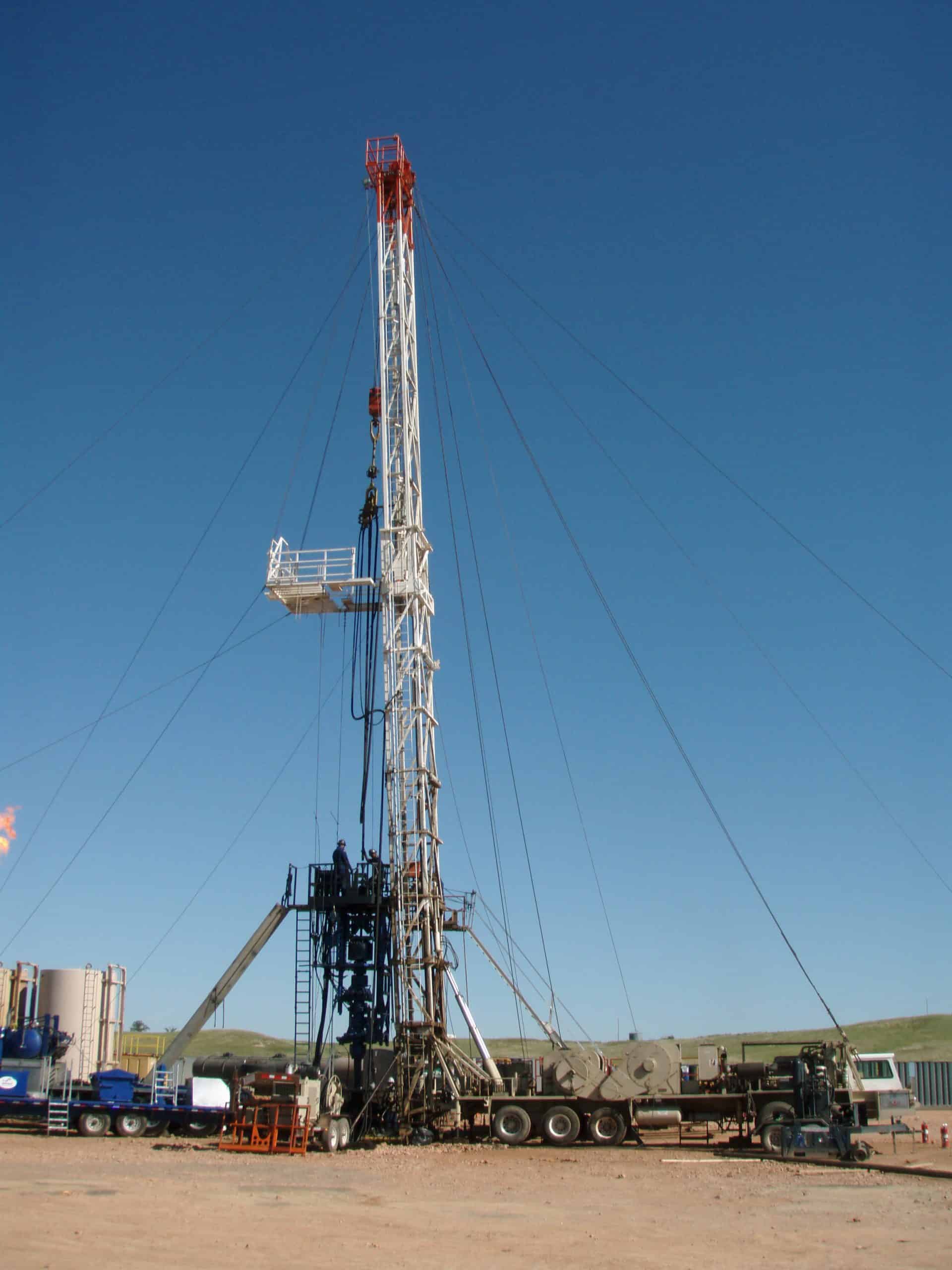
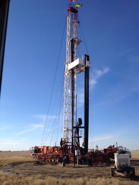
A workover is a complex maintenance task that involves pulling completion hardware out of a well in order to extend the life of the well. A workover rig is a specially designed rig that makes it easier to take out or insert tubing into a well.
To complete a well servicing, the well is first killed. This halts the flow of fluids in the reservoir. The wellhead and flow line will then be removed and the completion hardware will begin to be pulled out of the well using the workover rig. Replacement parts will then be lowered into the hole accordingly.
Because workovers are involved in time-consuming processes, through-tubing workovers might be initiated, which can occur without forcing teams to kill a well and do a full well servicing. This might be considered first before deciding on a full well servicing.
A workover rig is needed when a well is no longer suitable for the drilling job it was originally built for. Maybe the production tubing has incurred damage over time or downhole tubing has stopped functioning correctly. Or perhaps the contents of the reservoir that the tubing is drawing from has changed and requires adjusted tubular components. In any case, the well is unable to perform efficiently and could even compromise the safety of those working on the well. At that point, its components must be replaced and a workover rig must be constructed.
You always want your well to perform to expectations. Katch Kan can help thanks to our zero-spill installation system, which ensures your well servicing operations will proceed safely and efficiently. We offer a wide array of well servicing solutions, which are designed to prevent fluid spills, keep workers safe, lower clean-up costs and reduce operation time.
The term workover is used to refer to any kind of oil well intervention involving invasive techniques, such as wireline, coiled tubing or snubbing. More specifically, a workover refers to the expensive process of pulling and replacing completion or production hardware in order to extend the life of the well.
Workovers rank among the most complex, difficult and expensive types of wellwork. They are only performed if the completion of a well is terminally unsuitable for the job at hand. The production tubing may have become damaged due to operational factors like corrosion to the point where well integrity is threatened. Downhole components such as tubing, retrievable downhole safety valves, or electrical submersible pumps may have malfunctioned, needing replacement.
In other circumstances, the reason for a workover may not be that the completion itself is in a bad condition, but that changing reservoir conditions make the former completion unsuitable. For example, a high productivity well may have been completed with 5½" tubing to allow high flow rates (a narrower tubing would have unnecessarily choked the flow). Some years on, declining productivity means the reservoir can no longer support stable flow through this wide bore. This may lead to a workover to replace the 5½" tubing with 4½" tubing. The narrower bore makes for a more stable flow.
Before any workover, the well must first be killed. Since workovers are long planned in advance, there would be much time to plan the well kill and so the reverse circulation would be common. The intense nature of this operation often requires no less than the capabilities of a drilling rig.
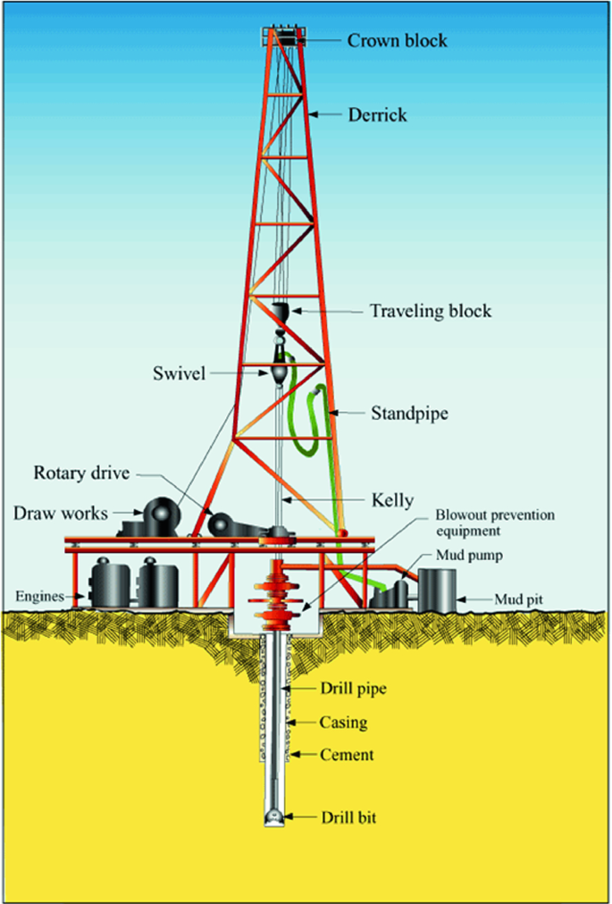
The workover begins by killing the well then removing the wellhead and possibly the flow line, then installing a B.O.P commonly known as a blowout preventer, then lifting the tubing hanger from the casing head, thus beginning to pull the completion out of the well. The string will almost always be fixed in place by at least one production packer. If the packer is retrievable it can be released easily enough and pulled out with the completion string. If it is permanent, then it is common to cut the tubing just above it and pull out the upper portion of the string. If necessary, the packer and the tubing left in hole can be milled out, though more commonly, the new completion will make use of it by setting a new packer just above it and running new tubing down to the top of the old.
Although less exposed to wellbore fluids, casing strings too have been known to lose integrity. On occasion, it may be deemed economical to pull and replace it. Because casing strings are cemented in place, this is significantly more difficult and expensive than replacing the completion string. If in some instances the casing cannot be removed from the well, it may be necessary to sidetrack the offending area and recomplete, also an expensive process. For all but the most productive well, replacing casing would never be economical.
The design of drilling rigs for the petroleum industry has remained basically unchanged for the last four decades. Today"s offshore rigs have evolved from the basic land rig concept towed offshore in the 1950"s. Factors such as deeper waters and harsher environments have increased demands for additional auxiliary equipment such as active crown mounted motion compensator, topdrive and comprehensive mechanised pipehandling equipment. Implementation additional equipment and new systems have followed an "add-on" philosophy which has resulted in concepts of monstrosity. Further development to meet today"s and future demands of versatility, such as integration of capabilities for snubbing and coiled tubing operations, will probably evolve to a stage where the "multi-functional" course could turn to the "multi-useless" curse.
A thorough review of the status, combined with the desire to be able to contribute with more optimal solutions, have lead Maritime Hydraulics to the development of the RamRig concept.
Main Objectives. Maritime Hydraulics launched the idea in 1987, whereafter a joint venture engineering study with British Petroleum Development Norway Ltd. was carried out in 1988 and 1989. The study evaluated all known rig concepts with emphasise on the aspects of hoisting and tubular handling efficiency. The main objectives of the development work were:Improve safety by reduced manning and improving working environments,
The study concluded the RamRig concept to be the most optimal of the alternatives considered. However, as it was found to be too bold and radical for its time, it was decided that the project was to be shelved. This was mainly due to the lack of field experience of important components like the control system and the large hydrostatic transmission required.
After about 5 years Saga Petroleum"s efficient exploration, "EfEx", study, re-vitalised the concept in 1994. The detailed design of a complete drilling rig for an application for deepwater exploration operations was completed by June 1995. In this study the RamRig was found to be an important enabler for developing more efficient total concepts.

The market for mobile offshore drilling units has changed over the two last years. In general the activity level is higher, with utilisation of floating drilling units close to 100 %. The reason for this increased activity level is mainly due to the following elements :Increased number of production wells to be drilled by floating rigs, for sub-sea field developments.
The drilling rig technology has basically been more or less identical over the last twenty or thirty years, except for the implementation of the top drive system in the early eighties. Challenging technical requirements for exploring and exploiting harsh environments areas have motivated the industry to search for new solutions. New technology and ideas are implemented both for the type of vessel and for the drilling rig. The RamRig as presented at OTC 96 (1) is one of the contributors to the new technology.
This paper outlines differences between the RamRig (RR) and the conventional drawworks based rig (DWBR). Improvements are specifically for the following topics:Hoisting and compensating system
The coming year four units based on the RR technology will be operative, and MH have defined further development programmes that will complete the RR and further improve its performance compared to conventional rigs. Two of these products are :Power slip joint, PSJ (2), for making the conventional riser tensioning system obsolete.
The DWBR was developed early this century and as technical requirements have increased, all new developments have been added to the existing concept. The basic rig was also used when the industry went offshore and initial compensation was executed by means of bumper subs. Later on in-line drill string compensator, top mounted compensator and active heave compensator have been developed and added to the DWBR. (ref. fig. 1 Draw works based rig main functions). Further requirements for top-drive and mechanized pipe handling have also been adopted without any changes to the base concept.
For control of the equipment and the entire rig, advancedcomputer control systems have been implemented. In addition, for controlling components related to each other regarding working envelope, zone management systems are required. All these systems built into the existing rig has made it more costly to maintain and less optimized for safety and working environment.
Another problem area for operations is handling and stacking of the BOP and X-mas trees. On many rigs the layout is not suitable for the size and number of modules to be handled.

With the increase in world energy needs for fossil fuels, exploration and production of hydrocarbons have been extended to remote areas such as offshore locations. Although the main intended purpose of a drilling rig and its main systems may not be influenced by well location, the water depth requires modification of land rigs. Consequently, mobile offshore drilling units (MODUs or rigs) or marine rigs were developed and introduced. The main design features for offshore rigs are portability and maximum water depth of operation. Offshore rigs are classified broadly as floating or bottom support. The floating rigs are categorized as semisubmersible, and drillship. Bottom supported rigs are categorized as barge, jackup, and platform rigs [3].
These types of rigs are used for drilling at shallow water depths. The operational water depth of these submersible barge rigs is less than 40 (ft) and where there is no severe wave action. The rig is installed on a barge, large pontoon-like structure, and towed to the location. When on location, the pontoons are filled with water, the platform sinks partly or fully, and rests on its anchors. When the drilling operation is completed, water is pumped out and the platform is ready to move to a new location. If the barge rests on the seafloor, then it is counted as a bottom supported drilling rig.
Semisubmersible (see Fig. 5.3) rigs are capable of performing drilling operations while resting on the seafloor as well as being in a floating position. In other words, the drilling rig is on a barge similar to submersible rigs. Compared to submersible rigs (known also as bottle-type semisubmersible rig), the semisubmersible rigs (known as column-stabilized semisubmersible rigs) are designed with good stability and seakeeping characteristics. These types of rigs are usually used at larger water depths where a rig cannot rest on the seafloor. When the semisubmersible rig cannot rest on the seafloor, the unit is either anchored onto the position or kept on location with dynamic positioning systems. The construction and operational cost of semisubmersible rigs are higher than for submersible rigs.
A drillship is a type of floating vessel where the drilling rig is mounted on a merchant ship (see Fig. 5.4). The drillship is usually used for offshore exploration and equipped with advanced dynamic positioning systems. As drillships benefit from the dynamic positioning systems, they are usually much more costly compared to semisubmersible rigs. In recent years, drillships have been used for operation in deepwater and ultra-deepwater areas. There are some generations of drillships, which are equipped with only mooring systems or general dynamic positioning systems that have lower cost compared to semisubmersible rigs. Another challenge for using a drillship is its susceptibility to severe waves, wind and currents. A benefit of using drillships is their efficient mobilization and high speed between drilling locations.
Recently, riserless well intervention vessels have been used for small activities such as coring [4]. These types of vessels are small sized drillships which have the capability to be equipped with well intervention equipment such as coiled tubing units. The cost of these vessels is much lower than cost of other types of rigs; however, time spent waiting on weather is higher compared to other types of drilling rigs. The vessels will be reviewed later in this chapter.
Jackups are the most common bottom-supported rigs. The rig consists of a barge-type hull (triangular barge form) and three legs, Fig. 5.5. When the rig is in place, legs are lowered to adjust to a given clearance. Jackups are self-contained rigs that can be mobilized and demobilized easily. Depending on their size, they can operate in water depths up to 500 (ft) [5].
Platform rigs are usually employed during development phase where an economically viable offshore field is exploited. Many directional wells can be drilled from a platform. Large platforms are capable of accommodating drilling rigs or modular rigs and therefore are known as self-contained (see Fig. 5.6). Rig-up time of platform rigs are usually less compared to most of the MODUs as no mooring system nor dynamic positioning system is required. But there are some circumstances when the rig-up time can increase due to waiting on weather.
There are circumstances where the platform is small and not capable of accommodating all the components of a drilling rig or storage facilities. In this situation, a floating vessel is anchored next to the platform (see Fig. 5.7). The floating vessel is known as the rig tender. The rig tender can contain storage facilities, many of the rig components and the living quarters.
Vessels are small sized merchant ships which offer some basic operations such as well intervention activities and anchor handling. Compared to drillships, the day rate of vessels are much lower. These types of vessels are categorized as light well intervention vessel and anchor handing vessels.
Light Well Intervention Vessels (LWIVs) have been used for over 25 years in the North Sea. LWIVs are typically monohull, flexible and extremely cost efficient and can be used for a single or multi-well (a campaign) of subsea wells. They can accommodate a wireline unit and coiled tubing unit, Fig. 5.8.
Well integrity and suspension operations including mechanical plug setting, mechanical repair or well maintenance, perforating and setting cement plugs, wellhead cutting and removal, logging, Remotely Operating Vehicle (ROV) services, and pumping operations are typical activities which are conducted by use of LWIVs [6]. The future approach for the use of LWIVs is to perform the complete permanent P&A operations. However, there are some limitations to be solved before reaching to the goal, see Table 5.1.
Anchor handling operations may contribute 10–20% of the total well costs of offshore exploration drilling [8]. In a conventional anchor handling operation, the rig’s winches are used to tension the anchors. AHV transports and deploys the anchors, connects the required chains, wires and polyester ropes. AHV can pre-lay the anchors before the rig arrives, and more time can be dedicated to drilling or P&A operations.
/cloudfront-us-east-2.images.arcpublishing.com/reuters/XMYRPMRVYVIVFDQ3B63SKJODDY.jpg)
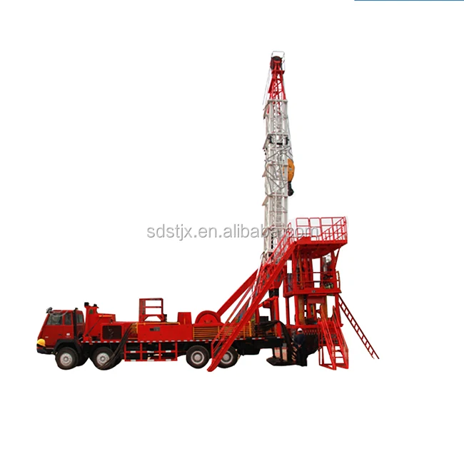
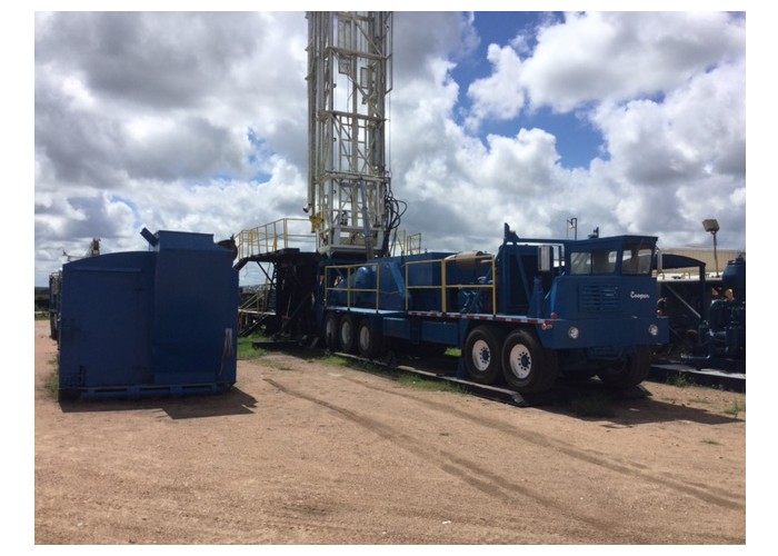
Workover Rig is available for both onshore as well as offshore Workover purposes at affordable prices. There are a number of companies that manufacture the Workover Rig as well as Rig packages that are required for different kinds of drilling jobs and meet the standards that have been set by the American Petroleum Institute or the API. The Rig packages are shipped worldwide. The rigs are included other than the simple Workover and they include the following:
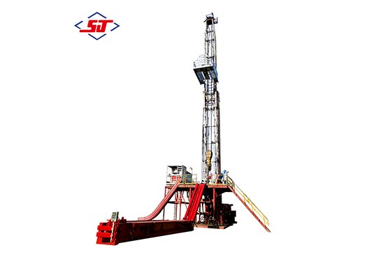
Workover Rig is known as the Workover the different types of rigs include the offshore and onshore Rig that range from 150 horsepower to 1000 horsepower. Workover rigs have a surface depth that is equipped with diesel engines and transmissions and is available from 8000 ft to 30000 ft. Workover rigs contain a full line of drilling packages. Rig takes into account the skid mounted drilling rigs and the ones that are trailer mounted. Workover skid mounted drilling rigs incorporate the diesel-electric AC/VFD or the DC/SCR drive rigs, mechanical drive rigs and the combination drive Rig that ranges from 1000 horsepower to 6000 horsepower; while the trailer mounted Rig ranges from 450 horsepower to 1000 horsepower.
A lot of Workover Rig uses the double telescopic mast with the help of a single mast and is operated by wide wheel base axels, high strength steel beam, low cross section tires, dual pipeline brakes as well as hydraulic assist steering for the Workover. Rig mast is a double section type and uses a telescopic mast for dual safety protection. The gear shift and throttle of the engine can be remote controlled.
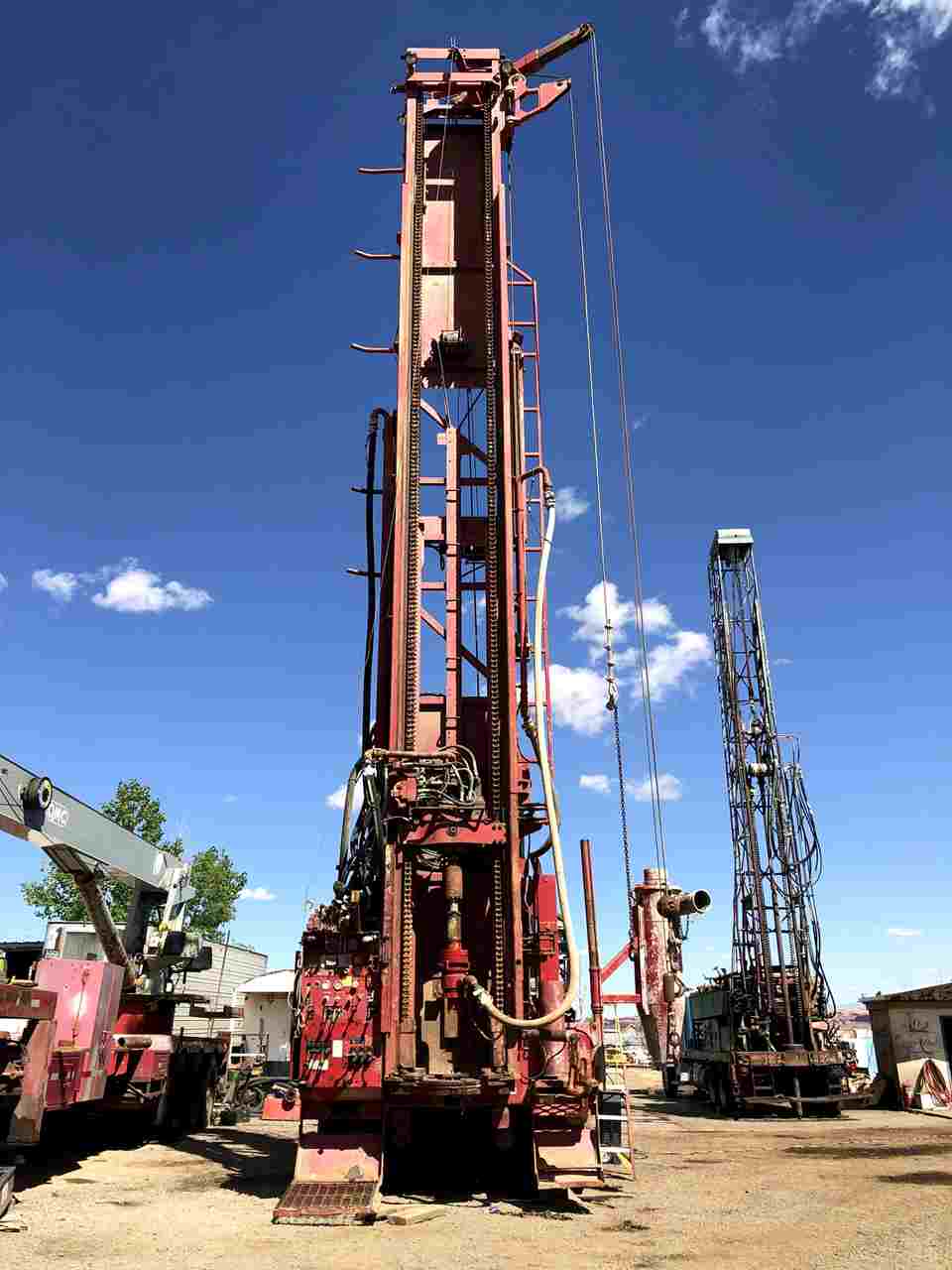
Workover types of Rig are available in the form of the single drum as well as the double drum. The groove ensures the alignment of in place as well as for long life. The optional Workover accessories for the auxiliary brakes include air thrust disc type clutch, brakes for the braking of the main drum, forced water circulating cooling with the brake rims as well as the optional brakes. Workover rigs are centrally controlled with electricity. The other kinds of drilling equipment include drilling equipment, triplex mud pumps, well control equipment; solids control equipment, oil control tubular goods and quality equipment. Work over rigs run casing tools and clean outs inside and outside a hole already drilled.
The American Petroleum Institute has released the fourth edition of Recommended Practice 54 (RP 54), Occupational Safety and Health for Oil and Gas Well Drilling and Servicing Operations, which provides procedures for promoting and maintaining safe and healthy working conditions for personnel in drilling and well servicing operations.
The document applies to rotary drilling rigs, well servicing rigs, and special services as they relate to operations on location. First published in 1981, significant revisions in this edition of Recommended Practice 54 include a new section on flowback operations which is key for safe well testing, revised requirements for facility and site process hazard assessment and mitigation, and introduction of formal risk assessments as well as expanded provisions for offshore operations.

This website is using a security service to protect itself from online attacks. The action you just performed triggered the security solution. There are several actions that could trigger this block including submitting a certain word or phrase, a SQL command or malformed data.
This website is using a security service to protect itself from online attacks. The action you just performed triggered the security solution. There are several actions that could trigger this block including submitting a certain word or phrase, a SQL command or malformed data.

For most operators, improving profitability on their wells is an ongoing battle between getting the right equipment, making the job easier, and keeping a strict eye on the bottom line.
However, a common issue in our industry is that often operators don’t use fit-for-purpose equipment for the job at hand. While standard equipment may seem like the less expensive option, it ends up costing operators a lot more in the long run.
A perfect example of this is that many operators go with a full-size drilling rig for surface interval drilling because it is more convenient. Often, they are already engaged with the service provider and the equipment is already on site — so it seems like this is the most cost-effective decision. In the end, though, operators end up paying more in fuel and personnel costs, and increasing their HSE risks, with this option.
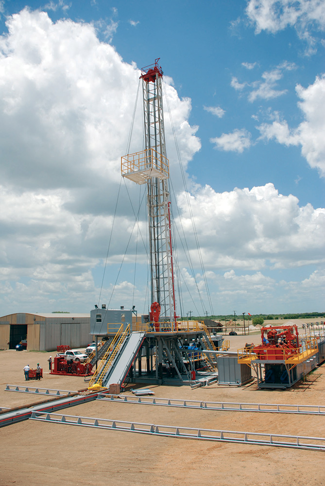
Full-size rigs are made for constructing wells with total depths over 20,000 feet. These are enormous machines for enormous jobs. As a result, they have an enormous footprint in terms of costs and risks. When drilling surface intervals and running surface casing, a full-size rig is not the right equipment for the job. While it may seem more effective at the time, a surface drilling rig or spudder rig is the better choice.
Less fuel consumption and lower fuel costs: Surface drilling rigs are highly engineered for surface drilling and running surface casing. They are smaller in size as compared to full-size rigs, which means they use a lot less fuel. To be exact, spudder rigs actually burn up to 50% less diesel compared to full-size rigs, which means they also cost about 50% less to operate.
Equipment optimization:When operators use full-size rigs for surface drilling and running surface casing, they aren’t able to reserve the machines for their intended use. If operators have a separate spudder rig, then the full-size rigs can be used for applications better suited for them, reducing overall operating costs.
Lower personnel costs: Typically, a full-size rig requires a crew of 16 people to operate, while a top hole rig only has a crew of nine. With a lower personnel count, there are lower payroll costs. Not only that, the costs for personnel transportation are lower as well, in addition to the HSE risks.
Safer work environment: With a full-size rig, operators must switch between mud systems, which means that the crew has to mix different muds on location. Handling more fluids increases the chances of spills, which is detrimental to the environment and to the crew. A top hole drilling rig uses a closed-loop mud system, so there is no need to switch between different mud systems or handle different types of mud on location.
A smaller, fit-for-purpose preset surface drilling rig is a more economical choice than a full-size rig when it comes to drilling surface intervals and running preset surface casing.
A differentiating factor between EnerCorp’s surface drilling rigs and our competitors is the customized casing running tools (CRT) that enable us to be faster and more cost effective than other service providers.
Fit-for-purpose equipment: Our CRT’s are specifically designed for our RD20 XC rigs. This allows for the casing to be torqued up to proper torque specs per the casing manufacturer’s specifications.
Efficient operations: The CRT allows for casing to be pumped through while running in the well bore. Running casing full of fluid is more efficient at keeping the well bore full and circulated. Pumping through the casing also allows for cuttings to be evacuated from the bottom of the hole for less restriction. This keeps the well bore open and clear.
Lower safety risks:Our CRT’s eliminate the need for a swedge, which is used to fill casing in standard practice, as well as the man basket to make up the swedge. This considerably reduces the safety risk for the crew on site.
Better processes:Competitors use alternative methods to run casing: Wishbone style casing elevators. In this process, a tool is used to run casing on our competitors rigs that does not keep the casing full and requires a swedge to be rigged up to fill it. There is far greater exposure and risk to the man in the basket on a board suspended from the derrick. Plus, dry casing run with this method is far less efficient because each joint needs to be filled via the swedge on top of the casing, taking more time. The Wishbone is a far more dangerous method as sometimes it does not latch correctly and can cause the casing to be unsettled during the run.
Less personnel:We don’t use a third-party casing crew as having extra people on location significantly increases the overall footprint and safety risk involved during the execution of the job. Plus, call out times and wait times can be long, costing the operator a lot of extra money.
When working with EnerCorp, operators not only get the benefits of using a surface drilling rig, but also the additional advantages of using fit-for-purpose equipment that is highly optimized as compared to competitor options.
The U.S. oil industry is reaching some of its highest production levels in history. It’s no surprise that American oil and gas companies added 4.5 billion barrels of crude oil and lease condensate proved reserves in 2012 — a 15.4% increase from 2011 and the largest year-over-year increase since 1970. These days, the oil and gas industry helps supply 9.8 million jobs, and there are enough oil reserves on hand to meet at least another 53.3 years of production.
One of the most key pieces of oil drilling rig systems is the rig substructure. The first step in setting up a drill rig, setting up the rig substructure involves unloading equipment and moving it to the location where it will remain during drilling. From there, personnel must assemble, weld and level the various pieces of equipment. During this process, personnel can become injured due to a number of hazards that exist.
Are your personnel being as safe as they should be while setting up the drill rig substructure? To improve the safety of your oil drilling equipment, be sure to follow these three impossible-to-ignore tips:
First and foremost, all personnel must be properly trained in safety procedures and job hazards for setting up the rig substructure. Whether the training takes place during pre-job safety meetings or during JSA briefings, no one should be working on your drilling rig systems without undergoing safety training first.
When setting up the rig substructure, personnel should be wearing protective equipment like eye and face protection for welding, long-sleeved clothing and more. Welding, in particular, can be very dangerous work. Ensure that your workers never look directly into a welding flame.
Another potential hazard is slips, trips and falls, especially when workers are working on an elevated surface. Require all personnel to wear fall protection while working from heights and to keep debris off the ground to prevent tripping and falling.
The College of Earth and Mineral Sciences is committed to making its websites accessible to all users, and welcomes comments or suggestions on access improvements. Please send comments or suggestions on accessibility to the site editor. The site editor may also be contacted with questions or comments about this Open Educational Resource.
The College of Earth and Mineral Sciences is committed to making its websites accessible to all users, and welcomes comments or suggestions on access improvements. Please send comments or suggestions on accessibility to the site editor. The site editor may also be contacted with questions or comments about this course.
Plan the Well: As we have discussed, exploration well prospects are generated by exploration geologists; while development wells locations and objectives are generated by development geologists. Once the surface locations and well objectives are known, the geologists work with the drilling engineers to develop the detail drilling proposals. In addition, all permits (environmental, safety, regulatory, etc.) are acquired during the final stages of the planning process when a solid well proposal is developed.
Perform Shallow Gas Survey: To ensure there are no shallow gas hazards which may result in a kick or blow out, a shallow gas survey is performed to identify the locations and depths of any potential shallow gas hazards. Preliminary surface locations and well trajectories may be altered from the original well proposal to avoid these shallow gas hazards.
Prepare the Wellsite: The site preparation involves building clearing land for use by the rig, building access roads to the well site or well pad, construct infrastructure for water, water disposal, and electricity, dig and line all mud pits to prevent ground water or water table contamination, dig reserve pits for cutting storage (for eventual disposal), and drill the holes which will eventually become the rat hole and the mousehole. The site preparation may involve multiple contractors and companies to perform all of the required work. As we discussed in earlier lessons, a lot of site-preparation time and the environmental footprint can be minimized if multi-well pads are used in the field development.
Set the Conductor Casing: Prior to the arrival of the drilling rig, an Auger Unit (in hard rock regions) will drill a large diameter hole capable of accommodating 18 in. to 36 in. conductor casing (see Figure 9.16). In soft rock regions or at offshore locations, a diesel hammer may be used to hammer the conductor casing into place. The conduct casing may go to depths of 40 to 300 ft depending on the location. The conductor casing is typically set through the top soil and loose rocks to the bed rock. The objective of the conductor casing is to isolate the wellbore from the top soil to ensure that loose debris does not enter the well during early drilling operations. The conductor casing is then cemented into place.
Move-In and Rig Up (MIRU): Once the wellsite is prepared and the conductor casing is in-place, the rig is brought on location. Most land rigs, particularly those in North America, are transported on multiple trucks. Once on the well site or well pad, the rigging-up process begins. Rigging up the well consists of taking the rig modules from the trucks and assembling the rig. Included in the rigging up process is setting-up all of the rig systems and testing these systems. Here is a YouTube video, "Rigging up Land Drilling Rig" (3:35), showing the Rigging Up process of the derrick:
Transporting and assembling the rig may take 50-75 workers (two crews), 35 – 40 vehicles, and take up to four days. If a multi-well pad is used, once the rig is rigged-up for the first well, then the rig can simply be skidded over to the next location without having to dig-down.
Spud the Well: After the rig has been inspected and all of the systems tested the well can be Spudded. Spudding a Well refers to starting the rotary drilling operations for that well.
Drill Down to the Surface Casing Depth: The first section of the well to be drilled is the section that goes down to the pre-determined surface casing depth (Casing Point). Obviously, for this section of the wellbore, the drill bit diameter must be smaller than the ID (inner diameter) of the conductor casing. In this shallow section of the wellbore, fresh water aquifers (both for personal and municipal use) exist. As discussed earlier, shallow gas hazards may also exit. The objectives of drilling this first section of the well is to allow the setting and cementing of the surface casing to:
This section of the well is drilled through the most environmentally sensitive depths. Consequently, when this section of the hole is drilled, it is typically drilled with the most environmentally friendly drilling fluid (possibly either air or fresh water) and cased and cemented as soon as possible to alleviate any potential of contaminating fresh water aquifers. By running the surface casing string, we are putting the environmentally sensitive water table behind pipe and protecting it from future well (drilling and production) activities.
Run and Cement the Surface Casing: Once the surface casing point is reached, the surface casing is run into the wellbore and cemented into place. This process is performed by:
Cementing is a common activity planned and implemented by drilling engineers, and you will learn a lot more of the details in your future drilling courses. The following YouTube video, "Running Casing" (7:01), shows the cementing process (note: this is a commercial video for Frank’s International):
Continue this Process to Drill to the Next Casing Point: This drilling process is continued to the next pre-determined casing point. The selection of these intermediate-string casing points is beyond the scope of the class, but the criteria are based on the mud weight, the Fracture Pressure of the formations to be drilled (the pressure that causes the formation to fracture), the locations of any Lost Circulation Zones, and the locations of any High Pressure Zones. As we discussed earlier, any of these situations may result in a kick and a potential blowout. The objectives of the intermediate casing strings are:
Continue this Process to Drill to each Casing Point: This process is repeated for each of the planned casing points. Obviously, as successive casing strings are run and cemented into place, smaller diameter tools and drill bits must be used for continued drilling operations. As we discussed earlier, the two most important drilling parameters within the Driller’s control to maximize the Rate of Penetration (ROP) of the drill bit are the weight-on-bit and the rotational speed of the rotary system in Revolutions per Minute (RPM).
Continue this Process to Drill to Total Depth (TD): Once the final intermediate casing string is run and cemented, the drilling process is continued until the well reaches the TD (Total Depth) of the well. At this point, the well is said to be TD’ed.
Log the Well with Open-Hole Logs: At this point, the sand face is exposed to the well and Open-Hole Logging Tools can be run in the well. Open-hole logs are used to measure certain properties of the subsurface formation that are of interest to the geologists and engineers working on the well and the reservoir.
Run and Cement the Production Casing String or Liner: If a production casing string or production liner is to be used in the completion, then they are run and cemented at this time.


 8613371530291