
hydraulic workover rig free sample
Download Workover & Drilling Rig Inspection Checklist As we mentioned in the Rig Audit Article, rig inspection is an important process that shall be done from time to time. Especially, after the rig moving to a new drilling location.
This website is using a security service to protect itself from online attacks. The action you just performed triggered the security solution. There are several actions that could trigger this block including submitting a certain word or phrase, a SQL command or malformed data.
Enjoy the best returns on your investment with these supreme hydraulic workover rig ranges at Alibaba.com. Their efficacy and reliability will prove that they’re worth their price tags. They will empower you to attain your mining and drilling goals and definitely surpass your expectations.
The hydraulic workover rig you’ll come across at Alibaba.com are designed with the operators’ safety and comfort in mind. Advanced safety precautions such as perfect ergonomics for physical comfort, reduced noise, low dust emissions, and minimal physical hazards are notable features of the hydraulic workover rig. Operating these hydraulic workover rig is not very complicated. They have many standard features and professionally trained operators will have an easy time working with them.
Get wholesale hydraulic workover rig from global wholesalers, Alibaba. At competitive prices, you can maintain, modify, enhance or replace your machines and vehicles. From the selection of new, used, and rebuilt parts from different manufacturers, choose the suitable hydraulic workingover rig to get your construction equipment up and running in no time. The collection of hydraulic worksover rig at Alibaba.com includes parts for both mechanical and electrical systems. From transmission systems to hydraulics, engines to pumps, and brakes to wheels, Al Alibaba.com got it. You can chat with your supplier to make modifications or even get custom designs, and that’s what Alibcom. for your business needs.

The rig assist unit was installed on top of the rig’s Bops. A landing joint was lowered into the stack and screwed into the tubing hanger. The snubbing Bops were tested using the rig pump to 35mpa

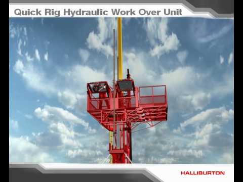
Base Station: Located at ground level and normally mounted in a doghouse or data cab, our base station incorporates four CPU panels/receivers that house the control system software. The system communicates through a Class 1 Division 2 router to all of the wireless sensors (transducers, proximity sensors and pressure sensors). The wireless devices are used to monitor the operation of the hydraulic workover unit, snubbing unit or rig. The basket-mounted touch screen station is a slave station that replicates the base station display. This is a wireless connection to the control center that operates on a web server for ease of access

The global hydraulic workover unit market size is predicted to grow at a 3.84% CAGR in the forecast period (2020- 2027), states the current Market Research Future (MRFR) report. A hydraulic workover unit is the perfect well intervention solution for re-entry operations, well interventions, and well maintenance. This unit uses hydraulic cylinders for lifting the tubular or out of the well. The hydraulic cylinders enable complete control over tubular movements and helps in eliminating the need for a huge mast construction that is present on conventional drilling rigs.
According to the MRFR report, there are numerous factors that are propelling the global hydraulic workover unit market share. Some of these entail technological advances in oil and gas well production, increasing offshore production post decline in oil prices, the burgeoning need for hydraulic workover units in the offshore oil and gas industry, the rising electricity demand, increasing focus on offshore exploration, the production of E&P of oil and gas, the rising efforts by upstream companies to improve the production from the mature fields, and the increasing oil and gas production. The additional factors adding to the global hydraulic workover unit market value includes the growing development of natural gas resources, the rising focus on mature oil and gas fields with the implementation of digital technologies which are the latest hydraulic workover unit market trends, rising energy demand in developing economies, increasing number of exploration activities, well drilling activities, and hydraulic fracturing, growing demand for snubbing services, and rising number of mature oil and gas fields.
On the contrary, stringent environmental regulations, lack of skilled workforce, problems related to the use of hydraulic workover unit like long rig-up time, and problems in transport for its heavy weight may impede the global hydraulic workover unit market revenue over the forecast period.
The oil and gas sector unfortunately has faced the brunt of the ongoing COVID-19 crisis which in turn has impacted the hydraulic workover unit market. Owing to the present scenario, several oil and gas companies across regions were compelled to shut down their services and producing assets as countries practiced complete or partial lockdown strategy for dealing with the pandemic. Across the region, companies has either delayed or suspended the key oil and gas projects. Besides, the crisis has also impacted the rig count for oil and gas, well drilling and production activities, and also crude oil prices. All these factors have negatively impacted the global hydraulic workover unit market growth.
The MRFR report highlights an inclusive analysis of the global hydraulic workover unit industry based on application, installation, service, and capacity.
By capacity, the global hydraulic workover unit market is segmented into above 150 tonnes, 50 to 150 tonnes, and up to 50 tonnes. Of these, the above 150 tonnes capacity segment will lead the market over the forecast period.
By service, the global hydraulic workover unit market is segmented into snubbing and workover. Of these, the workover service segment will dominate the market over the forecast period.
By installation, the global hydraulic workover unit market is segmented into trail mount and skid mount. Of these, the trail mount installation segment will spearhead the market over the forecast period.
By application, the global hydraulic worker unit market is segmented into offshore and onshore. Of these, the onshore application segment will have the lions share in the market over the forecast period.
Geographically, the global hydraulic workover unit market is bifurcated into Europe, North America, South America, the Asia Pacific, & the Middle East and Africa (MEA). Of these, North America will have the lions share in the market over the forecast period. Per capita consumption, production, and exploration of oil and gas, advances in upstream operations, high production of crude oil produced from tight oil resources in the US, the rise in the production and extraction of oil and gas increases the need for hydraulic workover units to perform routine well maintenance for offshore installations, inland waters, and land, increase in the need for cost-efficient method to repair leading to the installation of hydraulic workover units, the growth in unconventional resources in Canada and the US, and the demand for intervention operations in the maturing offshore fields in the Gulf of Mexico and other onshore fields in the US are adding to the global hydraulic workover unit market growth in the region.
In Europe, the global hydraulic workover unit market is predicted to hold the second-largest share over the forecast period for technological advances and increasing exploration and production of oil and gas.
In the APAC region, the global hydraulic workover unit market is predicted to have admirable growth over the forecast period. Rise in demand for energy in emerging economies of India and China are adding to the global hydraulic workover unit market growth in the region.
In the MEA and South America, the global hydraulic workover unit market is predicted to have sound growth over the forecast period. The presence of large untapped energy reserves is adding to the global hydraulic workover unit market growth in the region.
The prominent players profiled in the global hydraulic workover unit market report include ZYT Petroleum Equipment Co., Ltd (China), Uzma Berhad (Malaysia), PT Elnusa Tbk (Indonesia), Canadian Energy Equipment Manufacturing FZE (UAE), Velesto Energy (Malaysia), Superior Energy Services (US), Basic Energy Services (US), High Arctic Energy Services Inc. (Canada), Precision Drilling Corporation (Canada), Cudd Energy Services (US), Archer (Norway), National Oilwell Varco (US), and Halliburton (US), among others.
The global hydraulic workover unit market is fragmented and also competitive with the presence of many domestic as well as international industry players. They have incorporated assorted strategies to stay at the forefront and also cater to the surging needs of the customers, including collaborations, partnerships, contracts, geographic expansions, new product launches, joint ventures, and more. Additionally, these players are also making heavy investments in research and development activities for strengthening their portfolios and also creating a hold in the market.

Sets hydraulic jacks, handles pads/boards and assists in attaching the guy wires to the anchor. We are currently looking for Experienced & Entry level…
Mechanical skills should include, but are not limited to, mechanical, electrical, pneumatic and hydraulic troubleshooting and repair of trucks, cranes and…
Sets hydraulic jacks, handles pads/boards and assists in attaching the guy wires to the anchor. We are currently looking for Experienced & Entry level…
Manages tools on the workover rig floor and assists in daily maintenance. Must have a minimum of 1 year of experience as a workover rig floorhand to be…
Manages tools on the workover rig floor and assists in daily maintenance. Must have a minimum of 1 year of experience as a workover rig floorhand to be…
Demonstrated work experience with hydraulic systems. Demonstrated work experience with hydraulic systems. Demonstrated work experience with hydraulic systems.
Sets hydraulic jacks, handles pads/boards and assists in attaching the guy wires to the anchor. Minimum (1) year of Derrick hand experience required; at least…
Understand the rig’s hydraulic, pneumatic, and electrical systems. Perform all required equipment inspections-workover rig, fall arrest system, derrick,…
Sets hydraulic jacks, handles pads/boards and assists in attaching the guy wires to the anchor. Key offers Medical, Vision, Dental, and Life Insurance, short…
Sets hydraulic jacks, handles pads/boards and assists in attaching the guy wires to the anchor. Key offers Medical, Vision, Dental, and Life Insurance, short…
Sets hydraulic jacks, handles pads/boards and assists in attaching the guy wires to the anchor. The Floor Hand position is part of a 4-5 person workover rig…
Sets hydraulic jacks, handles pads/boards and assists in the attaching the guy wires to the anchor. Performs all well-servicing tasks from an elevated position…
Sets hydraulic jacks, handles pads/boards and assists in attaching the guy wires to the anchor. Key offers Medical, Vision, Dental, and Life Insurance, short…
Sets hydraulic jacks, handles pads/boards and assists in attaching the guy wires to the anchor. The Floor Hand position is part of a 4-5 person Plug &…
Ø Minimum one-year experience of workover rig experience. Set hydraulic jacks, handles pads/boards and assists in attaching the guy wires. Ø First Aid/CPR/AED.
Set hydraulic jacks, pads, and guy-out. Currently accepting applications for experienced Workover Rig crew members including floor hands, derrick hands and…
2+ years hydraulic jet pump or experience with triplex or PD pumps preferred. The Service Tech will be responsible for the installation of downhole jet pump…
The global hydraulic workover unit (HWU) market size was USD 8.11 billion in 2020. The market is anticipated to grow from USD 8.59 billion in 2021 to USD 13.21 billion in 2028 at a CAGR of 6.4% in the 2021-2028 period. The global impact of COVID-19 has been unrivaled and staggering, with it witnessing a negative demand across all regions amid the pandemic. Based on our analysis, the global hydraulic workover unit (HWU) market exhibited a decline of -14.5% in 2020 compared to the average year-on-year growth during 2017-2019. The growth during the forecast period is attributable to this market"s demand and growth, returning to pre-pandemic levels once the epidemic is over.
The COVID-19 pandemic initiated by the spread of the novel coronavirus has had a damaging impact on the global industrial landscape. This industry faced significant losses and have had to reduce operations due to the imposition of rigorous lockdowns to contain the spread of the COVID-19 virus. Consequently, the outbreak of the virus has transformed the demand for HWUs.
As the hydraulic workover unit industry is majorly dependent on oil and gas activities, the decline in oil prices in a long time has significantly impacted the investment in the instrument. The imposition of lockdowns in various countries and the shutting down businesses except for essential services with minimal workforce affected the energy demand. This factor has directly impacted work in the well interventions sector.
The world is likely to derive massive oil and gas from offshore production. The more arduous production conditions in offshore locations increase the investment in more complex and newer technologies like hydraulic workover units. The onerous requirement for offshore with ease of operations is the primary market driver during the projected period.
There is a substantial increase in demand for developing a safe, versatile, and cost-effective tool for workover and well intervention operations due to the increasing number of mature oil fields. This factor bolsters the demand for HWUs globally. This equipment can be efficiently used with low setup times and are more cost-effective. Earlier workover rigs were used for similar operations, which took a lot of time and effort to be set up and used. Further, the wells had to be killed before operations, However, with newer technologies, HWUs with snubbing capabilities have made snubbing capabilities possible with newer technologies.
In 2021, MEIL, India started manufacturing a new type of HWUs with indigenous know-how, especially for the local market. The increasing demand for more effortless functioning, avoiding well-killing, secure and cost-effective well intervention units is an important trend for the hydraulic workover unit market.
A mature oil and gas field is past peak production. These oilfields account for a majority of the world"s crude oil production. With enhanced technological approaches like enhanced oil recovery (EOR), the recovery of mature oil fields has seen a tremendous increase. Increasing recovery from mature fields has necessitated prolonging the well and improving production using well interventions and workover.
With the deterioration in oil reserves, companies have increased their focus on inventing equipment required to access remaining reserves on mature wells. The prime focus is to improve recovery and prolong life. But the amplified water cut with constrained topside facilities, growing flow assurance problems, rising operating costs, and integrity issues because of the maturing facilities have made brownfield operationally and economically impractical. The increasing requirement for workover services is anticipated to bolster the market growth.
The growing population explosion and urbanization has resulted in a spike in energy requirement from the various end-user sector. As renewable energy is still in an early adoption stage of its product life cycle, the majority of power generation is handled by hydrocarbons. Due to inadequate development of other energy sources, the growing global oil and gas demand enhances well drilling and maintenance. The increase in crude oil and shale gas production capacities and an increasing number of brownfields is expected to enhance the well workover and intervention demand, fueling the market growth.
The primary factor restraining the hydraulic workover unit market growth is the consumer shift towards clean fuels. The increasing requirement of the renewable energy sector will undoubtedly decrease the investment being made in the oil and gas energy sector, which will harm the well intervention sector. The increasing proportion of power generation using renewable energy can hinder the principal investments being made for oil and gas. Also, the necessity to reduce carbon emissions has powered the acceptance of renewable energy, with government incentives being granted worldwide. Further, the developing competence of renewables for power generation with durable benefits can result in increased adoption over conventional fuels.
The services carried out by hydraulic workover units are completions, plug & abandonment, ESP completion, sand screen installations, well deepening, fishing/clean-outs, casing repairs, etc. Workover segment includes operations over dead-wells, while snubbing involves installing or removing pipes in or out of live wells. The increasing demand for dead wells" services due to the high number of brownfields is critical for the workover segment. The workover segment involves a broader range of services, making the segment significant.
Due to the high oil production from the onshore segment and the larger number of onshore oil rigs, the segment dominates the market. Moreover, most of the onshore oil rigs are mature and drive significant demand for the market.
The North American region holds a significant share in the market due to the high adoption of workover and snubbing services, coupled with demand for ease and efficiency of operations and technological advancement. Also, the rising proportion of mature oilfields in the region drives the market. Additionally, the government norms to reduce emissions led to companies finding it unviable to increase exploration and an increased necessity to prolong existing oil wells and drive the region"s market.
The competitive landscape for the hydraulic workover unit study shows that very few current companies have invested widely in research and development. The market has seen substantial recent technological advancements to keep pace with the best manufacturers. Considering all the scenarios, Balance Point Control and Halliburton are the major companies that have invested in developing HWUs. They are anticipated to continue being the key players in the future.
April 2021- Megha Engineering and Infrastructures Limited (MEIL) started manufacturing advanced hydraulic technology rigs with indigenous knowledge for the oil and gas sector. The development of HWUs commenced in the Kalol oil field near Ahmedabad, Gujarat. This manufacturing project was taken up to support the Government of India"s "Make in India" initiative.
July 2021-In its quarterly results, Norwegian Energy Company ASA announced that the Noble Sam Turner drilling program began a well workover and maintenance campaign in spring 2021 and completed three well workovers, which contributed to almost 2000 bpd bringing positive results on operating performance during the second quarter. The use of HWUs significantly contributed to the success of the campaign.
The global hydraulic workover unit market research report highlights the leading regions worldwide to understand the user better. Also, it provides insights into the latest market trends and analyzes technologies deployed rapidly with market statistics. The report highlights some of the growth-stimulating factors and restraints, helping the reader gain in-depth knowledge about the industry.

This website is using a security service to protect itself from online attacks. The action you just performed triggered the security solution. There are several actions that could trigger this block including submitting a certain word or phrase, a SQL command or malformed data.

The claimed invention relates generally to well drilling and servicing equipment, and more specifically to portable rigs for handling pipe strings when making up and disconnecting long strings of pipe used in a bore hole during operations that are carried out in the exploration and production of petroleum and other fluids and minerals from substantial depths below the earth"s surface.
When such service operations become necessary, a portable installation called a workover rig is brought to the well site and set up. Generally, these rigs consist of a derrick or mast which supports pulleys or block and tackle arrangements that are operable to pull the pipe string from the well. These prior art workover rigs are usually heavy and difficult to erect and further often have the limited operational capability of only being able to hoist or pull pipe from a well without the capability of snubbing or pushing pipe back into the well. Since these conventional workover rigs cannot develop a downward force to push a string of pipe into the well, in such operations the well must necessarily always be under control or "dead", as is known in the art. This may require a preparatory operation of injecting a suitable substance such as mud or "kill" fluid into the well to maintain sufficient column weight of fluid to resist the pressure within the well which is tending to force the tubing out. However, it is usually desirable to carry out the workover operations without resorting to the injection of "kill" fluid into the well since the well may be lost if the formation is damaged because of the presence of the workover "kill" fluid. In such "killing" workover operations, there is a very high risk that the productivity of the subsurface formation may decline so severely after killing the well that the well must be abandoned.
An overriding concern in the construction of workover rigs is to get the necessary equipment into and out of the well as rapidly and safely as is economically possible. This concern has led to the development of a portable well service rig having a transportable mast or derrick. Before the invention of the first portable well service unit, it was necessary to leave the drilling derrick in place over the well for use in future well service operations. The portable well service rig eliminated the need for a permanent derrick and thus materially reduced overall well service costs. The early portable rigs, however, were unloaded in a heap and later sorted out, and then assembled without any definite plans therefore consuming a substantial amount of time in rigging up. Even when unitized and transported on pallets, a significant amount of time was required for transporting, rigging up and dismantling the palletized equipment. In the palletized approach, the field assembly and erection of the mast, mast support structure and reeving of the hoist cable caused expensive but unavoidable delays. Therefore recent improvements to conventional portable workover rigs have focused on changes which simplify the operations of transporting, rigging up and dismantling.
One of the problems associated with the development of the portable workover rig is that of providing sufficient working space below the mast floor while limiting the mast and its supporting base to dimensions which permit its transportation across public highways. A working space must be provided below the mast floor in order that the mast can be supported vertically above and engage well head equipment which may extend as much as eight to ten feet above the elevation of the rig platform deck. The minimum height of the mast is determined primarily by the length of the sections of pipe string added to or removed from the pipe already in the well bore. However, if the mast is so high that its length and height clearance when in a horizontal position on the workover rig exceeds the limits allowed by the state, the mast must be at least partially disassembled or must be telescoped. Most wells have tubing sections which are in the range of thirty-six to forty feet long, so that the construction of a transportable mast assembly having a stroke for accomodating the removal or insertion of such tubing sections poses no problem insofar as complying with state highway regulations.
As mentioned above, the conventional practice has been to provide a mast having telescoping sections or having sections which must be separately assembled and erected on site. To provide ample clearance for the well head equipment, the mast floor has been elevated above the ground level by placing it on a mast substructure carried by the rig base platform. This substructure is normally fabricated of heavy structural steel in a massive weldment which must be separately transported. The loads it must bear are greater than those born by the mast, since the substructure must support not only the weight of the derrick with its pipe string load, but other loads, such as the rotary table and draw works as well. However, the length and height of the separate mast support base when combined with the reclining mast may in some cases exceed highway limits, so that separate transportation, field assembly and erection are required. Most conventional rigs provide separate support base and mast sections which may be unbolted and separately transported to provide the short lengths allowed for highway travel. However, additional rigging up and tear down time is required for such arrangements.
Other important considerations involved in the construction of portable workover rigs are the strength and stability of the mast. The mast must be constructed to safely carry all loads which will ever be used in the well over which it is placed. This is the collapse resistance caused by vertical loading, or the dead load capacity of the mast. The largest dead load which will be imposed on the derrick will normally be the heaviest string of production tubing run in the well. However, this heaviest string of tubing will not be the greatest strain placed on the mast. The maximum vertical load which will ever be imposed on the mast will probably be the result of pulling on equipment, such as drill pipe or casing, that has become stuck in the hole. Therefore it must be considered that, sometime during the useful life of the mast, severe vertical strain will be placed on it because the equipment has become stuck in the hole. Therefore the mast and its intermediate support platform must be constructed to withstand and react loads which will exceed the capacity of the hoist line which will be used on the rig.
The mast must be also designed to withstand the maximum wind loads to which it will be subjected. The horizontal force of the wind acting on the mast and production tubing is usually counteracted by using from one to three guy wires along each leg of the mast which are attached to "dead man" anchors located some distance from the mast. A "dead man" anchor is made from a short length of large pipe, a concrete block, or a short section of timber, which is buried in the ground to provide an anchor for the guy wire. A substantial amount of time and labor is expended in setting up the "dead man" support lines. Additionally, when carrying out workover operations off shore, there is no practical way to anchor the guy lines. A suitable structural alternative for the guy wire supports is necessary for reacting the wind loads, and the snubbing forces must also be reacted in order to drive production tubing into an offshore well against the downhole pressures which may be encountered. Therefore there is a continuing interest in improving the design of support substructure for free-standing masts which do not require guy wires for support.
As a result of the many improvements to portable workover rigs, such vehicles now transport practically all the necessary servicing equipment directly to the field locations and when servicing has been completed, remove the necessary equipment to another well in need of service in the same field or in a different field miles away. Thus the equipment necessary to service a number of wells each having different service requirements has been greatly reduced, and consequently the labor and cost, as well as the amount of equipment has correspondingly dropped. However, there still remains considerable interest in the provision of more efficient and simplified machines in order that the job of well servicing in general may be carried out efficiently and at reasonable cost.
It is, therefore, the principal object of the present invention to provide an improved general purpose workover rig having a unitized configuration which is transportable across public highways and which can be easily rigged up and dismantled in the field.
Still another object of the invention is the provision of a workover rig having a mast, a mast support substructure, and draw works in which the static load of the draw works is supported by a portable base platform member rather than by being supported by the intermediate mast support substructure.
Yet another object of the invention is the provision of a workover rig having draw works carried by a portable platform and a mast and mast support substructure which are separately movable from a reclining transport position to an erect operating position wherein erection and retraction of the mast and mast support assembly can be carried out without disturbing cable reeving on the mast or on the draw works.
An important object of the present invention is the provision of draw works for a workover rig which can be carried in a reclining position on a portable rig platform and which is operably connected to develop driving forces required for either hoisting or snubbing operations.
Still another object of the invention is the provision of a portable workover rig having a mast and mast support substructure which are separately movable from a reclining transport position over a portable base platform to an erect workover position overlying well head equipment lying either above or below the elevation of the portable base platform.
Yet another object of the invention is the provision of a base support substructure for an erectable mast and a carriage assembly for moving the base support substructure from a reclining transport position over a portable base platform to an erect workover position, the carriage assembly cooperatively coupled to the base platform for stabilizing the erectable mast in free-standing relation on the mast support substructure and for transmitting mast load reaction forces through the portable base platform.
Another object of the invention is the provision of a workover rig having an erectable mast supported on a cantilever support substructure which is movable from a reclining transport position overlying a portable base platform to an elevated position of use wherein the cantilever support base is extended beyond the portable base platform for carrying out workover operations.
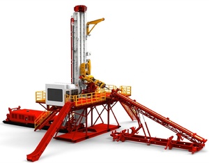
The foregoing objects are achieved by a workover rig which is mounted on a portable base platform such as a skid or the bed of a trailer vehicle, and which features a collapsible mast assembly which is movable from a reclining transport position to an erect elevated position of use. The mast assembly is supported for freestanding operation by a carriage assembly including a cantilever substructure support base mounted on the rig support platform for pivotable movement from the reclining transport position to an elevated position of use. The carriage assembly includes lift arms coupled in parallel relation intermediate the cantilever support structure and the rig support platform, thereby defining a parallelogram throughout the range of movement of the mast support assembly for maintaining the cantilever support base in parallel alignment with the base platform. According to this arrangement, the mast and the carriage assembly are separately collapsible for transport in a low profile, reclining position over the base platform to comply with the length and height limitations established for public highways. The mast and the carriage assembly are separately erectable to an elevated operating position overlying well head equipment which may be disposed at an elevation either above or below the elevation of the portable base platform. The mast is connected in hinged engagement with the carriage assembly, and both the carriage assembly and the mast are separately driven from the transport position to the erect operating position by linear hydraulic actuators. The linear hydraulic actuators in combination with the carriage assembly serve to stabilize the mast for free-standing operation and transmit mast load reaction forces through the portable base platform. An important feature of this arrangement is the cantilever support substructure which is extended to an elevated operating position beyond the portable base platform for carrying out workover operations adjacent elevated well head equipment. A further advantage of this arrangement is that the mast, mast support substructure, and draw works can be carried in a collapsed, low profile transport position and both erection and retraction of the mast and mast support assembly can be carried out without disturbing the cable reeving on the mast and draw works.
According to an important aspect of the invention, the workover rig is provided with a mast, a mast support substructure, and draw works in which the static load of the draw works is supported by a portable base platform member rather than being supported by the intermediate mast support substructure. In this arrangement, the draw works includes a linear hydraulic actuator having rod and housing elements in which one of the elements is anchored to the base platform with the other element being mounted for movement along the base platform through a stroke pathway which extends transversely with respect to the mast. The traveling sheaves are cooperatively reeved with hoist and snub cables for developing driving forces required for either hoisting or snubbing operations. The advantage of this arrangement is that the intermediate mast support substructure must support only the mast in an erect operating position with the substantial weight of the draw works being supported by the portable base platform. This arrangement permits the mast support substructure to be easily movable from the reclining, low profile transport position to the elevated workover position without the burden of the draw works. Hoisting and snubbing operations are carried out by the draw works which includes a linear hydraulic actuator carried on the base platform, a load engaging traveling block supported for vertical movement along the mast by hoist and snub cables, and by traveling sheaves carried by the actuator through a stroke pathway which is oriented transversely with respect to the mast. In this arrangement the load engaging traveling block is driven upwardly or downwardly along the mast in response to extension and retraction of the rod and housing elements of the hydraulic actuator.
In yet another important embodiment of the invention, a vertically adjustable stack assembly is provided for accomodating the existing elevation of well head flange connections. The vertically adjustable stack assembly includes an adjustable support column assembly anchoring the rig platform to the well head casing, and an adjustable support column assembly interposed between the well head casing and the mast for transferring the weight of the mast from the intermediate mast support structure to the well casing. The vertically adjustable stack assembly simultaneously anchors the portable base platform to the well head casing, thereby stabilizing the mast support substructure, while relieving the burden of the mast from the intermediate mast support substructure. This arrangement helps stabilize the mast for free-standing operation on the mast support substructure and for transmitting mast load reaction forces through the portable base platform, thereby eliminating the need of dead man anchor lines which would otherwise be required for stabilizing the mast and for reacting dynamic mast loads.
Finally, the portable workover rig of the invention is adapted to perform drilling operations by the combination of a vertically yieldable stab assembly which interconnects a powered drill sub with a traveling block for permitting vertical displacement of the powered drill sub during make-up and break-out operations while simultaneously reacting torque forces which arise in response to rotary forces applied to the drill string. The vertically yieldable stab assembly includes upstanding stab receptacles anchored to the top side of the traveling block and stab elements downwardly depending from the under side of the powered drill assembly for engagement with the stab receptacles. Each stab element is supported for vertical reciprocal movement between retracted and extended positions, and each stab element is yieldably biased to the fully extended position, thereby permitting vertical displacement of the power sub relative to the traveling block during the make-up and break-out operations while reacting torque forces which are produced by operation of the powered drill sub.
FIG. 3 is a top plan view of the workover rig of FIG. 1 with the mast and carriage assembly removed which illustrates the layout of the draw works and related equipment on the deck of a portable rig support platform;
FIG. 7 is a side elevational view of a skid mounted workover rig having draw works and an erectable mast constructed according to the teachings of the present invention;
FIG. 10 is a perspective view which illustrates the arrangement of sheaves and reeving of cables for conducting snubbing operations on the workover rig shown in FIG. 1;
FIG. 11 is a perspective view which illustrates the arrangement of sheaves and reeving of cables for conducting hoist operations on the workover rig shown in FIG. 1;
FIG. 16 is a front elevation view of the completed vertically adjustable stack assembly shown interconnecting the mast support substructure and the rig support platform with the flanged connector of a well head assembly;
FIG. 20 is an elevation view of the linear hydraulic actuator which illustrates the relative position of trunnions with sheaves removed, taken along the line XX--XX of FIG. 19;
Referring now to the drawings, and more particularly to FIGS. 1-4, a workover rig 10 is shown having a transportable mast assembly 12 and draw works 14 supported on a portable trailer platform 16. The trailer platform 16 includes the usual longitudinal side frame rails 18, 20 which supports forward and rear decks 22, 24, respectively. The side rails 18, 20 are interconnected by the usual structural members, including a tailboard 26. The trailer platform 16 includes a fifth wheel connection 28 for attachment to a tractor, and rear wheels 30 supported by shock assemblies and leaf springs in the usual manner. Outrigger jacks or props 32 support the side frame rails 18, 20 to prevent tilting or overturning of the rig during operation and also for maintaining the orientation of the trailer platform 16 once it has been set up. The jacks 32 are preferably hydraulically actuated and are controlled from a central station so that the trailer platform 16 can be aligned in parallel with the ground or inclined in a tilted position for workover of slant wells. Each jack 32 is equipped with a stabilizer pad 34 for engaging a mud sill (not shown) so that the trailer load can be more evenly distributed. Slung underneath the side frame rails 18, 20 are tool boxes 36 and a spare tire 38. Anchored top side on the forward deck 22 is power unit 40 which develops the main hydraulic power for the draw works 14 and includes hydraulic pumps driven by a diesel engine. The power unit is coupled to a hydraulic reservoir 42 so that as the required pressure in the system exceeds predetermined levels, one or another pump automatically unloads into the reservoir 42 and all engine horse power is then diverted for driving the alternate pump(s). Immediately forward of the power unit 40 are a pair of fuel tanks 44, and overlying the fifth wheel connection 28 is a hose basket 46. Overlying the fuel tanks is an upstanding stop bar 47 for engaging the mast assembly and supporting it in spaced relation with the forward deck overlying the power unit and fuel tanks when the transportable mast assembly 12 is disposed in its reclining transport position, as illustrated in FIGS. 1 and 2. Also anchored to the trailer platform 16 intermediate the forward and rear decks is a guide tube 48 which is straddled by the hydraulic reservoir 42 for receiving the movable actuator element of the draw works 14 as will be discussed in greater detail below.
Referring again to FIGS. 1-4, the transportable mast assembly 12 comprises generally an elongated mast 50 pivotally mounted on a mast support substructure 52 which is in turn pivotally mounted on a mast carriage assembly 54 which is mounted for pivotal movement from a transport position shown in FIG. 2 to an elevated position of use shown in FIG. 1. The mast 50 is formed by two upstanding mast sections 50A, 50B which are laterally spaced to define a vertical load transport zone 56 through which a traveling block 58 is transported during pipe running operations. The upper ends of the mast sections 50A, 50B are structurally interconnected by a crown block 60 which improves the mechanical stability of the mast and which also serves to support crown block sheaves in a manner to be disclosed hereinafter. Each mast section 50A, 50B is defined by four leg members 62A, 62B, 62C and 62D, and 64A-D, respectively. The leg members are generally arranged at the corners of a square with the forward leg portions terminating in a clevis which receives a hinge pin 66 which pivotally secures the forward legs to the mast support substructure 52. Each mast section 50A, 50B is provided with girt members 68 and brace members 70 which are structurally interconnected with the leg members to insure rigidity of each mast section. A clevis 72 is anchored on opposite sides of the mast support substructure 52 for anchoring the rear legs 62B, 64B of the mast when it has been erected to the upright position.
The mast carriage assembly 54 includes forward and a rear lift arms 76A, 76B, respectively, pivotally coupled in clevis connections intermediate the cantilever support base 74A and the rear deck 24 on laterally opposite sides of the draw works 14. The lift arms are all the same length and are spaced in parallel with each other whereby the combination of each pair of lift arms with the cantilever support base and the rear deck defines a parallelogram for maintaining the mast support substructure 52 in parallel alignment with the trailer platform 16 throughout the range of movement of the mast support substructure 52 from the reclining transport position to the elevated position of use. The mast support substructure 52 is extended and retracted between the reclining transport position and the elevated position of use by a pair of double acting, telescoping hydraulic actuators 78 having housing and rod elements pivotally coupled to clevis connections carried on the forward cantilever support base portion 74A and the rear deck 24 on laterally opposite sides of the draw works 14. The mast 50 is similarly erected by hydraulic lift cylinders 80 which are coupled for pivotal movement intermediate the forward cantilever support base portion 74A and the forward legs 62A, 64C of the mast sections 50A, 50B, respectively.
Erection of the mast 50 to the upstanding, elevated workover position is preferably carried out by rotating the mast support substructure 52 from its reclining transport position to its fully extended upright position while the mast 50 remains in its reclining position. After the mast support substructure has been fully stabilized in the upright position, the hydraulic lift cylinders 80 are actuated to cause the mast 50 to be pivoted to its upright standing position on the cantilever support base 74. The hydraulic lift cylinders 78, 80 are continuously pressurized in order to further stabilize the mast support substructure and transmit mast loads to the trailer platform 16. Retraction of the mast 50 is carried out in the reverse order by first uncoupling the rear leg portions at the clevis 72 and retracting the double acting hydraulic lift cylinders 80 until the mast 50 is substantially horizontal. Thereafter, the hydraulic lift cylinders 78 are retracted until the mast support substructure is resting in its reclining transport position with the upper end of the mast resting on the tie-down bar 47.
Referring now to FIGS. 1-4 and FIGS. 10 and 11, the principal components of the draw works 14 are the traveling block 58, a linear hydraulic actuator 92, a hoist power transmission system 94 and a snub power transmission system 96.
The traveling block 58 is guided for vertical displacement along the rear legs 62A, 64D, which serve as guides, as can best be seen in FIGS. 4 and 23. The traveling block 58 includes a main cross member 98 which extends horizontally between the legs 62D, 64D and is provided with guide rollers 100 rotatably mounted about shafts 102 at either end of the frame. The periphery of each roller is concave to conform to the shape of the tubular members 62D, 64D and vertically guide the traveling block as it is reciprocated along the mast 50. A rotary table 104 is carried by the main cross member 98 of the traveling block to facilitate workover or drilling operations.
The construction of the rotary table 104 is well known and includes a spindle 106 which is mounted for rotation in bearings 108 and is driven by a hydraulic motor 110 through a chain drive 112 coupled to its output shaft. The spindle 106 carries a flange 114 which supports a pipe gripping assembly 116 consisting of a slip bowl 118 and a snubber bowl 120 concentrically aligned to engage a length of pipe string extending through the central opening of the spindle 106. These fixtures are well known in the art and generally include a conical bowl having a set of pipe slips or jaws which are adapted to grip the periphery of the pipe string. The pipe gripping jaws can be moved into or out of engagement with the pipe surface by a hydraulic piston or by other power means. The slip bowl 118 is designed having its jaws 122 adapted to engage pipe string to prevent the weight of the pipe from causing the pipe to slip into the well hole. The snubber bowl 120 is equipped with jaws 124 which are adapted to engage the pipe to secure it against upward displacement, as for example, to restrain the pipe string against the well pressures, or for driving the pipe string when it is being pushed into a hole. The slip bowl and snubber bowl can be remotely operated by control means located for operator access at the operator platform 126 mounted on the mast 50 (FIG. 1). The power to raise and lower the traveling block 58 is provided by the linear hydraulic actuator 92 which is transmitted to the traveling block by the hoist and snub power transmission systems 94, 96, which will now be described.
Referring to FIGS. 3, 4, 10, 11 and 19-21, the linear hydraulic actuator 92 is carried on the rear deck 24 of the trailer platform 16 and includes rod and cylinder housing elements 128 and 130, respectively. The rod element 128 is rigidly attached at one end to an anchor weldment 132 whereby the actuator assembly 92 is supported in spaced, parallel relation with the rear deck 24 so that the cylinder housing 130 can move freely in extension and retraction. Reciprocal movement of the cylinder 130 is stabilized by the guide tube 48 which receives the freely projecting end of the cylinder housing 130. The anchor weldment 132 includes a socket for engaging a threaded shaft portion 134 of the rod element 128.
The linear hydraulic actuator 92 is double acting and includes a piston 136 slidably received within the cylinder housing 130 which partitions the interior of the cylinder housing into head and rod chambers 138 and 140, respectively. The rod element 128 comprises two concentric tubes 142, 144 for circulating hydraulic fluid into the head chamber 138 and rod chamber 140, respectively. The inner rod tube 142 has a bore 146 which connects the head chamber 138 in fluid communication with a stepped concentric blind bore 148 which communicates with a lateral hydraulic flow passage 150. Similarly, a lateral flow passage 152 communicates with an annular passage 154 which extends intermediate the inner rod tube and the outer rod tube. Hydraulic fluid discharged through the annular flow passage 154 circulates through discharge ports 156 which communicate with the rod chamber 140. Appropriate O-ring seals 158, 160 seal the pressure chambers against fluid leakage. An end cap 162 blocks off the end of the cylinder housing 130. It will be seen, therefore, that the piston rod element 128 remains fixed to the anchor weldment 132 so that pressurization of either the head or rod chamber of the cylinder housing 130 will cause the cylinder housing to extend or retract.
The reeving engagement of the hoist transmission system and the snub transmission system will not be described in connection with FIGS. 3, 10 11 and 21. The hoist power transmission system 94 applies a lifting force to the traveling block 58 which is developed by the linear hydraulic actuator 92, and also serves to transfer the load engaged by the traveling block 58 onto the mast 50. These functions are made possible by a pair of crown hoist sheave assemblies 184, 186 journalled in laterally spaced relation on the crown block 60 near the top of the mast 50. Base hoist sheaves 188, 190 are journalled near the bottom of the mast on a base sheave weldment 192 which is anchored to the tailboard 26, the aft deck 24 and the rod anchor weldment 132. Carried in reeved engagement with the crown hoist sheaves and the base hoist sheaves are hoist cable pairs 194, 196 which are firmly attached at one end to the top side of the traveling block 58 with the opposite end portions anchored to the base platform and tailboard. An intermediate length of each cable pair is extended upwardly along the mast, passing around the crown hoist sheaves 184, 186, respectively, extending downwardly along the mast and passing around the base hoist sheave assemblies 188, 190, respectively, extended forwardly along the aft dect 24 in parallel with the stroke pathway of the cylinder housing 130, passing around the traveling hoist sheave assemblies 174, 176, respectively, thence passing aft along the aft deck 24 and passing around the base hoist sheave assemblies 188, 190, respectively, and thence passing around the traveling hoist sheave assemblies once again thereby defining a multiple purchase of 4:1. In this arrangement, displacement of the cylinder housing will drive the traveling block a greater proportional distance through the load transport zone 56, thereby multiplying the stroke effect of the linear hydraulic actuator 92. For this arrangement, a nine foot stroke of the traveling sheaves is translated into a thirty-six foot traveling block stroke.
Extension and retraction of the cylinder housing 130 is controlled from the operator platform 126 which is horizontally supported from the aft legs of the mast at an elevation convenient for workover operations. The forward part of the platform (not shown) houses hydraulic valves that control the actuation of the various components as will be explained.
Referring now to FIG. 16, the workover rig 10 is set up adjacent a well site in which a well casing 230 is terminated by a lower well head flange 232 and is anchored by a concrete block 234 in the usual manner. As is conventional, a blow out preventer 236 is located above and connected to the lower well head flange 232. A slip 238 is located above and connected to the blow out preventer 236. Located above and connected to the slip is an energizable packer 240. The packer is coupled to an upper well head flange 242 disposed at an elevation above the trailer platform as indicated by the elevation reference line 244. The BOP slip and packer are all concentrically aligned with the well casing 230 so that a tubing string may be moved upwardly through the well casing along the bore axis 248 as the tubing string is run out of the well. Conversely, when running the tubing string 246 into the well, each section is moved downwardly through the packer, slip and blow out preventer into the well casing 230.
The blow out preventer 236 may be of any suitable type, but is preferably hydraulically energizable for engaging the tubing string 246 in a fluid sealing relation to prevent the well from blowing out. The slip 238 may also be of any suitable construction and is preferably double acting, i.e., is preferably capable of preventing both upward and downward movement of the production tubing string. The packer 240 may not be present on some well head installations, in which case the upper well head flange 242 is located at a different elevation. The precise elevation of the well head flange termination 242 varies from well to well depending upon the length of the well head equipment which is used for terminating the well. This variation in the elevation of the well head flange presents a problem for conventional portable workover rigs since the traveling block must be consentrically aligned with the well bore, and since it is generally desirable to interconnect the mast support substructure to the well casing to transfer the static weight of the mast from the mast support substructure to the well casing. As previously explained, it is also desirable to anchor the rig platform to the well casing to stabilize the free-standing mast and mast support substructure against wind loading and dynamic reaction forces developed during pipe running operations.
The lower support column assembly comprises a horizontal cross beam 254 which is adjustably connected to first and second upright support columns 256, 258 which are spaced in parallel with each other on laterally opposite sides of the flange connector 242. First and second struts 260, 262 project from the tailboard 26 of the trailer platform 16 for supporting the support columns 256, 258 in parallel alignment with the bore axis 248. The lower end of each support column 256, 258 is furnished with a threaded collar 264, 266, respectively, in which threaded posts 268, 270 are received in telescoping engagement. Because of this threaded, telescoping engagement, the effective length of the support columns is adjustable to drive a stack flange connector 272 carried by the cross beam 254 into compressive engagement with the well head flange connector 242. The stack flange connector 272 and the upper well head flange 242 each have through holes which are aligned for securely fastening the cross beam to the well head.
The upper support column assembly 252 is also vertically adjustable in order to transfer the weight of the mast from the cantilever support substructure 74 to the well casing 230. The upper support column assembly 252 comprises generally first and second upright support columns 286, 288 connected intermediate the cross beam 254 and the cantilever support substructure 74 on laterally opposite sides of the stack flange connector 272. The intermediate length of these upright support columns is vertically adjustable after the stack flange connector 272 has been secured to the well head flange connector 242 so that the weight of the mast 50 will be transferred from the cantilever support substructure 74 to the well casing 230. Sockets 290, 292 are anchored to the top side of the cross beam 254 on laterally opposite sides of the stripper bowl 280 for receiving the upright support columns 286, 288, respectively. The support columns are fastened in the sockets by means of through bolt and cap nut combinations 294. The upper ends of the upright support columns 286, 288 are threaded and project through the cantilever support substructure on opposite sides of the stationary slip bowl 75. The cantilever support base is connected to the upright support columns by means of lock nuts 296 tightened against the cantilever support base on both the top and bottom sides thereof. It is generally desirable to tighten the bottom lock nuts against the cantilever support base 74 to cause compression loading in the support columns 286, 288, so that the static load of the mast will be substantially transferred from the cantilever support substructure 74 to the well head casing 230. The upper lock nuts are also tightened so that upwardly directed snubbing loads will be transmitted through the adjustable stack connector assembly 228 to both the well head casing 230 and the trailer platform 16.
The bolster plates are provided with clevis fasteners 304, 306 for engaging the upright support columns 286, 288, respectively. Clevis bolts 308 secure the clevis fasteners to the upright support columns at a plurality of vertically spaced locations and intermediate the mast and the stack flange connector. Link elements 310, 312 are interconnected in a scissors arrangement on opposite sides of the bolster plates for permitting accordion-like movement of the bolster plates relative to each other in parallel stacked relation. When the intermediate length of pipe string 246 is received through the concentrically aligned openings 302, the vertically spaced bolster plates 300 cooperte to oppose radial deflection of the pipe string in response to severe compression loading. The link elements 310, 312 are pivotally suspended from the under side of the cantilever support base 74 and are anchored in place in spaced relation along the upper support columns by the clevis bolt fasteners. Any suitable number of bolster plates may be stacked, with the bolster spacing preferably being approximately one foot.
The drill power assembly 316 includes a drill sub 334 having a threaded pin connection 346 for engaging a box connection on the upper end of the pipe string 246. A hydraulic motor 348 is coupled to the drill sub for rotating it and the connected drill string in response to the flow of hydraulic fluid through a hydraulic connector 350. The drill sub 344 is journalled in a rotary bearing assembly 352. The threaded pin connection is enclosed by a stab guide housing 354 with the opposite end of the drill sub communicating with a fluid swivel connector 356. A BOP 358 rides on top of the swivel connector 356 and is coupled to a mud line 360 for circulating drilling fluid through the drill sub 316 and into the attached drill string as the drill sub is rotated.
When it is desired to work over an offshore well, the skid mounted transportable mast and draw works assembly 366 as shown in FIGS. 5 and 6, or alternatively, the skid mounted mast and draw works assembly 368 as illustrated in FIGS. 7, 8 and 9 is employed. In these arrangements, accessory equipment such as tools, power pack, pumps and other equipment are separately transported. Turning now to FIG. 5, the mast 50 is pivotally coupled to a mast support substructure 370 which is mounted on one end of a skid 372. The skid 372 is transported on a barge and when arriving at the offshore well, a heavy duty utility crane raises the skid mounted workover rig 366 on to the offshore platform adjacent the well head. The mast 50 is erected about a hinge pin 374 which is pivotally connected to the rear legs of the mast. A hydraulic lift cylinder 78 pivotally coupled between the skid and the mast drives the mast in rotation about the hinge pin 374 until the forward legs 62B of the mast are brought to a standing position on the mast support substructure 370 and locked into place by a suitable fastener. The hydraulic system is then connected to the power pack 40 which may be located at any convenient remote location.
Referring to FIG. 9, the skid 372 is formed by left and right side beams 376 attached to opposite sides of a structurally reinforced below-deck 378. The below-deck supports the linear hydraulic actuator 92 with the cylinder housing 130 being shown received within the guide tube 48. A super-deck 380 is anchored to the below-deck and is supported at an elevation above the linear hydraulic actuator and the associated sheave assemblies. Safety rails 382, 384 extend along the length of the super-deck on opposite sides thereof, and a pipe rack is secured to the super-deck intermediate the safety rails, thereby defining walkways 388, 390 intermediate the safety rails and the pipe rack. In the transport mode, the mast is carried in the pipe rack 386, and during workover operations pipe sections are stored in the pipe rack.

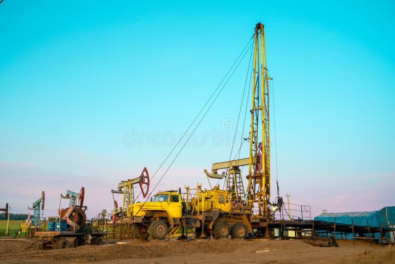
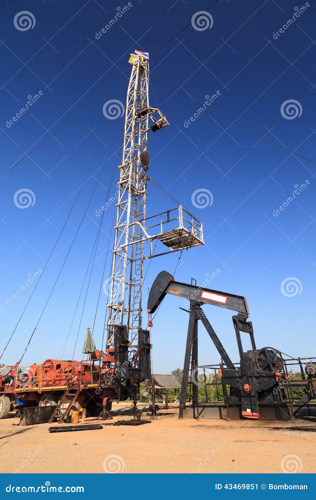
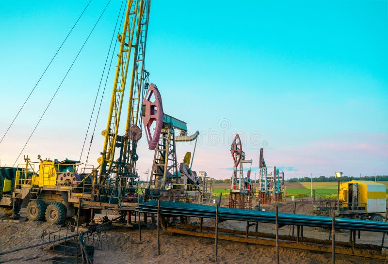
This paper describes the results obtained and the equipment and techniques used in setting up the first barge-assisted hydraulic workover operation in the Gulf of Thailand (GOT). This paper will discuss the hydraulic workover unit (HWU) selected to perform the operations along with the engineering modifications that were required to meet the operator"s requirements in the GOT, primarily installing electrical submersible pump (ESP) completions in depleting wells.
This website is using a security service to protect itself from online attacks. The action you just performed triggered the security solution. There are several actions that could trigger this block including submitting a certain word or phrase, a SQL command or malformed data.
The document applies to rotary drilling rigs, well servicing rigs, and special services as they relate to operations on location. First published in 1981, significant revisions in this edition of Recommended Practice 54 include a new section on flowback operations which is key for safe well testing, revised requirements for facility and site process hazard assessment and mitigation, and introduction of formal risk assessments as well as expanded provisions for offshore operations.


 8613371530291