
pulling unit vs workover rig manufacturer
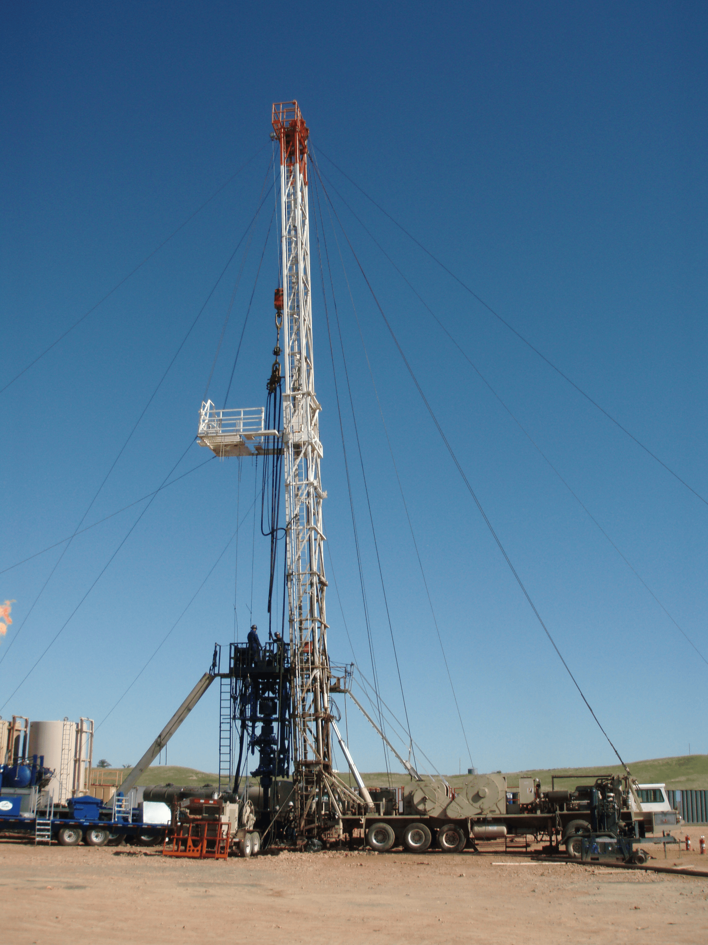
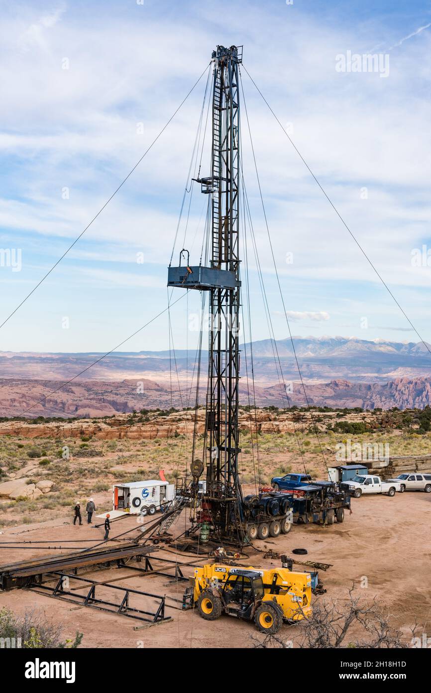
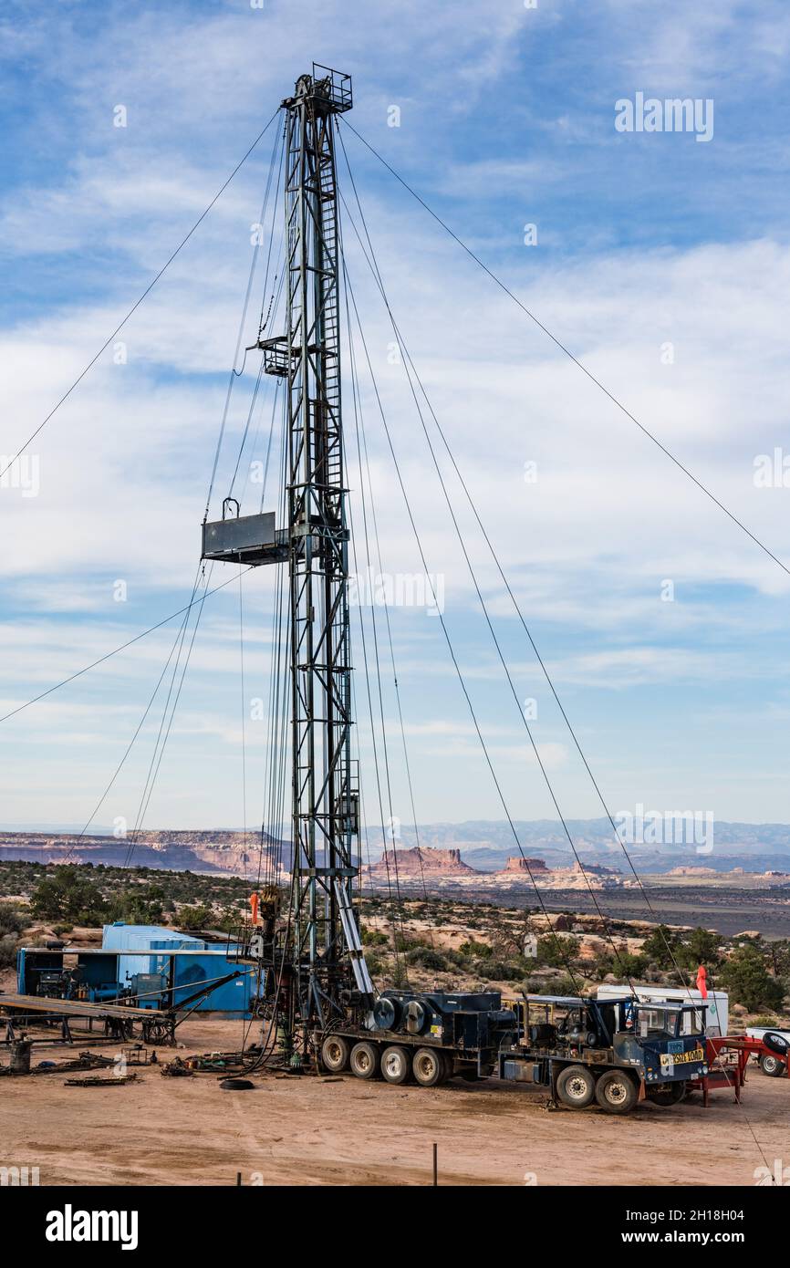
Workover rigs, also called pulling unit rigs, are specialized oil rigs set up for inserting or pulling pipe tubing in and out of wells. Workover crews are called when an oil well has been drilled, is undergoing repair or is being retired, as indicated by Schlumberger.
These crews are relatively small compared to other rig crews and consist of tool pushers, operators or relief operators, derrick men and floormen or roughnecks. The average workover rig salary overall was $65,039 as reported by Simply Hired in 2022. Available workover rig jobs and descriptions can be found on the Rigzone website.
The acting supervisor on a workover rig is called the tool pusher. The main task of a pusher is to hire, fire and supervise contracting work crews. When contractors have an issue on site, the first person they report concerns to is the tool pusher. Pushers need to have an intimate knowledge of how each and every part of a rig works, both individually and as an overall part of the drilling operation as a whole.
If equipment fails or needs to be reordered, the tool pusher talks with suppliers to get the right parts out on site with a minimum of downtime for the rig. The pusher is responsible for the overall safety of a rig. If the tool pusher has any safety concerns, he has the power to halt production until the concern is resolved.
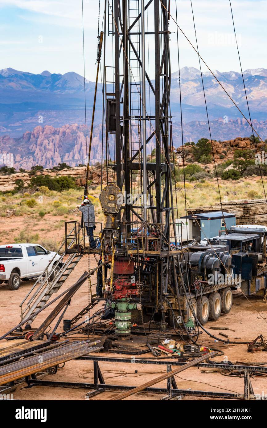
The operator/relief operator is next in order of responsibility to the tool pusher on a workover rig. The main task of an operator is to control the crane and derrick that hauls pipe in and out of the bored well. In smaller crews, the operator is also the one who drives the rig truck. When laying pipe into a well, the operator directs the truck or derrick to the optimum spot next to the bore opening.
The operator then instructs the derrick hands and roughnecks where to place the bore pipe for easy access by the crane or by hand-loading methods. During a well breakdown or repair, the operator directs the crew hands in storage of extracted pipelines. Because the operators work most closely with derrick hands and roughnecks, they are typically responsible for selection and maintenance of their immediate workover rig crew.
In the pulling unit rig crew hierarchy, the derrick hands come after the operator/relief operators. The main responsibility of a derrick hand is everything that is above ground on the rig. During laying operations, derrick hands assist the operators/relief operators in inserting boring into the well. During repair or breakdown, they assist the operator in pulling pipe out of the well and storing it properly.
In between laying, derrick hands have other responsibilities as well, depending on the size of the crews. In smaller crews, Derrick hands also see to the maintenance of the rig-based electric and diesel generators necessary to power rig equipment.
At the bottom of the pulling unit rig crew in terms of seniority is the floorhand or roughneck. The main task of a roughneck is to perform any kind of tasks asked by either the derrick hand or the operator. These tasks can range from assisting with laying new pipe or removal of old tubing, general construction, to moving new equipment, such as generators. Most crew members on a work-about start their career as a floorhand or roughneck before working their way up to more senior positions.
Snubbing units have evolved into one of the most capable and efficient well servicing tools in the oil & gas industry. In the 1920"s, the need for a rig to work with pressures at surface drove the invention of the snubbing unit. The first snubbing unit was primarily designed to work in well control situations to "snub" drill pipe and or casing into, or out of, a well bore when conventional well killing methods could not be used. The first snubbing unit relied on the draw works of the companion rig to supply its" power. A series of sheaves, cables and counter weights were rigged up so that as the rig"s traveling blocks hoisted up, the snubbing unit would snub in the hole. Conversely, when the traveling blocks on the rig were lowered, the snubbing unit would snub out of the hole. As you can imagine, this required close communication with several different contractors in order to perform the work safely and efficiently.
One of the main components of a snubbing unit is the slip. Stationary and travelling slips are operated in sequence to grip the pipe as it is snubbed into the well. Typically, a minimum of four slip bowls are used in snubbing operations. Two slip bowls are designated for "pipe light" operations. Pipe light is when the well bore forces are greater than the tubular weight in the well bore. The other two slip bowls are designated for "pipe heavy" operations. Pipe heavy occurs when either enough pipe has been snubbed into the well bore and fluid weight inside of the pipe is greater than the snub forces acting against the pipe in the well bore.
Modern snubbing units are powered by sophisticated hydraulic systems. These hydraulic units typically supply all power required by the components of a snubbing operation. With a better understanding of hydraulics and modern advances, companies have been able to harness this hydraulic energy to develop precision controlled snubbing units. These units move tubulars into and out of a well bore by use of a "multi cylinder jack"; a snubbing jack comes in many sizes depending on the task at hand. They are usually denoted in size by the snubbing unit description (i.e. 460K, 340K, 200K, etc). The 460K snubbing unit has the ability to lift 460,000 LBS and a snubbing capacity of 230,000 LBS. Most snubbing units can typically snub half of their lift rating. Assume you had a well with 10,000 PSI at surface and wished to snub in a string of 2 3/8" tubing. The snubbing contractor can calculate the snub force, add in their respective friction calculations and project the snub force to overcome will be approximately 51,000 LBS. This would put a 120K snubbing unit to close to its maximum capacity of 60,000 LBS snub loading. The safest bet would be a 150K or 235K snubbing unit.
Pipe handling is performed by the snubbing units "gin pole" and "pipe winches". The gin pole is typically telescoped out in excess of 40ft above the snubbing unit. With the use of dual tubing winches, multiple joints of pipe can be handled simultaneously, speeding up the operation.
The snubbing "basket" is the platform where the snubbing personnel work. The basket contains all of the necessary hydraulic controls to operate all the features of the snubbing unit, as well as a large bank of BOP"s and hydraulic valve controls.
Today"s snubbing units can be employed to provide a wide range of services. In essence, a snubbing unit is a hydraulic rig that can do everything a rig can do, plus it can perform under pressure in an under balanced live well state. This is especially critical to the operators in the Haynesville Shale, which is known for HPHT wells. With the use of the snubbing units" hydraulic rotary, the unit can be employed for fishing, milling, drilling, side tracking or any task needed to remove bridge plugs, cement or deepen wells.
The industry has become more aware of damages caused by heavy kill weight fluids and mud. This has helped make snubbing units more popular in a completion and workover role, versus its" traditional use as a well control response tool. With the advances in drilling technologies in the unconventional shale market, the benefits of snubbing units have become very apparent. These types of completions often have laterals extending out thousands of feet. With costly stimulations used to help extract the gas more efficiently, operators often times do not wish to turn around and load the well with heavy fluids to complete the well dead.
Coiled tubing has its limitations in reach, due to wall to wall mechanical friction in horizontal wells. Often times the coiled tubing units cannot reach TD or supply the needed weight on bit to mill up composite plugs typically used in completions.
Another clear advantage to using a snubbing unit is its" small footprint, which is critical on the tight locations in the unconventional shale"s. Moreover, the small size and ease of mobilizing is especially useful and cost effective with offshore wells.
In conclusion, with the snubbing unit"s size, ability to handle pressure, rotary capabilities, rigidity of jointed tubing and minimal wall contact, snubbing units have become the chosen resource for these types of completions.

Drilling calls for complex, carefully engineered equipment — and inevitably this equipment can wear down over time and require replacement. That’s where a workover rig comes in. Workovers are among the most expensive and complicated tasks in the drilling industry, so here are a few things you should understand about them.
A workover is a complex maintenance task that involves pulling completion hardware out of a well in order to extend the life of the well. A workover rig is a specially designed rig that makes it easier to take out or insert tubing into a well.
To complete a well servicing, the well is first killed. This halts the flow of fluids in the reservoir. The wellhead and flow line will then be removed and the completion hardware will begin to be pulled out of the well using the workover rig. Replacement parts will then be lowered into the hole accordingly.
Because workovers are involved in time-consuming processes, through-tubing workovers might be initiated, which can occur without forcing teams to kill a well and do a full well servicing. This might be considered first before deciding on a full well servicing.
A workover rig is needed when a well is no longer suitable for the drilling job it was originally built for. Maybe the production tubing has incurred damage over time or downhole tubing has stopped functioning correctly. Or perhaps the contents of the reservoir that the tubing is drawing from has changed and requires adjusted tubular components. In any case, the well is unable to perform efficiently and could even compromise the safety of those working on the well. At that point, its components must be replaced and a workover rig must be constructed.
This website is using a security service to protect itself from online attacks. The action you just performed triggered the security solution. There are several actions that could trigger this block including submitting a certain word or phrase, a SQL command or malformed data.

The rig assist unit was installed on top of the rig’s Bops. A landing joint was lowered into the stack and screwed into the tubing hanger. The snubbing Bops were tested using the rig pump to 35mpa
The stack was equalized using the snubbing unit equalize line to well bore pressure. The hanger hold-down screws were backed out and the tubing hanger staged out using the snubbing units annular and stripping rams
Every tubing connection was staged out of the hole using the stripping rams and annular. The pressure at 21mpa made pulling the connections through the annular with pressure under it unwise. Before the connection was pulled through the annular, the lower stripping rams were closed and the pressure between the rams and annular vented to flare. Once the connection was through the annular element, the chamber between the Bops was re-equalized and the stripping ram opened. This process was repeated for every connection
Once the lift force from the well overcame the weight of the string, the snubbing unit took over pipe movement. The tubing connections were still staged out and the pipe continued to be racked in the derrick
The joint was gently snubbed up until the fill/flow sub was above the snubbing unit annular element. The operator continued to raise the tubing until the lower connection of the 3m pup joint engaged the bottom side of the stripping rams. The rams were locked and the chamber between the stripping rams and annular was re-equalized
This website is using a security service to protect itself from online attacks. The action you just performed triggered the security solution. There are several actions that could trigger this block including submitting a certain word or phrase, a SQL command or malformed data.

We like to throw around “blog ideas” over here at Croft to help my fellow blog partner, Amy and I have a new fresh blog every week. We try to keep our readers up to date with both the new and the old. Someone threw out the idea of writing about a workover rig. Still being new to the industry, I snatched this topic up because I simply wanted to learn more about it myself! My main focus for this blog is simply discussing what is a workover rig and why it is important.
First off, maybe you know a workover rig by a different name. They can be called completion wells or pulling units. I just want to try to avoid any confusion! I am going to give Wikipedia’s definition first and then break it down to layman’s terms for those of you who don’t quite understand what the Wiki is trying to say (Like me). According to Wikipedia, “The term workover is used to refer to any kind of oil well intervention involving invasive techniques, such as wireline, coiled tubing or snubbing. More specifically though, it will refer to the expensive process of pulling and replacing a completion.” Let’s break down some of that Terminology…
Snubbing: This method is used in more demanding situations when wireline and coiled tubing does not offer the strength and durability needed. Snubbing runs the bottom hole assembly on a pipe string using a hydraulic workover rig.
So basically, the purpose of a workover rig is to replace a well with a fresh completion. This may have to happen due to the well deteriorating or the changing of reservoir conditions. This is performed if a well completion is unsuitable for the job at hand. An example of the well deteriorating is the equipment may have become damaged or corroded such as production tubing, safety valves, electrical pumps, etc. An example of the changing of reservoir conditions maybe if the flow of a well has decreased over time. If this happens, when the well was originally drilled, it was fit for tubing that was big enough for a higher flow of oil and gas. As the flow decreased, smaller tubing is now needed.
For a workover to take place, a well must be killed or in other words, stop the flow of oil or gas. This is an intense procedure for a workover to take place, so they are planned long in advance.

This website is using a security service to protect itself from online attacks. The action you just performed triggered the security solution. There are several actions that could trigger this block including submitting a certain word or phrase, a SQL command or malformed data.

We are committed to total customer satisfaction, achieving excellence in our operations through continuous improvement, development and empowerment of our people, and providing a positive contribution to our community.

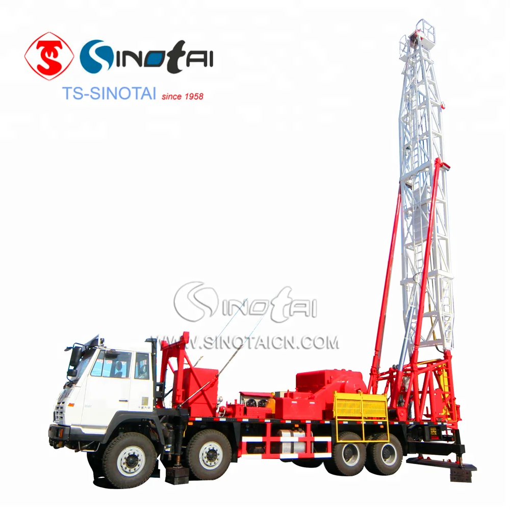
Workover rigs, also called completion rigs or pulling units, are specialized oil rigs set up for inserting or pulling pipe tubing in and out of wells. Workover crews are called when an oil well has been drilled, is undergoing repair or is being retired. Cotta manufactures a 3 shaft transfer case that is being used in workover rigs. The gearbox moves the power from the rear wheels, and while stationary over a well when the mast is up, it is used to run the draw works and winches.
Manufacturer of standard & mobile rigs & carriers for oilfield applications. Includes well servicing from 14,000 ft. to 22,000 ft., workovers from 10,000 ft. to 16,000 ft. & drilling from 6000 ft. to 10,000 ft. Specifications include brakes range from 28 in. dia. x 8 in. wide to 42 in. dia. x 12 in. wide, barrels from 12 3/4 in. x 38 in. to 18 in. x 43 in., chains from 1 1/4 in. to 1 3/4 in., clutches of 24 in. with single & 2 plate air friction outboards, shafts of 5 in. dia. to 6 1/2 in. dia. & gross weights from 63,200 lbs. to 115,000 lbs. Also includes forged steel, demountable options, mufflers with spark arrestors, dry type air cleaners, transmissions with torque converters, water splash brake cooling & up to 6 axles.
SCOPE: To provide a representative basis for determining the availability, capability, dependability, reliability of Stability Systems on Land Based Work-Over Rigs and the recommended practices and procedures for their safe use.
A typical double derrick with load guys in place in Figure 2-1. The sub-structure is in place and the unit properly configured to begin installation of the guying system. From this configuration determination can then be made as to the proper selection, location, configuration and holding capacity of guy anchors. Load guys should meet manufacturers recommendations. In the absence of manufacturers recommendations, the minimum wire rope diameter should not be less than that which is recommended by a representative of a major, oil field recognized, wire rope manufacturer.
The rig location area may grade away from the well bore along centerline II at a maximum drop of 1:20. The cross grades, parallel to centerline I, should be level. The area shall provide a minimum bearing capacity of 6000 psf.
Using the chart: An anchor in Zone "A" located a horizontal distance of 70 feet from the "Well Head" would require an anchor of what minimum holding capacity? On the chart move along the horizontal legend from left to right until you reach 70 feet. At this juncture proceed vertical until you intersect the curved line for Zone "A", now follow the intersecting horizontal line, left toward the vertical legend. We have now determined that the minimum holding capacity for the anchor, at this precise location, is 20,000 pounds.
Standing at the "Well Head", with the well bore immediately to your back, proceed North (in direction monkey board is facing) 24 paces. (The pace length is not as important as the numerical relationship of the units and the consistency of the unit length. The method will work with any unit of length as long as the same unit is used throughout.) Place a stake or other marker at this location (Bench Reference). Turn West 90 degrees and proceed forward 10 paces. At this location turn your body so that the front portion of your anatomy is approximately parallel to the radial of the guy anchor. If the northwest guy anchor is forward of your right shoulder and the southeast guy anchor is aft to the rear of your left shoulder, it can then be presumed that the radial angles are within acceptable parameters. Repeat the procedure from the bench reference, this time to the east, proceed ten paces. In this orientation the northeast anchor should be forward of the left shoulder and the southwest anchor should be aft of the right shoulder.
A survey of 13 drilling contractors operation 193 drilling rigs in northern Canada and Alaska indicated that there is a wide range of experience and operating practices under extremely low temperature conditions. While there is very little precise information available, there have been a sizeable number of failures in portable masts while in the lowering or raising process in winter. Thus the exposure to low temperature failures focuses on mast lowering and raising operations. Based on reports, however, this operation has been accomplished successfully in temperatures as low as -50 degrees F. While the risk may be considerably greater because of the change in physical characteristics of steel at low temperatures, operators may carry on "normal" operations even at extremely low temperatures. This may be accomplished by a program of closely controlled inspection procedures and careful handling and operation. This should reduce damage and impact loading during raising and lowering operations. At the present, there seems to be no widely accepted or soundly supported basis for establishing a critical temperature for limiting the use of these oilfield structures. Experience in the operation of trucks and other heavy equipment exposed to impact forces indicates that -40 degrees F may be the threshold of the temperature range at which the risk of structural failure may increase rapidly. Precautionary measures should be more rigidly practiced at this point. The following recommended practices are included for reference:
If maintained to these tolerances the sags will indicate a pretension of 1000 pounds for crown to ground guywires and 500 pounds for tubing board guywires. this is based on the use of 5/8 inch, 6x19, or 6x37 class, regular lay, ips, IWRC wire rope, installed according to the rigging guidelines set forth in chart depicted in Figure 5-5
All clips must be drop-forged steel; malleable iron clips must never be used. Wire Rope Clips, of the proper type, have the advantage of allowing thorough examination and ease of field installation. Properly installed wire rope clips will develop 80% of the rope strength. This 80% efficiency can only be assured if thimbles are used. A combined clamp and thimble unit is also capable of developing 80% of the wire rope strength.
The drawing on the following page, Figure 5-4, (SAME AS FIGURE 4-4) is another illustration of the continuing evolution of Rig Stability System engineering and design. It represents the latest API thinking relative to planing and preparing a Rig Stability System.
CAUTION: SOLE EMPHASIS SHOULD NOT BE PLACED ON PULL TESTING OR ALTERNATIVES TO PULL TESTING AS THIS MEASURES ONLY ONE COMPONENT OF THE RIG STABILITY SYSTEM.
The rig contractor should be responsible for the following: a. Insuring that anchor capacities are verified and that anchor spacing and capacity is suitable for the mast guying pattern and anticipated loading.
b. Records of pull testing or records of other methods used to verify temporary anchor capacity should be retained by the rig contractor until the job is complete and the guy wires have been removed from the anchors. The records should indicate the capacity of each anchor, the date of verification, name and phone number of the party responsible for verification, and the soil condition at the time of verification.
OUT OF AN ABUNDANCE OF CAUTION IT IS EXTREMELY IMPORTANT TO POINT OUT THAT THE PREVENTION OF RIG UPSET IS DIRECTLY DEPENDENT ON THE TOTAL INTEGRITY OF THE RIG STABILIZATION SYSTEM. THE SYSTEM INCLUDES ALL OF ITS COMPONENTS AND IS ONLY AS SOUND AS ITS WEAKEST MEMBER.
Our research has concluded, that the latest State-of-the-Art in RIG STABILIZATION is to be found in the pending American Petroleum Institute, Recommended Practice for MAINTENANCE and USE of DRILLING and WELL SERVICING STRUCTURES.

Well Service | Workover Rigs - 844/80 Double drum draw works. looks to be recently rebuilt. Has new Lebus Grooving on Tubing Drum. Comes w/ 250 HP 2 speed jackshaft/RA BOX. More Info
Well Service | Workover Rigs - CARDWELL KB200B Freestanding Oilfield Workover Rig / Service Rig / Pulling Unit, Service Rigs, Used Cardwell KB200B Freestanding Service Rig, 5 Axle Carrier, Detroit 8V71... More Info
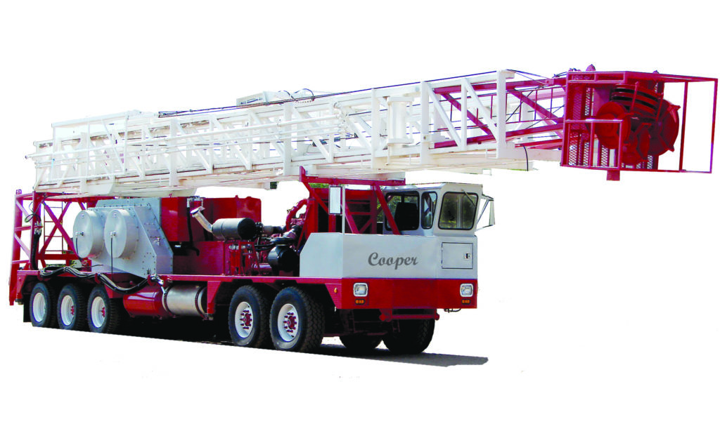
Well Service | Workover Rigs - WELL SERVICE RIG - COOPER 350 Well Service Unit p/b DETROIT 8V-92 Diesel Eng, ALLISON 750 Trans, 42X12-38x8 DRAWWORKS w/dual disc assist, 97â 200,000# Telescoping M... More Info
Well Service | Workover Rigs - CROWN 350 SERIES -- SERVICE KING 104" 205,000# DERRICK, CAT3406, ALLISON 5860,38X10 DOUBLE DRUM DRAWWORKS, CROWN SHEAVES REBUILT 2013 MAIN26âX4,SANDLINE 22â, NE... More Info
Well Service | Workover Rigs - 2008 Crown/Cabot 1058 Service unit mounted on 4 axle carrier w/Detroit 60 Power. New 5860 Drop Transmission. 72" Double rod/single tubing Derrickmast 125000# Rig is in Ex... More Info
Well Service | Workover Rigs - WELL SERVICE RIG - FRANKS 1287-160-DTD-HT D/D Well Service Unit p/b DETROIT 8V-71N Diesel Eng, ALLISON CBT-4460-1 Trans. SERVICE KING 96" 180,000# Hydraulically Raised & ... More Info
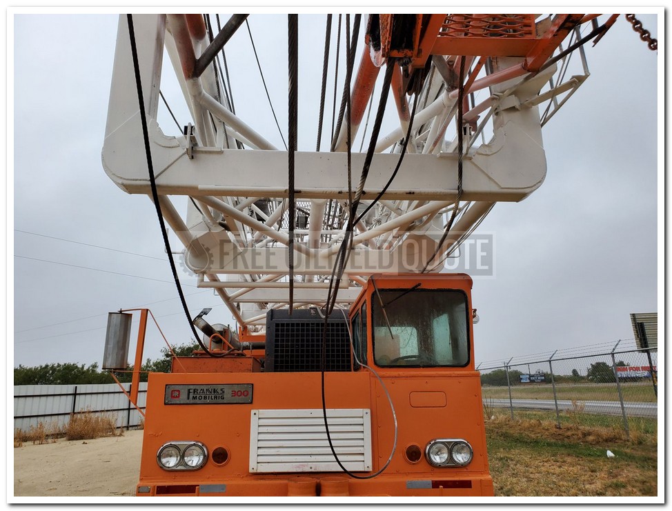
Well Service | Workover Rigs - FRANKS 300 D/D 1287 w/hydromatic brake, Well Service Unit p/b DETROIT 8V-71 Diesel Eng, ALLISON 750 Trans, (Reman Dec 2011) FRANKS 96âH 150,000# Tri-Scope Telescopin... More Info
Well Service | Workover Rigs - FRANKS 658 D/D Well Service Unit p/b CAT 3406 Diesel Eng, ALLISON HT-750 Trans, FRANKS 96âH 180,000# 4-Leg Telescoping Mast, Hydraulically Raised & Scoped w/4-Sheave... More Info
Well Service | Workover Rigs - FRANKS 658 D/D Well Service Unit p/b Series 60 Detroit Diesel Eng, ALLISON 5860 Trans, 102âH 225,000# (on 4 line) Telescoping Mast, Hydraulically Raised & Scoped, Db... More Info
Well Service | Workover Rigs - IDECO H35 96̢۪ 210,000 MAST, DETROIT 60 SERIES ENGINE, ALLISON 5860 TRANSMISSION, REFURB 2005, IDECO DERRICK REPLACED WITH NATIONAL DERRICK, TUBING DRUM CON... More Info
Well Service | Workover Rigs - IDECO RAMBLER H-35 Oilfield Workover Rig / Service Rig / Pulling Unit, Service Rigs, Used Ideco Rambler H-35 workover rig / service rig / pulling unit, 4 axle carrier, De... More Info
Well Service | Workover Rigs - 2015 INTERNATIONAL PAYSTAR 5900 Flushby Unit. C/w 2003, Refurbished in 2015, Western Fab Ltd. flushby unit, s/n 03-09-1008, 50 Ft. Mast height, 50,000 lb. pull rating, fr... More Info
Well Service | Workover Rigs - 2005 KENWORTH T800 Flusby Unit. C/w Lash Ent. flushby unit, 47 ft mast, slant compatible, 3x5 Gardner Denver triplex pump, 5000 psi, 2005 Advance 8m3 tank, TC 406 code, P... More Info
Well Service | Workover Rigs - 2003 KENWORTH T800 Flushby Unit. c/w Online flushby unit, 47 ft. mast, slant compatible, Pullmaster HL25 wotking winch, Pullmaster PL5 catline winch, 2002 wabash two comp... More Info
Well Service | Workover Rigs - 2005 KENWORTH T800B Flushby Unit. c/w Online flushby unit model 50-50, s/n 24641, 40 ft. mast,Salnt compatable, Pull master HL25 and PL5 winch, Gardner Denver 3x5 triplex... More Info
Well servicing rigs, also known as workover rigs or pulling units, are used in well completion, well maintenance and well abandonment operations. The well servicing and coiled tubing market rises and falls based primarily in conjunction with the number and type of new wells completed. Increased oil demand, rising oil prices and improved operator cash flow are expected to drive higher upstream investment going forward and lift the $5 billion well servicing and coiled tubing services markets in 2021 and beyond.
The coiled tubing services market includes the supply of coiled tubing services to drilling, completion, and production operations. The coiled tubing (CT) services market is now primarily driven by the use of CT units in place of well servicing units when completing horizontal wells. While production services, or well intervention, were the original application of coiled tubing, completion-related services now drive this market because continuous tubing can be tripped into a well more quickly than conventional tubing handled by a well servicing unit. However, with new horizontal laterals now regularly exceeding 10000’ in the US, coiled tubing runs into a mechanical limit. This is driving oil companies to large, high spec well servicing rigs for new well completions.
Snubbing is a process that controls the pressure of oil or gas in order to run or pull tubing, drill pipe, or casing. These applications use the standard snubbing unit to complete or re-complete wells in a “live well” condition. Any type of workover application can be performed utilizing quick jacks.
Snubbing units are often used in place of workover units for offshore applications. Snubbing can offer the same services at a greatly reduced cost to the customer. Snubbing can be performed on live and dean wells. Milling operations can be faster and more precise with snubbing units due to infinite control of torque and speed of the rotary mounted on the snubbing jack. Snubbing is versatile alternative that can overcome the limitations of other workover systems - wireline, coiled tubing and conventional workover rigs. It eliminates the use of kill fluids that can damage the producing formation and require costly disposal. Snubbing is also a faster solution. Snubbing units can often have the task completed before a conventional workover operation is even rigged up.


 8613371530291