
pulling unit vs workover rig free sample

The rig assist unit was installed on top of the rig’s Bops. A landing joint was lowered into the stack and screwed into the tubing hanger. The snubbing Bops were tested using the rig pump to 35mpa
The stack was equalized using the snubbing unit equalize line to well bore pressure. The hanger hold-down screws were backed out and the tubing hanger staged out using the snubbing units annular and stripping rams
Every tubing connection was staged out of the hole using the stripping rams and annular. The pressure at 21mpa made pulling the connections through the annular with pressure under it unwise. Before the connection was pulled through the annular, the lower stripping rams were closed and the pressure between the rams and annular vented to flare. Once the connection was through the annular element, the chamber between the Bops was re-equalized and the stripping ram opened. This process was repeated for every connection
Once the lift force from the well overcame the weight of the string, the snubbing unit took over pipe movement. The tubing connections were still staged out and the pipe continued to be racked in the derrick
The joint was gently snubbed up until the fill/flow sub was above the snubbing unit annular element. The operator continued to raise the tubing until the lower connection of the 3m pup joint engaged the bottom side of the stripping rams. The rams were locked and the chamber between the stripping rams and annular was re-equalized
This website is using a security service to protect itself from online attacks. The action you just performed triggered the security solution. There are several actions that could trigger this block including submitting a certain word or phrase, a SQL command or malformed data.

SCOPE: To provide a representative basis for determining the availability, capability, dependability, reliability of Stability Systems on Land Based Work-Over Rigs and the recommended practices and procedures for their safe use.
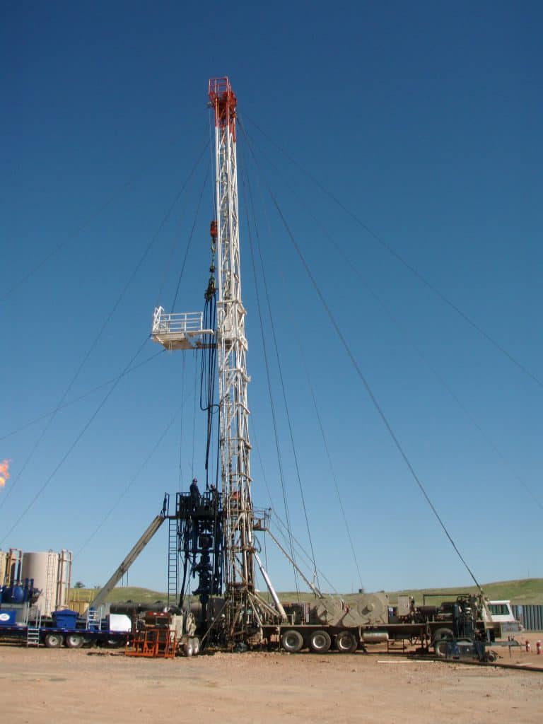
A typical double derrick with load guys in place in Figure 2-1. The sub-structure is in place and the unit properly configured to begin installation of the guying system. From this configuration determination can then be made as to the proper selection, location, configuration and holding capacity of guy anchors. Load guys should meet manufacturers recommendations. In the absence of manufacturers recommendations, the minimum wire rope diameter should not be less than that which is recommended by a representative of a major, oil field recognized, wire rope manufacturer.
The rig location area may grade away from the well bore along centerline II at a maximum drop of 1:20. The cross grades, parallel to centerline I, should be level. The area shall provide a minimum bearing capacity of 6000 psf.
Using the chart: An anchor in Zone "A" located a horizontal distance of 70 feet from the "Well Head" would require an anchor of what minimum holding capacity? On the chart move along the horizontal legend from left to right until you reach 70 feet. At this juncture proceed vertical until you intersect the curved line for Zone "A", now follow the intersecting horizontal line, left toward the vertical legend. We have now determined that the minimum holding capacity for the anchor, at this precise location, is 20,000 pounds.
Standing at the "Well Head", with the well bore immediately to your back, proceed North (in direction monkey board is facing) 24 paces. (The pace length is not as important as the numerical relationship of the units and the consistency of the unit length. The method will work with any unit of length as long as the same unit is used throughout.) Place a stake or other marker at this location (Bench Reference). Turn West 90 degrees and proceed forward 10 paces. At this location turn your body so that the front portion of your anatomy is approximately parallel to the radial of the guy anchor. If the northwest guy anchor is forward of your right shoulder and the southeast guy anchor is aft to the rear of your left shoulder, it can then be presumed that the radial angles are within acceptable parameters. Repeat the procedure from the bench reference, this time to the east, proceed ten paces. In this orientation the northeast anchor should be forward of the left shoulder and the southwest anchor should be aft of the right shoulder.
A survey of 13 drilling contractors operation 193 drilling rigs in northern Canada and Alaska indicated that there is a wide range of experience and operating practices under extremely low temperature conditions. While there is very little precise information available, there have been a sizeable number of failures in portable masts while in the lowering or raising process in winter. Thus the exposure to low temperature failures focuses on mast lowering and raising operations. Based on reports, however, this operation has been accomplished successfully in temperatures as low as -50 degrees F. While the risk may be considerably greater because of the change in physical characteristics of steel at low temperatures, operators may carry on "normal" operations even at extremely low temperatures. This may be accomplished by a program of closely controlled inspection procedures and careful handling and operation. This should reduce damage and impact loading during raising and lowering operations. At the present, there seems to be no widely accepted or soundly supported basis for establishing a critical temperature for limiting the use of these oilfield structures. Experience in the operation of trucks and other heavy equipment exposed to impact forces indicates that -40 degrees F may be the threshold of the temperature range at which the risk of structural failure may increase rapidly. Precautionary measures should be more rigidly practiced at this point. The following recommended practices are included for reference:
If maintained to these tolerances the sags will indicate a pretension of 1000 pounds for crown to ground guywires and 500 pounds for tubing board guywires. this is based on the use of 5/8 inch, 6x19, or 6x37 class, regular lay, ips, IWRC wire rope, installed according to the rigging guidelines set forth in chart depicted in Figure 5-5
All clips must be drop-forged steel; malleable iron clips must never be used. Wire Rope Clips, of the proper type, have the advantage of allowing thorough examination and ease of field installation. Properly installed wire rope clips will develop 80% of the rope strength. This 80% efficiency can only be assured if thimbles are used. A combined clamp and thimble unit is also capable of developing 80% of the wire rope strength.
The drawing on the following page, Figure 5-4, (SAME AS FIGURE 4-4) is another illustration of the continuing evolution of Rig Stability System engineering and design. It represents the latest API thinking relative to planing and preparing a Rig Stability System.
CAUTION: SOLE EMPHASIS SHOULD NOT BE PLACED ON PULL TESTING OR ALTERNATIVES TO PULL TESTING AS THIS MEASURES ONLY ONE COMPONENT OF THE RIG STABILITY SYSTEM.
The rig contractor should be responsible for the following: a. Insuring that anchor capacities are verified and that anchor spacing and capacity is suitable for the mast guying pattern and anticipated loading.
b. Records of pull testing or records of other methods used to verify temporary anchor capacity should be retained by the rig contractor until the job is complete and the guy wires have been removed from the anchors. The records should indicate the capacity of each anchor, the date of verification, name and phone number of the party responsible for verification, and the soil condition at the time of verification.
OUT OF AN ABUNDANCE OF CAUTION IT IS EXTREMELY IMPORTANT TO POINT OUT THAT THE PREVENTION OF RIG UPSET IS DIRECTLY DEPENDENT ON THE TOTAL INTEGRITY OF THE RIG STABILIZATION SYSTEM. THE SYSTEM INCLUDES ALL OF ITS COMPONENTS AND IS ONLY AS SOUND AS ITS WEAKEST MEMBER.
Our research has concluded, that the latest State-of-the-Art in RIG STABILIZATION is to be found in the pending American Petroleum Institute, Recommended Practice for MAINTENANCE and USE of DRILLING and WELL SERVICING STRUCTURES.
The term workover is used to refer to any kind of oil well intervention involving invasive techniques, such as wireline, coiled tubing or snubbing. More specifically, a workover refers to the expensive process of pulling and replacing completion or production hardware in order to extend the life of the well.
Workovers rank among the most complex, difficult and expensive types of wellwork. They are only performed if the completion of a well is terminally unsuitable for the job at hand. The production tubing may have become damaged due to operational factors like corrosion to the point where well integrity is threatened. Downhole components such as tubing, retrievable downhole safety valves, or electrical submersible pumps may have malfunctioned, needing replacement.
In other circumstances, the reason for a workover may not be that the completion itself is in a bad condition, but that changing reservoir conditions make the former completion unsuitable. For example, a high productivity well may have been completed with 5½" tubing to allow high flow rates (a narrower tubing would have unnecessarily choked the flow). Some years on, declining productivity means the reservoir can no longer support stable flow through this wide bore. This may lead to a workover to replace the 5½" tubing with 4½" tubing. The narrower bore makes for a more stable flow.
Before any workover, the well must first be killed. Since workovers are long planned in advance, there would be much time to plan the well kill and so the reverse circulation would be common. The intense nature of this operation often requires no less than the capabilities of a drilling rig.
The workover begins by killing the well then removing the wellhead and possibly the flow line, then installing a B.O.P commonly known as a blowout preventer, then lifting the tubing hanger from the casing head, thus beginning to pull the completion out of the well. The string will almost always be fixed in place by at least one production packer. If the packer is retrievable it can be released easily enough and pulled out with the completion string. If it is permanent, then it is common to cut the tubing just above it and pull out the upper portion of the string. If necessary, the packer and the tubing left in hole can be milled out, though more commonly, the new completion will make use of it by setting a new packer just above it and running new tubing down to the top of the old.

Drilling Operations. Drilling operations will be carried out using electrical rig for well. Drilling unit for drilling of oil and gas wells consists of a derrick at the top of which is mounted a crown block and a hoisting block with a hook. From the swivel is suspended a Kelly stem which passes through a square or hexagonal Kelly bush which fits into the rotary table. The rotary table receives the power to drive it from an electric motor. The electric motor rotates the rotary table, through which passes the Kelly bush, and the rotations are transmitted to the bit as the drilling progresses, the drill pipes in singles are added to continue the drilling process. At the end of the bit life, the drill pipes are pulled out in stands and stacked on the derrick platform. A stand normally has 3 single drill pipes. After changing the bit, the drill string is run back into the hole and further drilling is continued. This process continues till the target depth is reached. During the course of drilling, cuttings are generated due to crushing action of the bit. These cuttings are removed by flushing the well with duplex/triplex mud pumps. The mud from the pump discharge through the rotary hose connected to stationary part of the swivel, the drill string and bit nozzles. The mud coming out of the bit nozzles pushes the cuttings up hole and transports them to the surface through the annular space between the drill string and the hole. The mud not only carries away crushed rock from the bottom of the hole but it also cools the bit as it gets heated due to friction with formation while rotating. The mud also helps in balancing subsurface formation pressures and by forming a cake on the walls of the well also diminishes the possibility of crumbling or caving of the well bore. At the surface, the mud coming out from well along with the cuttings falls in a trough, passes through the solids control equipment"s i.e. shale shaker, de-sander/ de-silter and mud cleaner. These equipment"s remove the solids of different sizes, which get mixed with the mud during the course of drilling. The cleaned mudflows back to the suction tanks to be again pumped into the well. The drilling mud/fluid circulation is thus continuous cyclic operation. The most suitable clay for mud preparation is bentonite, which is capable of forming highly dispersed colloidal solutions. Various other chemicals are also used in mud preparation as per requirements dictated by the temperature/pressure conditions of the wells. The mud i...SaveCopy

Rig means the vessel described in Recital (A) hereto and includes any share or interest therein and her engines, machinery, boats, tackle, outfit, spare gear, fuel, consumable or other stores, belongings and appurtenances whether on board or ashore and whether now owned or hereafter acquired (but excluding therefrom any leased equipment owned by third parties);

Audrey Leon chats with Schlumberger, Baker Hughes and Weatherford to learn about the latest technologies available for rigless plugging and abandonment operations.
Euan Stephen, rigless intervension system (RIS) manager, Baker Hughes:[Baker Hughes] currently has two different units within our rigless abandonment fleet, the Mastiff Rigless Intervention System (RIS) and the Retriever Jacking Unit System (JUS). The RIS is a portable, modular, mast-style unit with a 320-tonne pulling capability delivered via a winch and travelling block. This unit can be configured in several different ways, depending on the operator’s requirements. This includes provisions for well control and drillpipe racking to reduce in-hole tripping time. Once installed at the wellsite, the RIS has full X-Y axis skidding capability. This capability requires the unit to be rigged up only once to gain access to all well slots in a short time. The JUS is also a modular design. The unit’s pulling capability is delivered by hydraulic cylinders and has a maximum pull of 200-tonne. Integrated into the unit are power tongs, a guillotine saw and a dual-drill machine, all essential equipment in the tubular recovery process. The unit also has full X-Y axis skidding ability to deliver the same time-saving, single-rig-up benefits as the RIS.
Rod Smith, integrated well abandonment global operations manager, Schlumberger:In the current landscape of abandonment, higher well complexity, increasing regulation, and well integrity issues have all combined to increase the challenge of achieving full isolation using a rigless methodology.
Currently, Schlumberger is working on several new technologies focused specifically on rigless abandonment. Specific to subsea wells, the Subsea Services Alliance (a collaboration among Helix, Schlumberger, and OneSubsea, a Schlumberger company) is developing the first riserless open-water abandonment module (ROAM) system (OE: April 2017). Enhancing the capabilities of the well intervention vessel by providing 18¾-in full-bore access, ROAM is deployed after the reservoir isolation phase and allows tubing to be pulled in open water safely and with environmental containment. Once the tubing is removed, the well intervention vessel can perform the upper abandonment. The system offers a flexible and cost-effective alternative to rig-based P&A well isolation more safely and with environmental containment.
Delaney Olstad, global business development manager – well abandonment & intervention services, Weatherford: The Rig-Free pulling and jacking unit (PJU) is an integrated system for efficiently completing offshore well abandonment and intervention operations. These systems are designed to complete tasks normally performed by a jackup rig or workover unit, but at a lower cost and with a higher degree of safety. It is well-suited for pulling tubulars and conductors on platforms with downgraded structural capacities and in situations where space is limited.
To accommodate a wide range of operations while being adaptive to platform limitations, Weatherford has two versions of the PJU. Each PJU has a hydraulically powered telescoping mast, which sits directly above the well center and incorporates a power swivel for rotating pipe and equipment. There is also a compact yet powerful jacking system integrated into the work floor. On the heavy-duty pulling and jacking unit, these elements offer a pulling capacity of 220,000 lbs (99,790 kg) in 60ft (18.2m) increments and a jacking capacity of 600,000 lbs (272,155 kg) in 5ft (1.5m) increments. The light-duty PJU provides a pulling capacity of 35,000 lbs (15,8676 kg) with a stroke of 44ft (13.4m) and can jack in 5ft (1.5m) increments at up to a capacity of 1 million lbs (453,592 kg).
ROAM is engineered and being built at the OneSubsea manufacturing facilities. The system is leveraging existing in-house technologies such as BOPs from Cameron, a Schlumberger company, and workover controls technologies from OneSubsea, packaged into a fit-for-purpose solution. Available later in the year, ROAM will complement existing intervention riser systems (IRS) and subsea intervention lubricators (SIL), expanding applications by enabling completions recovery in open water with environmental control and full well isolation capability without the need for a riser to surface—saving considerable running time.
Delaney Olstad, Weatherford:Our pulling and jacking units have been in operation for a decade, primarily in the Gulf of Mexico. They have also been deployed in the Asia Pacific market. The modular design of the system allows for rapid mobilization and efficient assemblage on the platform. Once on location, an innovative self-clamping skidding assembly enables movement from well to well without the need to rig down any main system components. The numerous capabilities of the PJU also allow it to conduct the majority of operations without assistance from the platform crane, facilitating simultaneous operations. By reducing the time spent on setup and well-to-well relocation, in addition to the minimal need for crane support, the PJU saves time and money.
Euan Stephen, Baker Hughes:Using a specially designed Retriever JUS for a tubing, casing and conductor removal operation in the southern North Sea from February to April 2017 eliminated the requirement for mobilizing a jackup. This resulted in cost savings of approximately £20 million (US$25 million) to the operator since mobilizing a rig would have required removing a considerable amount of subsea pipe work.
Euan Stephen, Baker Hughes: The main benefit of using rigless intervention systems is that mobilization of a jackup rig or full-size platform rig can be avoided, providing significant cost savings to the operator. The biggest benefit of the Baker Hughes rigless abandonment offerings is flexibility. Having two units with different designs means the ability to install units on a variety of platform sizes while providing a cost-effective solution. The unit can be supplied in a basic, lighter-weight version and can also be supplied with additional enhancements to deliver options such as drillpipe racking, well control, surface rotation and integration of services from other product lines.
Rigless intervention systems are used for platform applications. It is important that the platform can accommodate the size of the respective unit and handle the combined load of RIS unit weight + maximum pulling capacity, as this will be transferred to the platform substructure. It is not water depth, but the size of the platform, load capability and occasionally bed space, that determine whether RIS is a good option.
Rod Smith, SLB:As the industry looks to address the abandonment process in its entirety, there will probably be an application for using these Schlumberger technologies in most scenarios. The key benefit of simplifying equipment spreads with more intervention-enabled deployment methods is in reducing reliance on costly and complex drilling rigs while reducing the support costs for operations. High-cost applications such as subsea wells and complex abandonment environments will realize the greatest cost, risk, and efficiency benefits.
Delaney Olstad, Weatherford:As efficiency and profitability become increasingly important throughout the industry, the need for cost-effective, compliant abandonment and intervention resources is critical. Our innovative Rig-Free PJU has demonstrated its ability to improve efficiencies and limit the expense of abandonment and intervention operations.
The primary innovation and benefit of the Rig-Free pulling and jacking unit is in the name—it eliminates the need to employ costly jackup and workover rigs for offshore abandonment and intervention campaigns. For well abandonment or intervention operations involving multiple wells, the elimination of a rig can represent tens of millions of dollars in savings.
With the ability to improve the efficiency for both plug-and-abandonment and late-stage intervention, the Rig-Free PJU has already changed the well economics for many of our customers by increasing operational efficiencies and reducing overall operating costs.

This website is using a security service to protect itself from online attacks. The action you just performed triggered the security solution. There are several actions that could trigger this block including submitting a certain word or phrase, a SQL command or malformed data.

Cleans and services drilling subs and equipment before removing them from rig floor. The Floorhand’s job is to safely and efficiently operate the equipment on…
Including pulling cable, setting up mobile substations, switching trailers and cable spooling units. Willingness to install and demobilize temporary equipment…
Spot in, rig up, and rig down well service unit (rig). Minimum of 1 year operating rig. Workover rig experience (minimum 6 months verified experience).
Coordinate all equipment and crew during rig-up/rig-down of each well. Must be able to rig-up, operate, and troubleshoot multi-well ESD systems, and assist with…
A Floorhand is a crew member whose primary work station is on the rig floor. Assist with repairs and maintenance of large mud pumps, shale shaker, desander and…
Coordinate all equipment and crew during rig-up/rig-down of each well. Must be able to rig-up, operate, and troubleshoot multi-well ESD systems, and assist with…
If you have a pickup truck that’s 3/4 ton or greater that can handle one unit at a time OR up to three-unit combinations with our haul-and-tow vehicles, you can…
Assist Field Service Technician and rig hands in the pulling and installation of submersible equipment. A Spooler will be responsible for pulling, installing…
Coordinate all equipment and crew during rig-up/rig-down of each well. Must be able to rig-up, operate, and troubleshoot multi-well ESD systems, and assist with…
Reports any safety hazards, accidents or maintenance issues to the rig supervisor. Responsible for all elevated work associated with rigging up/down (i.e.…
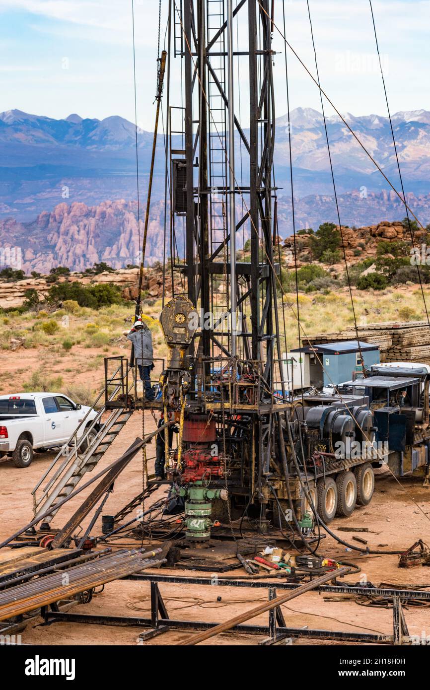
Workover rigs, also called well servicing rigs, completion rigs or pulling units, are specialized mobile units set up for inserting or pulling tubulars, sucker…
Knowledge of how pumping units run. Prepare and set up rig for work-over. Loads and off-loads pipe and assists in rig movement. Knowledge of types of pipe.

We like to throw around “blog ideas” over here at Croft to help my fellow blog partner, Amy and I have a new fresh blog every week. We try to keep our readers up to date with both the new and the old. Someone threw out the idea of writing about a workover rig. Still being new to the industry, I snatched this topic up because I simply wanted to learn more about it myself! My main focus for this blog is simply discussing what is a workover rig and why it is important.
First off, maybe you know a workover rig by a different name. They can be called completion wells or pulling units. I just want to try to avoid any confusion! I am going to give Wikipedia’s definition first and then break it down to layman’s terms for those of you who don’t quite understand what the Wiki is trying to say (Like me). According to Wikipedia, “The term workover is used to refer to any kind of oil well intervention involving invasive techniques, such as wireline, coiled tubing or snubbing. More specifically though, it will refer to the expensive process of pulling and replacing a completion.” Let’s break down some of that Terminology…
Snubbing: This method is used in more demanding situations when wireline and coiled tubing does not offer the strength and durability needed. Snubbing runs the bottom hole assembly on a pipe string using a hydraulic workover rig.
So basically, the purpose of a workover rig is to replace a well with a fresh completion. This may have to happen due to the well deteriorating or the changing of reservoir conditions. This is performed if a well completion is unsuitable for the job at hand. An example of the well deteriorating is the equipment may have become damaged or corroded such as production tubing, safety valves, electrical pumps, etc. An example of the changing of reservoir conditions maybe if the flow of a well has decreased over time. If this happens, when the well was originally drilled, it was fit for tubing that was big enough for a higher flow of oil and gas. As the flow decreased, smaller tubing is now needed.
For a workover to take place, a well must be killed or in other words, stop the flow of oil or gas. This is an intense procedure for a workover to take place, so they are planned long in advance.

E21B7/023—Drilling rigs characterized by means for land transport with their own drive, e.g. skid mounting or wheel mounting the mast being foldable or telescopically retractable
Improvements to base beams and self-propelled derrick rigs are described. The base beam can have two or more stabilizer arms which can be deployed. The base beam is also designed to support the derrick rig. An optional counterweight assembly can be connected to the front of the rig. The self-propelled derrick rig can be easily and quickly mounted to the base beam, and when mounted, the assembly will be able to withstand high hook loads and wind loading without the danger of the rig coming off of its wheels or falling over.
This disclosure relates to apparatus and methods of stably supporting self-propelled derrick rigs such as workover rigs, drilling rigs, cranes and the like, using a portable base beam. BACKGROUND
A completion or workover rig is used to do repair work on a well, such as tubing or pump replacement. When a workover rig is used to do repair work on a well, the rig must be able to pull weights near the rated capacity of the derrick of the rig, withstand high wind gusts, and otherwise be stably supported. Further, a workover rig should operate to its design capacity on a high frequency basis, and be highly mobile and self-contained.
A trend in workover rigs to maintain mobility and higher load capacities has been to use guy wires to stabilize the rig. The use of guys can significantly increase the rated capacity of the rig without changing the basic design.
However, there are drawbacks to a guy system. For example, guy wires need to be in specific locations for the stability and safe operation of the rig, and setup time is longer with a guy setup due to the specific locations. In addition, workover rigs typically tie off to permanent anchors set in the ground in a rectangular pattern around the well head. However, with the growing utilization of multi-well pads, it is nearly impossible to guy the workover rig to the anchors that were originally set in the ground when the well was drilled.
Solutions have been sought to solve the problem of a workover rig not being able to be supported by permanent anchors. One solution has been to utilize one or more base beams that are heavy, portable structures placed on the ground and to which the workover rig is guyed. Existing base beams have a relatively small footprint as well as set locations with which to attach guy wires, which makes set-up easier and faster. SUMMARY
Improvements to base beams and self-propelled derrick rigs are described. A self-propelled derrick rig as used herein is intended to encompass any type of self-propelled vehicle that has a derrick structure mounted on it which can be moved to a raised position during use, a driver"s cab and an engine for propelling the vehicle. Examples of self-propelled derrick rigs include, but are not limited to, workover rigs, drilling rigs, cranes and the like.
When the self-propelled derrick rig is mounted to the base beam, the assembly will be able to withstand high hook loads and wind loading without the danger of the rig coming off of its wheels or falling over. The self-propelled derrick rig can be easily and quickly mounted to the base beam. The assembly also allows support equipment, for example a portable pipe handling machine in the case of a workover rig, to work alongside it. In addition, the base beam can be transported as a single load on a vehicle, for example on a flatbed truck.
The base beam includes stabilizer arms that are attached, for example pivotally attached, to the base beam to help stabilize the base beam and the rig itself. A height adjustable stabilizer pad can be connected to each stabilizer arm to help level the stabilizer arms and the base beam on the ground.
In addition, to the base beam, a unique counterweight assembly is described that in use is connected to the front of the rig to help stabilize the rig and prevent the front of the rig from coming off of the ground.
In one embodiment, a base beam that is used to support a self-propelled derrick rig includes a longitudinally extending metal main beam having first and second opposite ends, a front side, a back side, a top and a bottom, where the bottom is substantially planar. The main beam includes a central section approximately midway between the first and second ends thereof on which the derrick structure of the rig will be supported. The central section can reinforced between the top and the bottom, and the top of the central section is substantially planar. First and second stabilizer arms are attached, for example pivotally attached or non-pivotally attached, to the main beam. when pivotally attached, the stabilizer arms are pivotable relative to the main beam between a refracted or transport position where the first and second stabilizer arms are generally parallel to the main beam and a fully extended or deployed position where the first and second stabilizer arms are not parallel to the main beam. In addition, at least one guy attachment point is provided on each of the first and second stabilizer arms to allow guys to attach between the derrick structure and the stabilizer arms.
In still another embodiment, an assembly is provided that includes a base beam and a self-propelled derrick rig. The base beam can include a longitudinally extending metal main beam having first and second opposite ends, a front side, a back side, a top and a bottom, and a central section. First and second stabilizer arms can be attached, for example pivotally attached or non-pivotally attached, to the main beam. When pivotally attached, the stabilizer arms are pivotable relative to the main beam between a retracted position where the first and second stabilizer arms are generally parallel to the main beam and a fully extended position where the first and second stabilizer arms are not parallel to the main beam. The self-propelled derrick rig can include a derrick structure adjacent a first end of the rig that is disposed in a raised position, a driver"s cab, and an engine that provides power for propelling the rig. A base of the derrick structure can be supported on the central section of the main beam on the top thereof. In addition, a plurality of guys extend between the derrick structure and the rig, and a plurality of guys extend between the derrick structure and the base beam.
In yet another embodiment, the counterweight assembly includes a sled that has a mechanism to connect the sled to the self-propelled derrick rig. The connection can be the sled simply resting on the front of the rig to weigh down the front end, or the sled can be removably attached to the rig. A plurality of weights are removably disposed on the sled. Each weight is individually separable from the other weights and each weight is individually removable from the sled.
In another embodiment, a method of supporting a derrick structure of a self-propelled derrick rig is provided, where the derrick structure is disposed adjacent to a first end of the rig and is movable between a raised position and a lowered position. In the method, a base beam is arranged on the ground, and stabilizer arms that are pivotally or non-pivotally connected to the base beam are deployed from a retracted position to a fully deployed position. The self-propelled derrick rig is arranged adjacent to the base beam, and the derrick structure of the self-propelled derrick rig is raised to the raised position. A base end of the derrick structure is attached to the base beam. In addition, a plurality of guys are attached between the derrick structure and the remainder of the rig and a plurality of guys are attached between the derrick structure and the base beam.
In another embodiment of a method, a base beam is arranged on the ground, and the self-propelled derrick rig is arranged adjacent to the base beam. The derrick structure of the self-propelled derrick rig is raised to the raised position, and a base end of the derrick structure is attached to the base beam. A plurality of guys are attached between the derrick structure and the remainder of the rig and a plurality of guys are attached between the derrick structure and the base beam. A counterweight assembly is also connected to the rig at a second end thereof opposite the first end and the derrick structure to weigh down the front of the rig. DRAWINGS
As described in further detail below, an improved base beam is described that is used to support a self-propelled derrick rig. A self-propelled derrick rig as used herein is intended to encompass any type of self-propelled vehicle that has a derrick structure mounted on it which can be moved to a raised position during use, a driver"s cab and an engine for propelling the vehicle. Examples of self-propelled derrick rigs include, but are not limited to, workover rigs, drilling rigs, cranes and the like. The self-propelled derrick rig will be described below as, and is illustrated in the drawings as, a workover rig. However, the derrick rig can be any other type of rig that can benefit from being supported using a base beam(s) as described herein.
With reference initially to FIG. 1, an assembly 10 is illustrated that includes a base beam 12 that is shown together with a self-propelled derrick rig 14 in the form of a workover rig. The base beam 12 is disposed adjacent to a well head 16, with the rig 14 being used to perform a service function on the well.
The rig 14 includes a derrick structure 18 disposed adjacent to a first or rear end of the rig, where the derrick structure includes a raised position (shown in FIG. 1) and a lowered position (shown in FIG. 4). The rig 14 also includes a platform 20, a driver"s cab 22 disposed on the platform adjacent to a second or front end of the rig, wheels 24 mounted on the platform 20, and an engine 26 adjacent to the front of the rig that provides power for propelling the rig during driving of the rig.
In the raised position of the derrick structure 18 shown in FIG. 1, a base of the derrick structure 18 is supported on the base beam 12. In addition, a plurality of guys 28 extend between the derrick structure 18 and different points on the remainder of the rig 14, and a plurality of guys 30 extend between the derrick structure 18 and the base beam 12.
In the illustrated embodiment, when fully deployed, the swing arms 52 a, 52 bextend from the front side 44 of the main beam and are disposed at generally right angles to the longitudinal axis A-A. As shown in FIG. 2, each of the first and second swing arms has a length L, and the combined length of the first and second swing arms 52 a, 52 bcan be less than the longitudinal length of the main beam to permit the swing arms to completely fold to the retracted position parallel to the axis A-A. However, as discussed further below, other configurations of the swing arms are possible.
Other configurations of the base beam are possible. For example, FIG. 10 illustrates a base beam 212 with a main beam 240 and a pair of swing arms 252 a, 252 bpivotally attached to the main beam 240 for pivoting movement between a retracted position (not shown) where the first and second swing arms are generally parallel to the main beam and a fully extended or deployed position (shown in FIG. 10) where the first and second swing arms are not parallel to the main beam. In this embodiment, the swing arms are pivotally attached to the main beam 240 so that the first and second arms 252 a, 252 bextend from a back side of the main beam when in the fully extended position in a direction generally toward the front end of the rig 14 and parallel to the rig.
FIG. 14 illustrate a base beam 512 with a main beam 540 and a pair of swing arms 552 a, 552 bpivotally attached to the main beam 540 for pivoting movement between a retracted position (not shown) where the swing arms are generally parallel to the main beam and a fully extended or deployed position (shown in FIG. 14) where the swing arms are not parallel to the main beam. In this embodiment, the swing arms 552 a, 552 bare pivotally attached to the main beam 540 away from the ends of the beam 540 and more toward the center of the main beam. In addition, the swing arms do not extend at right angles to the main beam as in the other embodiments. Instead, the swing arms 552 a, 552 bare disposed at acute angles a relative to the longitudinal axis of the main beam.
Returning now to FIGS. 1-3 together with FIGS. 4-5, in use, the base beam is transported to a position adjacent to the well head 16 and arranged on the ground. The swing arms are then deployed from the retracted position, which is used during transport of the base beam, to the fully deployed position. If necessary, the stabilizer pads 58 are adjusted in height to level the swing arms and the main beam. The self-propelled derrick rig 14 is then backed up to a position adjacent to the base beam as shown in FIG. 4. During this time, the derrick structure 18 is likely at its lowered or transport position as shown in FIG. 4, although in some circumstances the derrick structure could already be raised or partially raised. If the derrick structure is not raised, the derrick structure is raised to the raised position shown in FIG. 1.
With reference to FIG. 5, once the derrick structure 18 is raised, a base end 70 of the derrick structure is attached to the base beam 12. In particular, one side of the base end 70 is pivotally connected to the rig platform 20 by pivots 72. The other side of the base end is provided with a pair of height adjustable stabilizer pads 74. Metal plates 76 are laid on the top 48 of the main beam at the central section 50, and the pads 74 rest on the plates 74. The base end 70 is fixed to the main beam by one or more fixation members 78. In one embodiment, four fixation members 78 can be used, each of which attaches at one end to the base end 70 of the derrick structure 18 and attach at opposite ends thereof to mounting fixtures 80 that are disposed adjacent to the front side and the back side respectively of the main beam adjacent to, and on opposite sides of, the central section 50. In the illustrated embodiment, the fixation members 78 comprise shackles, although any type of fixation members that can adequately attach the base end of the derrick structure to the main beam can be used.
In addition, as shown in FIG. 1, the guys 28 are then attached between the derrick structure and the remainder of the rig, and the guys 30 are attached between the derrick structure and the base beam. FIG. 1 illustrates the derrick structure 18 as including a rig floor 82 and a tubing or racking board 84 both of which are conventional structures on workover rigs. The guys 28 are illustrated as generally extending from the top of the derrick structure to other points on the rig. Some of the guys 30 extend from the base beam to the top of the derrick structure, while some of the guys 30 extend from the base beam to the tubing board 84 and from the tubing board to the top of the derrick structure. However, the exact arrangement and number of the guys 28, 30 can vary based on a number of factors, such as the expected loading conditions on the derrick structure and the rig. Therefore, the guy arrangement illustrated in FIG. 1 is exemplary only and can vary from the illustrated arrangement both in the number of guys 28, 30 used and their locations.
Under some loading conditions, for example when the derrick structure is pulling at or near capacity, the front end of the rig 14 may want to come off the ground. To prevent such an occurrence, an optional counterweight assembly 90 can be used that is connected to the front end of the rig 14 to weigh down the front of the rig. The assembly 90 can simply connect to the front of the rig by resting on some portion of the front. Alternatively, the assembly 90 can be connected to the rig by removably attaching the assembly to the rig, for example by pinning or bolting the assembly to the rig. Any form of connection can be used as long as the assembly 90 increases the weight of the front of the rig.
With reference to FIGS. 6-8, the counterweight assembly 90 can include a sled 92 that is designed to connect to the rig 14 and carry separate weights 94 that can be added and removed from the sled 92 to alter the amount of weight carried by the sled.
The sled 92 is a generally rectangular structure that includes a base 96, reinforcing members 98 at each side end of the base, a front side 100 and a rear side 102. The rear side 102 of the sled 92 includes a plurality of vertical beams 104 connected at base ends thereof to the base 96 and at upper ends thereof to a horizontal beam 106. As best seen in FIG. 8, the horizontal beam 106 and/or the beams 104 can be connected to a block, for example of wood, that rests on a ledge at the front of the rig. Thus, the assembly 90 weights down the front end of the rig.
If there is concern that the assembly could move, the assembly could be removably attached to the rig. For example, with reference to FIG. 16, the attachment mechanism can comprise flanges 116 that are fixed to the beam 106 and/or the beams 104, with corresponding flanges 118 on the front of the rig that align with the flanges on the sled. Pins or bolts 119 can then extend through holes in the aligned flanges to attach the sled to the rig.
With reference to FIG. 13, an embodiment is illustrated that uses two base beams. One base beam 120 is substantially similar to the base beam 12. Alternatively, the base beam 120 could be similar to the base beams 212, 312, 412, or 512. A second base beam 122 is disposed underneath the rig 14, for example underneath jacks or outriggers that are provided on the rig 14. The construction and use of jacks or outriggers on rigs is well known in the art. In this embodiment, guys 124 extend from the derrick structure 18 and are connected to the ends of the second base beam 122 to help support the derrick structure.
FIG. 15 shows another embodiment that uses two base beams, including one base beam 130 that is substantially similar to the base beam 12. In this embodiment, a second base beam 132 is disposed underneath the rig 14 at a location that is further forward than the second base beam 122 in FIG. 13. For example, the second base beam 132 can be disposed underneath jacks disposed under the driver"s cab 22, and guys 134 extend from the derrick structure 18 and are connected to the ends of the base beam 132 to help support the derrick structure.

After an oil drilling rig drills a well and installs the well casing, the rig is dismantled and removed from the site. From that point on, a mobile repair unit, or workover rig, is typically used to service the well. Servicing includes, for example, installing and removing inner tubing strings, sucker rods, and pumps. This is generally done with a cable hoist system that includes a traveling block that raises and lowers the aforementioned tubing strings, sucker rods, and pumps. [0001]
U.S. Pat. No. 4,334,217 describes a system for monitoring the movement of a travelling block on a drilling rig. As described in the "217 patent, the traveling block can be raised or lowered beyond a safe limit. This is called “crown out” if the traveling block reaches its upper most safe position, and “floor out” if it reaches its lower most safe position. Crown out/floor out can result in equipment damage and/or present a hazard to personnel working on the equipment. Because it is often not possible for the operator of the cable hoist system to see the position of the traveling block, or because the operator can be otherwise distracted from the position of the traveling block, the operator can inadvertently exceed safe positions of the traveling block. [0002]
Although the "217 patent set out to solve the problem of unsafe hoist operation in an oil drilling rig, many drawbacks still remain when applying the "217 patent technology to a workover rig. For instance, hoist systems of workover rigs are much faster than those in oil drilling rigs, and the "217 system is not responsive enough to prevent the faster moving traveling block from crowning out or flooring out. Furthermore, the automatic switch-off system of the "217 patent provides for an abrupt stopping of the hoist system and traveling block. Abrupt stopping can cause an unsafe condition during workover operations and can possibly cause equipment damage, as the traveling block often supports a large amount of weight, often in excess of 100,000 pounds. [0004] SUMMARY OF THE INVENTION
The present invention improves on the "217 patent technology by providing a system that is both safer and more useful on workover rigs. The technology disclosed herein provides a system that calculates traveling block position, speed, weight, and momentum before applying a braking system to slow down and eventually stop the traveling block. The system takes these parameters into consideration when slowing and/or stopping the traveling block when it reaches a crown out or floor out position. The result is much safer operation of the traveling block on a workover rig, as well as on an oil drilling rig.[0005]
Referring to FIG. 1, a retractable, self-contained workover rig [0018] 20 is shown to include a truck frame 22 supported on wheels 24, an engine 26, a hydraulic pump 28, an air compressor 30, a first transmission 32, a second transmission 34, a variable speed hoist 36, a block 38, an extendible derrick 40, a first hydraulic cylinder 42, a second hydraulic cylinder 44, a monitor 48, and retractable feet 50. Engine 26 selectively couples to wheels 24 and hoist 36 by way of transmissions 34 and 32, respectively. Engine 26 also drives hydraulic pump 28 via line 29 and air compressor 30 via line 31. Compressor 30 powers a pneumatic slip (not shown), and pump 28 powers a set of hydraulic tongs (not shown). Pump 28 also powers cylinders 42 and 44 that respectively extend and pivot derrick 40 to selectively place derrick 40 in a working position (FIG. 1) and in a retracted position (FIG. 2). In the working position, derrick 40 is pointed upward; but its longitudinal centerline 54 is angularly offset from vertical as indicated by angle 56. This angular offset 56 provides block 38 access to a well bore 58 without interferences from the derrick framework and allows for rapid installation and removal of inner pipe segments, such as inner pipe strings 62 and/or sucker rods (FIG. 3).
Once the position of the traveling block is known, the speed of the traveling block can be easily calculated by the system described herein. For example, in is simplest form, the speed of the traveling block can be calculated by determining the traveling block position at a first point, then determining the traveling block position at a second point, calculating the distance therebetween, and dividing the distance traveled by the elapsed travel time. If a pulsed system is used, such as a quadrature encoder or an optical encoder, to determine block position, the speed can be calculated by counting the number of pulses per unit time. If a [0023] 4-20 device is used to calculate block position, the rate of change of current per unit time would need to be calculated to determine block speed, where the current is the output of the 4-20 encoder.
Once the weight, speed and position of the traveling block is known, the traveling blocks can be safely slowed and smoothly stopped by a braking system that takes into account these variables before applying the brakes to the traveling blocks. When seeking to prevent crown out, the system first senses the velocity and vertical position of the traveling blocks. Depending on which region (position) the blocks are in (FIG. 4), the processor compares the actual velocity to the maximum allowed velocity for that region. If the velocity is below the maximum allowed value, for example 2 feet per second in region [0024] 108 or maybe 4 feet per second in center region 112, then nothing happens. If on the other hand, the block velocity exceeds the desired maximum velocity for that particular region, the system can either alarm the operator he is going to fast, take away the operator"s throttle authority thus slowing the blocks down, throttle the engine down to a point where the speed is reduced to an acceptable level, or any combination of or all of the above. This methodology allows the crew to operate at full horsepower pulling heavy loads at full RPM at any point along the axis of 104-106 so long as a safe operating speed limit is maintained. Each zone of travel, 108, 112, and 110, will have a maximum traveling block speed, with the middle zone 112 having a maximum speed that is greater than that of the slowing down zones 108 and 110.
On the other hand, if the ascending velocity is greater than the predetermined value, than the system automatically signals the throttle controller to slow the speed of upwards travel, regardless of the set-point provided to the throttle controller by the workover rig operator. Slowing the engine blocks down as the blocks enter into region [0025] 108 inhibits over travel as the blocks are moving slow enough to be stopped before reaching the predetermined upper limit, thereby avoiding crown out. The system can provide for an obligatory slowing down zone (region 108) in which the maximum block velocity in this region is slower than that of region 112 and is limited to a velocity which allows and accounts for intrinsic delays created by the processing time, brake action time, and on the stopping distance between the entry of the block into region 108 and the crown. In other words, there is a time factor inherent in the system for the system to sense the speed of the traveling blocks, process the data, start the braking action, and then for the drum to actually apply the brakes. In some embodiments, this time is about one half of a second, but it is within the skill of those in the art to determine what this lag time is for each individual system. The end result is that the system is allowed adequate time to slow and stop the blocks before they reach the crown out or floor out positions. Regardless of the block velocity, when the block reaches a predetermined upper limit as shown in FIG. 4 as upper point 104 (Upper Travel Limit), the system will automatically stop the traveling block"s upward movement, by reducing the engine to an idle, releasing the drum clutch, and setting the drum parking brake.
A further embodiment of the present invention as it pertains to preventing crown out is a “failsafe” omni reading metal detector located near the crown of the rig. In one embodiment, this detector is a Banner S [0026] 18M. When this metal detector is properly wired to the rig, which is within the skill of one familiar with such detectors, it provides an auxiliary means of stopping traveling block travel when it nears a crown out position. When placed in series with the clutch, engine throttle, and brake actuators, for example, if the detector senses metal (the traveling block), it opens the clutch, throttle, and brake circuits, thereby stopping the upward movement of said blocks. Therefore, if the processor or encoder fails during normal operation, the detector becomes a final safety device for stopping the traveling block. The detector should be set and calibrated so it will not to trip when the blocks are traveling in the normal derrick operating region, but will trip, and therefore open the circuits, when the blocks get too close to the crown, regardless of whether the encoder or processor are active or are operating normally. Thus, in the event of a processor failure, a total electrical failure, an encoder failure or other type of system failure, the metal detector will still prevent the traveling blocks from running into the crown:
In some embodiments, the weight can be measured and referenced to a predetermined block velocity vs. block weight chart as can be seen in FIG. 12. In this embodiment, once the weight is calculated, the system can refer to the chart to determine the maximum allowed block velocity of downward travel in regions [0028] 104 and 108.
Referring now to FIG. 4, a workover rig is shown with the block supporting a string of tubing. The blocks total travel is between the crown of the hoist [0032] 55 and the floor at the well head 58. A point before crown out is the upper limit of travel 104 where the traveling block will be completely stopped by the system. A point before floor out is the lower limit of travel 106 where the traveling block will also be completely stopped by the system. A range below the upper limit is the upper protected travel range 108. As described above, in this range if the velocity exceeds a predetermined value, a signal is sent to the engine governor to slow down the velocity of the traveling block so that when it reaches its upper limit of travel 104 it can be safely stopped. Similarly, a range above the lower limit is the lower protected travel range 110. As described above, in this range the velocity and weight (if desired) is measured, and if the velocity or momentum of the traveling block exceeds a predetermined value, a signal is sent to the brake to begin slowing down the traveling block so that when it reaches its lower limit 106 it can be safely stopped.
Referring now to FIGS. [0034] 5-9, a further embodiment of the present invention is shown in graphical form. When the block is traveling down, as shown in FIG. 5, the momentum of the block could be calculated by multiplying the weight on the block by the speed, or velocity, of the block. The distance needed to bring the load to a full stop will increase as the momentum increases. Therefore, a stopping distance “SD” is calculated by multiplying the momentum of the block times a “K” value, which is simply an input in the control system that is breaking the block. The rig mounted control system calculates the stopping distance based on this equation. The stopping distance is defined herein as the distance above the lower stop limit of the block. The lower stop limit is the lowest point at which the block is allowed to travel, and will usually be set in the control system by the rig operator.
Referring first to FIG. 5, the block is shown to be moving down at a speed of 20 feet per second. If the hookload is, for example, 100,000 pounds and a K value of 0.00001 s/lb is used by the computer, the stopping distance SD would be calculated to be 20 feet above the lower stop limit. When the block reaches the calculated stopping distance point, the control system would then send a variable electric signal via a PID loop to the breaking device on the rig. In one embodiment, the electric signal would be sent an electro-pneumatic transducer or proportional valve whose function is to take the electrical signal and output an air pressure proportional to the electrical signal. The output air from is then piped to an actuating air cylinder on the brake, thereby starting the braking action on the block. In one embodiment, a PID controller (proportional integral derivative) is used to slow the block between the stopping distance point to the lower stop limit. A PID controller would simply monitor the velocity or the momentum of the block and send a signal to the aforementioned electro-pneumatic transducer or proportional valve to add or reduce air pressure as needed to stay on the desired deceleration curve, as shown in FIG. 5. [0035]
A further embodiment of the present invention involves a momentum governor for the rig. This momentum governor is not only useful to protect crown out and floor out of the traveling block, but also is useful for protecting the rig and crew members from over-stressing the tubulars and the derrick while the rig is running tubulars into the hole. In standard operation, when running into the whole, it is desirable that the traveling block be allowed to fall freely through regions [0038] 108 and 112 if lightly loaded, slowing it down or regulating its speed if it is heavily loaded. FIG. 12 illustrates one example of this concept. For instance, if the weight on the traveling blocks is less than 20,000 pounds, they are allowed to travel at speeds up to 20 feet per second. As the hook load gets heavier, the maximum allowed velocity is lowered so as to maintain the momentum of the traveling block within a save envelope. For instance, according to this chart, at 40,000 pounds on the block the maximum downward velocity may be 11 feet per second. Finally, at hook loads above 75,000 pounds, the maximum downward velocity would be around 4 feet per second. This momentum governor would only apply to regions 108 and 112 of FIG. 4, and would have no application in the aforementioned floor out control portion of the crown out/floor out apparatus. Of course, the weights and speeds listed herein are used for example purposes only. The actual values used will differ from rig to rig and will need to be determined by the rig operator before using this momentum governor. The actual values will depend on a number of factors, including type of rig, operating parameters of the rig operator, and the safety level the operator wishes to operate under.
In one example of this system in application, assume that the operator is running a heavy string of tubing into the hole and exceeds the maximum allowed velocity. If the bottom of the tubing were to stack out on a scale ledge, if only for a moment, if the blocks are descending too rapidly, it will overrun the tubing after the tubing has stopped its downward movement. If the tubing breaks loose, it can fall and cause a sudden impact on the traveling block. This is actually a common occurrence in the field. The force of the free falling tubing, sometimes in excess of 100,000 pounds, can cause significant damage to the rig and tubing, causing an unsafe situation for the operator. Using this system, if the maximum velocity is exceeded, the traveling block is automatically slowed, thereby significantly reducing the chances of this type of catastrophic event by allowing the operator to catch the blocks before they are allowed to overrun the tubing. [0041]
In another embodiment of this invention, all near crown or near floor incidents are captured in a data logger. For example, whenever the rig control system takes control of the blocks and stops them because they are too near the stop points, it is captured as an event and stored on a computer resident with the service rig. This event can then be transmitted to a central computer system, making it available to the management of the well service company. Since it is recorded, the well service company will be able to tell if the operator ran the rig dangerously or running it too close to the limits of the rig. [0042]
While the apparatuses and methods of the present invention have been described in terms of preferred embodiments, it will be apparent to those of skill in the art that variations may be applied to what has been described herein without departing from the concept and scope of the invention. All such similar substitutes and modifications apparent to those skilled in the art are deemed to be within the scope and concept of the invention as it is set out in the following claims. For instance, many of the embodiments were described as being useful on well service rigs, however each embodiment is equally useful on standard drilling rigs and other types of oil rigs. [0043]
Waste minimization has been proven to be an effective and beneficial operating procedure. You will find that there are many economically and technically feasible waste minimization techniques that can be used in production and workover operations. In fact, many oil and gas operators have implemented waste minimization techniques and have enjoyed benefits such as:
This document will provide a general overview of waste


 8613371530291