
permco hydraulic pump parts free sample
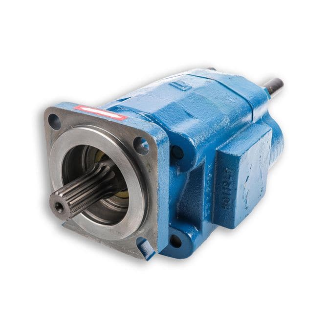
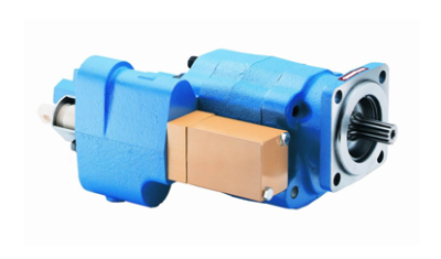
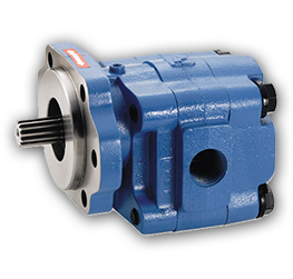
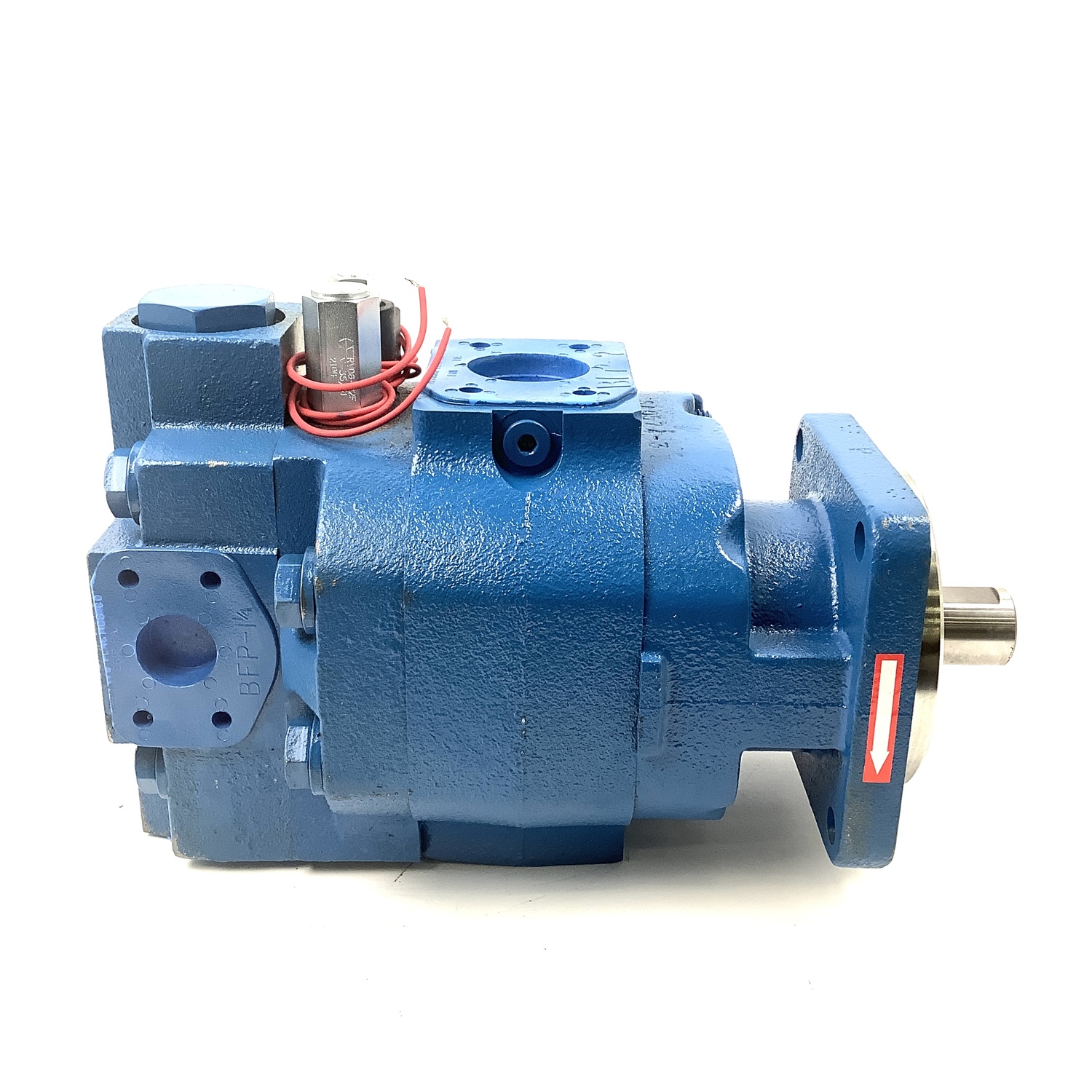
The P7500 / 7600 series gear pump is built from cast iron ensuring a strong and long lasting product, which can stand the most robust applications. Single & multiple units are available as per your requirements.
We machine, build from stock and test the P7500 / 7600 gear pump on site, to ensure the highest quality and a workable product is delivered to you. The P7500 / 7600 gear pump also comes with a 12 month warranty.
The P7500 / 7600 can be supplied as an ATEX gear pump if required. ATEX Group I & II approval is required, if the product will be used in potentially explosive atmospheres.
186 permco hydraulic pump parts products are offered for sale by suppliers on Alibaba.comAbout 3% % of these are hydraulic pumps, 1%% are construction machinery parts, and 1%% are other construction machinery attachments.
A wide variety of permco hydraulic pump parts options are available to you, You can also choose from gear pump, permco hydraulic pump parts,as well as from 1 year, 6 months, and 3 months permco hydraulic pump parts,And whether permco hydraulic pump parts is fittings, {2}, or {3}.
The 1000 and 2000 Series PTO"s have been engineered to work with the most common transmissions in today"s market. Offered in a wide range of input gear, ratio, output, and shifter options, these cast iron PTO"s include large 12mm flange bolts, which make for a very sturdy and durable pump mount, supporting some of the larger pumps in the market. Both of these models are also available in a deep mount 1010 and i2010 series. All Bezares PTO"s are built with the highest quality bearings and sealing components available.
The SP20B pump now utilizes self-lubricating thrust blocks that eliminate the need for seperate wear plates. They are made from a high strength aluminum alloy with exceptional anti-galling properties. This new thrust block design also incorporates advanced bearings designed specifically for high pressure hydraulic pumps. This new bearing features a robust fluoropolymer PTFE wear surface that yields unsurpassed load carrying capabilities and cavitation resistance even at low speeds and moderate levels of contamination. Also, since the PTFE resin layer is self-lubricating, contamination from bearing wear in high load situations (when no oil film is present) is reduced. This new thrust block design combined with these advanced bearing results in lower friction and less internal oil loss resulting in higher pump efficiencies.
Patented Non-Symmetrical Gears - The adoption of non-symmetrical gears insures greater power per unit volume compared with pumps of conventional design. The compact gear has enabled high-pressure operation. The increased number of gear teeth has reduced the flow pulsation and minimized the noise.
The Versa-pak Flow Control/Unloader unit is ideal for most residential and commercial refuse hydraulic systems. Applications include residential and commercial front loaders, rear loaders, automated side loaders, compactors, roll-offs, recycle and all PTO driven pump applications.
The 1000 and 2000 Series PTO"s have been engineered to work with the most common transmissions in today"s market. Offered in a wide range of input gear, ratio, output and shifter options, these all cast iron PTO"s include large 12mm flange bolts, which make for a very study and durable pump mount, supporting some of the larger pumps in the market. Both of these models are also available in a deep mount 1010 and i2010 series. All Bezares PTO"s are built with the highest quality bearings and sealing component available.
The SP25A pump now utilizes self-lubricating thrust blocks that eliminate the need for seperate wear plates. They are made from a high strength aluminum alloy with exceptional anti-galling properties. This new thrust block design also incorporates advanced bearings designed specifically for high pressure hydraulic pumps. This new bearing features a robust fluropolymer PTFE wear surface that yields unsurpassed load carrying capabilites and cavitations resistance even at low speeds and moderate levels of contamination. Also, since the PTFE resin layer is self-lubricating, contamination from bearing wear in high load situations (when no oil film is present) is reduced. This new thrust block design combined with these advanced bearing results in lower friction and less internal oil loss resulting in higher pump efficiencies.
Patented Non-Symmetrical Gears - the adoption of non-symmetrical gears insures greater power per unit volume compared with pumps of conventional design. The compact gear compartment has enabled high-pressure operation. The increased number of gear teeth has reduced the flow pulsation and minimized the noise.
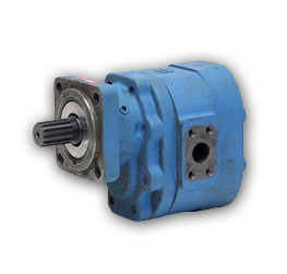
We carry the following Permco Series Numbers for Sleeve Bushing Pumps: P124, P197, P257, and P360. Click on the "details" button to see a list of specifications for each series.
The 3000 Series PTO is designed for the Allison AT/MT/HT model transmissions. This PTO has a low profile housing for easier mounting and is available with various outputs, ratios as well as either electric over hydraulic or air shift options.
Identifying your pump is the first step in replacing it or knowing which repair parts match your pump model. Many customers call us looking to replace their pump but they’re not sure which pump model they have or even who their pump’s manufacturer is. Luckily, your pump has all this information printed on it.
To identify the model of your pump, you need to know the part number. Part numbers, also sometimes referred to as model numbers, can be found on your pump’s tag. A pump tag is a small rectangular plate that displays all the basic information about your pump. Besides a pump’s part number, pump tags can include information like the gallons per minute, total dynamic head, and max working temperature of a pump. The information included on the tag is going to depend on the manufacturer of the pump.
Different types of pumps have their tags in different places. Finding the pump tag is sometimes half the battle. They are usually located on the volute of the pump (or the main body of the pump- the part that’s not the motor). Once you find your pump’s tag, the next step is, understanding what the information on that tag means exactly. If you can’t find your pump’s tag or if the numbers have faded or are hard to read, consult your owner’s manual or other paperwork that came with your product. Most product manuals will indicate where to find the model number.
Different manufacturers label their pumps differently. For example, some of the information printed on the Grundfos tag below might not appear on another brand’s pump or it can be referred to differently. This can be confusing at first so it helps to know who your pump’s manufacturer is and how they refer to their models. Some manufacturers print their logo on the pump.
You might see another similar looking plate on your pump. This is the pump’s motor tag. The motor tag gives information about the motor attached to the pump such as volts and phases. While the pump tag is usually located on the pump’s volute, the motor tag is located on the pump’s motor.
If the tag is missing, try to locate the casting number. Casting numbers are stamped directly in the steel/iron or bronze of the pump. These numbers are a good source of information about the unit.
This is a Bell & Gossett in-line circulator pump tag. The pump tags for these B&G circulators are generally easy to spot on the volute on the pump. On this Bell & Gossett In-Line Circulator pump, we can see the part number is
This next pump is a Zoeller sewage pump. The silver tag is located on the top of the pump. This tag gives us a little more information about the pump.
Nothing in life lasts forever. Luckily PumpProducts.com stocks a wide variety of repair parts for all the most trusted brands in the industry. If you’re not sure of your pump’s manufacturer, series, model number, or can’t find the parts you’re looking for, you can1-800-429-0800 and they’ll help you identify your pump and get you the parts you need. PumpProducts.com is your pump, parts, accessories and motor one-stop-shop.
Wear, Checking parts for...................................................................................................3 Thrust Plates.....................................................................................................................3 Diverter Plates, Installing PERMCO...................................................................................3 Bearings; Checking for wear..............................................................................................3 Gear Housing, checking for wear.......................................................................................3 Covers, Shaft-end and port-end: Checking for wear...........................................................3 Types of PERMCO Pumps: Type I, II..................................................................................3 Exploded Views: PERMCO Pumps and parts..................................................................4-6 Parts numbers, PERMCO Pumps and Motors....................................................................7 Type I Pump: disassembly..................................................................................................8 reassembly...............................................................................................12 Type II Pump: disassembly.................................................................................................8 reassembly........................................................................................................12 Torques for reassembling, Table of...................................................................................15 Trouble Shooting; List of symptoms and cures.................................................................17 Motors, PERMCO Pumps used as ...................................................................................18 Parts, How to order PERMCO replacement; information needed......................................19
If you intend to rebuild a pump that has thrust plates and you wish to replace the thrust plates with Permco diverter plates, inspect the original port end cover, shaft end cover, gear housing and bearing carriers very carefully. To obtain the maximum performance from diverter plates, all of the above components must be in good condition with minimal amount of wear. The following areas of wear are the most critical. . and often overlooked: 1. Shaft end covers, port end covers, and bearing carriers. . .Check bearing bores for out-of roundness or elliptical shape. If more than 0.003" out-of-round, do not use. 2. Gear housings... If the wear pattern on the inlet side is in excess of 0.003" depth, do not use. 3. Gears... Inspect very carefully. If you have scored, scuffed or pitted journals, scratched or scuffed tooth faces, deep nicks on tooth edges, do not use; install new drive and driven gear. 4. Bearings... A loose fit between gear hub and bearing ID may not mean a bad bearing. The misalignment it can cause is detrimental to good pump performance. We recommend installing a complete set of new bearings at each rebuild. 5. Seals. . .It is recommended that all seals be replaced on any rebuild job. Putting Permco diverter plates into a pump and reusing the old worn parts will not necessarily restore the pump to the high efficiency and performance of a new Permco pump. Merely installing new Permco diverter plates cannot restore the pump to its original performance. Permcos high efficiency, performance, and life expectancy are based on using all new PERMCO parts. 3
If you are rebuilding a Permco gear pump, you must not install thrust plates of another make. Tolerances and finishes on Permco parts are held closer than those of other manufacturers of pump parts. For warranty repairs under any circumstances, you must not substitute other makes of parts in a Permco pumps. USE ONLY GENUINE PERMCO PARTS. You can successfully use Permco diverter plates to rebuild other makes of pumps to obtain increased operating pressures and pump life. However, read the above paragraphs carefully. If you have any questions about rebuilding Permco pumps or about using Permco parts to upgrade other makes of pumps, call your local Permco pump and parts distributor.
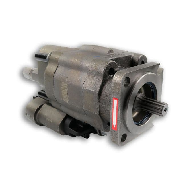
TWO TYPES OF PUMPSThere are two types of Permco pumps as determined by the configuration of the shaft end covers... Type I & Type II. There are slight differences in disassembly and reassembly procedures, according to each shaft end cover. Also Type II is normally shorter from front to back than Type I. This is because no outboard bearing is used. Be sure you know which type you are working on.
CLEANLINESS IS HIGHLY IMPORTANTWARNING. Before you start disassembling the pump, clean up your work bench. This will avoid the headaches and danger of getting dirt, metal fragments, and foreign objects into the fine-finished cavities and threads of the pump and components, and eventually into the entire hydraulic system. In pump maintenance, extreme cleanliness is most important.
PARTS LISTItem No. On Drawing Description Part Number Item No. On Drawing 16 Description Part Number 3000 SERIES PUMPS/MOTORS 1 2 3 4 5 6 7 8 9 10 11 12 13 14 15 16 17 18 19 20 21 22 23 24 25 26 28 Snap Ring Outboard Bearing Double Lip Seal Bearing Carrier Seal Retainer High Pressure Seal Shaft End Cover (SEC) Check Valve Assembly Continental Shaft Spacer Snap Ring Pump Shaft Seal Motor Shaft Seal Ring Seal Crowned Roller Bearing Thrust Plate (TP) Teflon Coated Thrust Plate Diverter Plate Gasket Seal Housing Drive Shaft & Gear Set Port End Cover 5/8" Grade 8 Washers 5/8-11 Grade 8 Threaded Rod 5/8-11 Grade 8 Hex Nut Bearing Carrier Connecting Shaft Gear Set Grade 8 Hex Head Cap Screw W023-206 W58-39 W62-26-16 UA-0558-2 ZD-0558 W62-49-9 ** - 0574- * L-0280-K ** -0024 SA-0558 W86-100 W62-26-18 W62-49-11 KA-0558-1XS X-0921 ZZ-0947 ZZ-0947-TC ZZ-0947-DS TA-2995-242 QZ-0577- ** - ** ** -0024L- * - ** WZ-0592- * W033-2 ZD-0391- *** W3-65 ** -0576- ** - *** YZ-0022 U-0996L- ** W1- ** Thrust Plate (TP) Teflon Coated Thrust Plate Diverter Plate Bi-Rotational Diverter Plate Gasket Seal Housing Drive Shaft & Gear Set Port End Cover (PEC) 5/8" Grade 8 Washers 5/8-11 Grade 8 Threaded Rod 5/8-11 Grade 8 Hex Nut Bearing Carrier Connecting Shaft Gear Set Grade 8 Hex Head Cap Screw X-0947 X-0947-TC X-0947-DS X-0947-BRD TA-2995-244 LZ-0577- ** - ** ** -0024L- * - ** YZ-0592- * W033-2 ZD-0391- *** W3-65 ** -0576- ** - *** XZ-0022 LZ-0995L- ** W1- **
7500 SERIES PUMPS/MOTORS 1 2 3 4 5 6 7 8 9 10 11 14 15 16 17 18 19 20 21 22 23 24 25 26 27 28 Snap Ring Outboard Bearing Double Lip Seal Bearing Spacer Seal Retainer High Pressure Seal Shaft End Cover (SEC) Check Valve Assembly Continental Shaft Spacer Snap Ring Ring Seal Crowned Roller Bearing Teflon Coated Thrust Plate Diverter Plate Bi-Rotational Diverter Plate Gasket Seal Housing Drive Shaft & Gear Set Port End Cover (PEC) 5/8" Grade 8 Washers 5/8-11 Grade 8 Threaded Rod 5/8-11 Grade 8 Hex Nut Bearing Carrier Connecting Shaft Gear Set O-Ring Grade 8 Hex Head Cap Screw W85-315 W58-48 W62-26-10 UA-0558 QZ-0961 W62-49-1 ** -0574- * L-0280-K ** -0024 ZE-0558 W86-137 VA-0558-1XS Q-0921 AZ-0947 AZ-0947-DS AZ-0947-BRD TA-2995-252 RZ-0577- ** - ** ** -0024L- * - ** XZ-0592- * W033-2 ZD-0391- *** W3-65 ** -0576- ** - *** ZA-0022 OZ-0995L- ** K-2995-164 W1- **
5000 SERIES PUMPS/MOTORS 1 2 3 4 5 6 7 8 9 12 13 14 15 Snap Ring Outboard Bearing Double Lip Shaft Seal Bearing Spacer Seal Retainer High Pressure Seal Shaft End Cover (SEC) Check Valve Assembly Continental Shaft Pump Shaft Seal Motor Shaft Seal Ring Seal Crowned Roller Bearing W023-283 W58-47 W62-26-17 UA-0558-1 ZB-0558 W62-49-8 ** -0574- * L-0280-K ** -0024 W62-26-17 W62-49-8 MA-0558-1XS R-0921
1. With a sharp metal scribing tool, grease pencil, Magic Marker, or paint, make an indexing mark that runs straight across a surface of the port end cover (20), gear housing (18), and shaft end cover (7). This will enable you to reas-semble these parts into the same position when you put the unit back together. 2. Clamp the unit in a vise, shaft end down. 3. Remove the cap screws or threaded rod (22) and washers (21) at the rear of the unit that hold the port end cover (20) and the gear housing (18) together. Remove the port end cover (20) and diverter plate (16) or thrust plate (16). The roller bearings (15) will remain with the port end cover (20). On those units with thrust plates, the pocket seals will come out easily. (Permco pumps having diverter plates do not require pocket seals.) 4. Remove the pump drive gear, the driven gear, and the gear housing (18) from the shaft end cover (7). BE CAREFUL to keep the drive gear and the driven gear together; you must reassemble them as the original pair, since they have been worked-in together.
1. If unit is equipped with a shaft bearing (2) or spacer (4), set the partially disassembled unit (shaft end cover (7)) from which the gear housing was separated in a vise with the pilot end up. If unit is a Type II, it cannot befitted with a shaft bearing (2) or spacer (4). Skip Step 2 below, and proceed to Step 3. 2. Remove the snap ring (1) from the shaft end cover (7). If a bearing is present, pull it out with a bearing puller; (this is not a press fit.) In units used as motors, a bearing (2) or bearing spacer (4) should be removed. Then remove the seal retainer (5). 3. Turn the shaft end cover into pilot-down position to make diverter plate (16) accessible. 4. Using a knife blade or thin-blade screwdriver pry the diverter plate (16) very gently off the bearings of the shaft end cover (7). Bearings should remain in cover. If they dont, or can be removed by hand, discard cover. If working on another make of pump to be refitted with PERMCO diverter plates, remove the pocket seals and throw away; on PERMCO Pumps, no pocket seals are required.
5. If you plan to replace the bearings, use a bearing puller to pull the roller bearings (15) out of the shaft end cover. If you do pull the bearings, check the bores for out-of round and elliptical shape. If out-of-round is over 0.003", DO NOT RE-USE. 6. Examine ring seal (14); if worn, replace. Do this by pulling the drive gear bearing. 7. Remove lip seal (3, if pump; 6, if motor) by inserting a curved tool between the seal and shaft end cover (7). Tap out seal and discard.
1. Set the partially-disassembled unit (shaft end cover 7) from which the gear housing has been separated in the vise, pilot-end up. 2. Remove the snap ring (1) from the shaft end cover (7). The bearing (2) or bearing spacer (4) can now be removed. It is a slip fit. A bearing puller can be used, if necessary. 3. Remove the seal retainer (5). Discard the Oring (27). 4. Remove the seal by inserting a curved tool between seal and seal retainer (5), tapping it out, and discarding. 5. Turn shaft end cover (7) pilot-end down in vise. Diverter plate will now be accessible. 6. With a knife blade or thin-blade screwdriver, Very Gently pry diverter plate (16) off the bearings of the shaft end cover (7). If working on another make of pump to be refitted with PERMCO diverter plates, remove the pocket seals and throw away. PERMCO pumps and diverter plates require no pocket seals. 7. Use a bearing puller to pull the roller bearings
of the shaft end cover (7), if you plan to replace bearings. If you pull the bearings, check bores for out-of-round condi-tion and elliptical shape. If more than 0.003" out-ofround, do not use again. 8. Examine the ring seal (14). Replace if worn by pulling the drive gear bearing. Type C pump has a separate shaft-and-gear set. Disassembly of Type C (Continental) Shaft End Cover Follow the steps described above for the standard shaft end cover. However, on the Type C unit, the shaft (9) will be pressed out of the cover (7) along with the bearing (2). Separate the shaft (9) from the bearing (2) as follows: 1. Remove snap ring (11) and spacer (10) from gear end of shaft (9). 2. Press bearing (2) off gear end of shaft (9).
Remove square gasket seals (17) from gear housing (18), and discard. Have identical replacements at hand for reas-sembly. DO NOT USE O RINGS. Check for depth of wear in gear housing at this time; use a telescoping gage and a micrometer. If wear pattern on gear housing exceeds 0.003", discard housing and replace with a new one. Figure A shows a satisfactory housing with little wear. Figure B shows a housing with excessive wear; notice large cavities that indicate cavitation was present. Examine the housing for cracks (Figure C). Thisis caused by overpressure or by possible over tightening of an NPT thread. If a new gear housing is required and a large port is present, step-drill the housing (Figure D) if PERMCO diverter plates are to be installed. 2. Examine gears for wear, scuffed or pitted journals, scratched or scuffed tooth faces, or deep nick on tooth edges. If any of these defects are present, install new drive and driven gears. Figure E shows a satisfactory gear hub, with no nicks. Figures F and G show gear hubs that are breaking down from contamination, overpressurization, pressure shock, or bearing failure. On examination of gear faces, some scratches may be found; if they can be removed by stoning, the set can be reused (see Figures H and I). Also examine the ring seal surface (Figure J) for wear. Figure K shows a rotating group that ran without oil.
Port End Cover1. Use a knife blade or thin-blade screwdriver to gently pry the diverter plate (16) or the thrust plate off the bearings (15) of the port end cover (20). 2. When working on pumps other than PERMCO Pumps, remove and discard the pocket seals. When installing PERMCO diverter plates, you do not install replacement pocket seals; PERMCO Diverter Plates do not require pocket seals. 3. If you plan to replace the two shaft roller bearings (15) with new ones, pull the bearings (15) out of the port end cover (20) with a bearing puller. 4. Examine the ring seal (14). If worn, replace by pulling the drive gear bearing (15) out, leaving the driven gear bearing (15) in place. Examine all diverter or thrust plates. Some wear will always appear, because of gear flexing. Figure L indicates very slight wear, with some scratches because of contamination. Figure M shows wear in the trapping area caused by contamination. In bi-rotational units where there are two trapping grooves, a diagonal groove may develop connecting the two slots. This is caused by contamination. Figure N shows the effect of cavitation... the rapid forma-tion and collapse of vapor cavities within a fluid. This effect is caused by high-vacuum inlet conditions or by air enter-ing the pump inlet.
3000/5000 Series Pumps:Reassembly of Shaft End Cover:1. Grip shaft end cover (7) gear end up. Place ring seal (14) in bearing bore of shaft end cover (7) with the flat side down. 2. Replace the two roller bearings (15) in the bores of the shaft end cover (7). Take care that the bearings do not cock or wedge between ring seal (14) and bottom of bearing counter-bore. 3. Place shaft end cover (7) in a soft-jaw vise. Turn cover (7) end-for-end, and clamp with flange end up. 4. Apply Loctite Adhesive Sealant No. 271 to outside of seal (3, 6, 12, or 13). Press seal into shaft end cover (7) until seal is flush with counter-bore. If working on a Type I pump, which has no outboard bearing, or a Type II pump, assem-bly of shaft end cover is now complete. If working on Type I unit having bearing or bearing spacer and integral gear shaft continue as follows: 5. In motors only, insert the seal retainer (5) into the shaft end cover (7). 6. Guide the bearing (2) or bearing spacer (4) into the shaft end cover (7). This is NOT a press fit. 7. Install snap ring (1) into the groove. Reassembly of shaft end cover (7) is now complete.
Continental ShaftsFor Type I pumps with C Type shafts, follow the above steps 1 through 4; then proceed as follows: 5. Push seal assembly into shaft end cover (7) with seal on inboard side. 6. Press the outboard bearing (2) on the drive shaft (9) from the gear end. 7. Push spacer (10) over the end of the shaft (9). Install snap ring (11) in the groove on shaft (9). 8. Press the bearing (2) and spacer (10) tightly against the snap ring (11). 9. Lubricate the drive shaft (9), and put this assembly into the shaft end cover (7). Be careful not to damage the seal. 10. Install the snap ring (1) in the groove. The shaft end cover reassembly is now complete.
1. If you removed the two roller bearings (15) or the ring seal (14) during disassembly, install new bearings (15) and ring seal (14) in the portend cover (20). Place the ring flat side down in the drive gear bearing bore, and make a medium press fit. 2. Place the diverter plate (16) over the two roller bearings (15). The counter-bored side of the diverter plate (16) should be placed over the bearings (15) with the high-pressure crescent recesses toward the pump inlet side. Doublecheck the placement of the diverter plate (16) for correct positioning.
1. If you. removed the four roller bearings (15) or ring seals (14) during disassembly, install new bearings (15) and ring seals (14) in the bearing carrier (24). Place the ring seals (14) flat side down in the drive gear bearing bore and press bearing with a medium press fit. 2. Place the diverter plate (16) over the two roller bearings (15). The counter-bored side of the diverter plate (16) should be placed over the bearings (15) with the high-pressure crescent recesses on the pump inlet side. Double- check the placement of the diverter plate (16) for correct positioning.
1. Clamp the shaft end cover (7) assembly in a soft jaw vise, gear end up. 2. Place the diverter plate (16) over the two roller bearings (15). The counter-bored side of the diverter plate (16) should be placed over the bearings (15) with the high-pressure crescent recesses on the pump inlet side. Double -check the placement of the diverter plate (16) for correct positioning. 3. Pour a little hydraulic, STP or a compatible fluid over face of diverter plate (16) to lubricate gears immediately on start-up. Gently stone the sides of each gear (119 and 26) to remove any burrs. Dip entire gear into cleaning solvent to remove all dirt and metal dust. Install drive gear first, then the driven gear. Be sure both gears are firmly in contact with diverter plate. 4. Lightly grease square gasket seals (17) and carefully install them in the grooves in the two faces of the gear housing (18). Be sure they are fully seated. 5. Carefully place the gear housing subassembly over the gears, on top of the shaft end cover (7). Make sure the square gasket (17) is not pinched or cocked, then tap the gear housing (18) down on the shaft end cover (7) with a
soft mallet. Pour a little fluid over the gears while rotating the drive shaft. This will provide immediate lubrication when starting up pump. (If the unit is a single one, skip Step 6 and go to Step 7.) 6. Position the assembled bearing carrier over the gear jour-nals and gently tap it into place. Be sure the high-pressure crescents of the diverter plate (16) are positioned towards the pump lowpressure side. Install the connecting shaft. (25) Repeat Steps 3 through 7, above, until you attach the final gear housing (18). Then pick up at Step 7, below. 7. Place the port end cover (20) over the gear hubs (19) and place in gear housing (18), face down. The drive gear has longer bearing hubs to engage the ring seal. Tap the port end cover (20) assembly gently down on the housing (18) with a soft mallet. Be sure the square gasket (17) is not pinched or cocked. 8. Put flat washers (21) over cap screws (22), or use Grade 8 threaded rod. Place screws or threaded rod in holes in port end cover (20). Tighten evenly and alternately with a torque wrench to recommended torque shown in table. Recommended torque for pumps and motors Series Size No. Req. Torque Lb.ft. 5/8-11 3000/5000 UNC-2A 4 200 Thread 5/8-11 7500 UNC-2A 8 200 Thread Note: All bolts or tie rods must beSAE Class 8, with 150,000 PSI minimum tensile strength. 9. Test the assembled pump for free rotation by turning drive shaft by hand, using a wrench for leverage. Caution: Wrap several layers of cloth around shaft ends before applying wrench. The shaft should turn with slight effort, NO hard spots and NO rubbing noises. If your pump or motor is a 3000/5000 or 7500C series, it is ready to put back in service. But if it is a standard 7500 series unit, and you did not install the bearing and snap ring earlier, proceed to the following steps before putting it in service: 10. Release the unit from the vise and turn endfor-end so that the shaft end is facing up. Reclamp unit in vise. 11. Install bearing (2) or bearing spacer (4). This is a slip fit over the shaft (9) and into shaft end cover (7). 12. Install the snap ring (11) into groove. Your standard 7500 series unit is now ready to put back in service.
FOLLOW THESE INSTRUCTIONS CAREFULLY. If you dont, you can instantly ruin your pump if the relief pressure setting is too high. 1. Before you operate the pump, unscrew the main relief valve adjusting screw on the main hydraulic system. OR remove adjusting shims or spacers. 2. Run the pump about five minutes under ZERO PRESSURE , with all control valves in neutral position. If the test system has a throttling valve, set it at 100 psi. above users expected operating pressure. 3. If everything seems to function properly and no unusual noises are heard, back-off the throttling valve to zero. Shut down the system. 4. Adjust the relief valve pressure to the setting your hydrau-lic system requires.
LUBRICATION OF PERMCO PUMPS1. The hydraulic oil used in the entire circuit provides the lubrication for all parts of the pump. KEEP T H I S O I L CLEAN AND FREE OF DIRT. PERMCO recommends a 25-micron return filter and a 149-micron (100-mesh screen) suction filter to fully protect the pump and system from excessive wear and damage from dirt. 2. If the pump fails and you think metal particles have gotten in the circuit: a. Drain ALL oil from the whole system, b. Flush the system with kerosene, c. Refill the system with fresh oil of correct grade, (These are correct oils: Viscosity index at 100F (37C): 90 or higher; Viscosity SUS at 100 F (37 C): 150 to 300 (32-65 CST); Aniline point: 165 or higher; Anti-foam and anti-oxidant additives.) 3. Temperature of oil should never exceed 185F (85 C.) 4. NEVER use low-viscosity naphtha-base oils, aircraft hydraulic fluids, or automotive brake fluids without con-sulting PERMCO, INC. o r a Permco distributor. 5. For extended operation at temperatures below 20 F (-7 C) always use a low-pour-point oil of top quality.
TROUBLE SHOOTINGREMEDY PROBLEM REMEDYReplenish fluid to proper level, with proper grade Drain system and refill with specified grade of fluid Clean or replace filter element Install larger suction line Clean line thoroughly Check pump maximum speed; Slow down pump driver; Or install larger pump Clean or replace breather on reservoir Drain system and refill with nonfoaming hydraulic fluid Replace with larger filter Realign flexible coupling between pump and driver Drip oil over suspected joint; listen for change in sound of pump; tighten joints Replace parts as necessary Relief valve leaking Pump fails to prime itself a. Air leak into suction line b. Oil is too heavy c. System not in Neutral Pump rotating in wrong direction IMMEDIATELY STOP PUMP DRIVER to prevent damaging pump. Then reverse direction of pump rotation Tighten up joints. Drain system and replace fluid with proper grade of anti-foaming fluid Open valve on pressure side of pump, or install air bleed valve
SYSTEM LACKS ANY PRESSURE WITH PUMP RUNNING:Relief valve not set correctly Use pressure gauge and reset valve to specified pressure Check relief valve seat for score marks. Reseat by grinding. Or replace. Replace spring; reset relief valve Check for control valve in Neutral or for open return line Repair or replace leaking valve or cylinder
EXCESSIVE WEAR IN PUMP:Abrasive contaminants in fluid Drain and flush entire system. Install new filter. Fill system with fresh oil of proper grade or filter con-taminated oil through a 10-micron filter before refilling. Operate pump an hour. Drain system again. Install new filter element and fluid. Drain and replace with anti-foaming fluid of proper grade. Check and reset relief valve pressure, using pressure gauge.
PROBLEMSustained excessive speed at pressure above pump maximum rating Drive misalignment; Tight belt; weight of pump supported by its drive shaft Entrapped air in hydraulic system
REMEDYRecheck pump rated speed. Slow down driver to produce this speed. Check pump/driver coupling or belt alignment. Install adequate support for pump. Bleed air from hydraulic system
Erratic pump performance: a. Drain system and refill with lighter grade antia. If pump runs slow on foaming fluid. startup, and speeds up after fluid is warm, fluid fluid grade is too heavy. b. If pump slows down after fluid has heated up, fluid is too light b. Drain system and refill with heavier grade anti-foaming fluid.
OVERHEATED FLUID:Fluid too heavy Drain system and refill with lighter grade of anti-foaming fluid. Drain system and refill with heavier weight anti-foaming fluid. Drain and flush system; refill with proper grade of antifoaming fluid; replace filter element. Disassemble relief valve and remove contaminant. Check condition of filter to prevent recurrence. Use gauge and adjust relief valve setting to cor-rect pressure Repair worn pump parts or replace pump. Repair or replace relief valve Disassemble pump and back off over-torqued component to tightness specified in this maintenance manual Replace with proper size hose and valves Re-plumb system eliminate restrictions to
MOTOR DOESNT DEVELOP PROPER TORQUE OR SPEED(when pump is used as a motor)Relief valve incorrectly adjusted Relief valve sticking open Use a pressure gauge and increase relief valve pressure setting to proper level Disassemble relief valve and remove dirt from under ball or piston. Check condition of filter to prevent recurrence. Check for control valve in Neutral or for open return line. Use pressure and flow gauges to check pump out-put and pressure. Realign belt drive or coupling, recheck torque requirements of pump for maximum input.
Incorrect setting on relief valve Worn pump permits oil to bypass internally Relief valve leaks or not operating Excessive friction caused by pump components overtorqued Undersize hoses and valves in system Restrictions and excessive bends in lines Inadequate reservoir prevents adequate cooling of fluid Internal leaks not in pump
(when pump is used as hydraulic motor)If you have used a standard control valve to control a hydraulic motor, serious and catastrophic harm can result. When the standard control valve is returned to Neutral, to start or stop the motor sudden excessive pressure develops. This pressure can burst seals, fracture drive shafts, burst housings, and rupture hoses.
PUMP NOT EFFICIENT:Worn pump parts reduce pump efficiency Air in system Repair or replace pump Bleed air from system; check line connections for air leaks
HOW TO ORDER PARTSALWAYS GIVE US THE SERIES NUMBER, please. It instantly tells us what PERMCO Pump or Motor you want parts for. You will find this Series Number on the nameplate. IF YOU CANNOT SUPPLY THE SERIES NUMBER, Please answer these questions: 1. Is the unit a pump or a hydraulic motor? 2. If a pump, which way does it rotate when you look at it from the shaft end? Clockwise? Or Counter-Clockwise? 3. How many gear housing sections does the unit have? 4. Check Series Identification Table below to determine series. STEPS IN IDENTIFICATION: 1. Shaft end cover: Mounting flange: Is it pad mounting or foot mounting? How many bolts, 2, 4, 6, 8? If round flange, measure pilot diameter, center diameter, and bolt-hole diameters. 2. Bearing arrangement: With or without outboard bearings? Double outboard bearings? Bearing measurements? Any drains or grease fittings? 3. Drive shaft: Diameter of shaft end? Keyed or not? Length of spline? Number of spline teeth O.D.? Total length of shaft? 4. Housing: Width of housing? Inside diameter of ports? 5. Port end cover: Inside diameter of ports? 6. Bearing carrier: Inside diameter of ports? Direction of flow thru internal passage or coring? 7. Gears: Gear tooth width? Gear O.D. measured over teeth? If gears are integral, describe drive end of drive gear, as in Paragraph 3 above.
* Continental (Two-Piece Drive Shaft & Gear Set) available on Series 3000, 5000 and 7500 as specials; consult factory.19Copyright 2006 Permco Bulletin # 06-305075A
Permco is a leading manufacturer of high-pressure hydraulic gear pumps and motors, flow dividers, intensifiers, and accessories. Both roller bearing and sleeve bushing series are available in a wide variety of sizes and configurations.
Starting as the Perfection Machining Company in 1964, Permco hydraulic pumps began designing and manufacturing replacement parts for the mining industry. In 1968 the name was officially changed to Permco and the development of replacement hydraulic parts was under way.
In 1974 Permco hydraulic pumps expanded its manufacturing capabilities to include cast iron parts, which enabled us to offer complete units. We later developed our sleeve bushing pumps, which have recently been rounded out with the introduction of the P124 series.
Permco, working with The Torrington Company, developed the patented "controlled stress" roller bearing, which increases pump and motor life by up to 30%. As a result, we recently extended our warranty from one year to two years.
Our commitment is to continue to develop and offer the highest quality product possible to our wide customer base, which includes both OEM"s and distribution. We are also committed to working with our customers to supply them in such a way as to reduce their cost and to make their interface with Permco hydraulic pumps as seamless as possible. We are determined to do business the old fashioned way, while incorporating as much technology as makes sense to keep up with today"s fast pace in business.
At Northern Hydraulics we manufacture your Permco Hydraulic Pump on-site in our full service Machine Shop.Permco products are available in a variety of sizes and configurations to meet your specific needs. Give us a call at 1-800-823-4937, we have the Permco hydraulic components to build you the Permco Hydraulic Pumps or Motors you need.


 8613371530291