
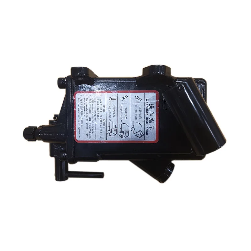
pickup hydraulic pump free sample
Low Pressure Hydraulics – Too much hydraulic power, especially on aluminum trailers, makes it that much easier to damage and poke holes in the trailer. Our Shuttle Probes can generate about 700 lbs. of down pressure, but from experience we have learned that 200 to 300 lbs. of down pressure more than enough to probe to the bottom of a semi hopper (see Automatic Sampling). Our hydraulic system pressure is set to a maximum of 750 psi compared to the 1200 to 1500 psi with other probes.
Self-Contained Design – All hydraulic, vacuum, and electrical components are located in the probe base. Beside being a cleaner design, it helps to protect the hoses & wiring from damage and weathering.
Low Pressure Hydraulics – Our Shuttle II Grain Probes can generate 700 lbs of down pressure, but from experience we have learned that 200 to 300 lbs of down pressure is more than enough to probe to the bottom of a semi hopper. Too much hydraulic power makes it that much easier to damage a trailer, and with aluminum trailers the problem is worse. Our hydraulic system pressure is set to a maximum of 750 psi compared to the 1200 to 1500 psi with other probes.
Air Craft Hydraulic Oil – Provides excellent cold weather operation and eliminates the need for a hydraulic tank heater. Food-grade hydraulic oil is optional.
Self-Contained Design – Most of the hydraulic, vacuum, and electrical components are located inside the probe base, mast, and boom for protection from sunlight, wind and weather.
Whether gear, vane, or piston pump, there may come a time when you have to replace your hydraulic pump. When your equipment isn’t working properly and you have narrowed the problem down to a hydraulic pump that needs to be replaced, what do you need to know?
The pump may simply be worn out—they do have a natural lifespan, as they are a wearable item in a hydraulic system. Although it is not possible to give an average lifespan given the different types of pumps and widely varying hours of operation; in general, you can expect many years of good operation from a hydraulic pump in most truck-mounted hydraulic systems. However, the life of a hydraulic pump might be much longer than what you are experiencing. Here are some questions you should ask:
Has the equipment been operating acceptably with this pump for a number of years without incident, and has the decline in performance been gradual over a longer period of time?
In this case, you’ll need to get the pump make and model number so that you can make sure that your replacement will be correct—either with an exact replacement or with another make that has the same operating specifications.
In any case, when replacing a failed hydraulic pump you will want to make sure to use this opportunity to also change out your hydraulic fluid (or at the very least use a filter cart and filter your oil). In the process of failing, your pump has introduced contaminants into your hydraulic system that you want to remove before they damage your new pump or any other hydraulic component. You will want to change your filter element(s) when you install your new pump, and then change it (them) out after a break-in period on your new pump.
If not, then let’s make sure there is not something else going on, or you may just find yourself replacing pumps frequently because the underlying problem hasn’t been addressed.
Input shaft is twisted/bcanroken: This occurs due to an extreme shock load to the pump. Typically, this happens when a relief valve is missing from the system, not functioning correctly, set to a much higher value than what the pump can withstand, or is too small for the system flow and thus cannot function correctly.
Shaft fretting:Fretting corrosion occurs under load in the presence of repeated relative surface motion, for example by vibration. Direct mount pump splines can be worn away. The solutions include:
Using larger pump and PTO shafts will not eliminate fretting, but may resolve the problem because of the increased metal available before the failure occurs.
Make sure that the pump is able to get a good flow of oil from the reservoir—pumps are designed to have the oil feed pushed to the pump by gravity and atmospheric pressure, not by “sucking” oil. If the oil level in the reservoir is lower than the inlet of the pump, or the run too long or uphill, oil may not flow adequately to the pump. You can check if the pump is receiving oil adequately by using a vacuum gauge at the pump inlet. For a standard gear pump, at maximum operating RPM, the gauge should read a maximum of 5 inches HG. Larger numbers will damage a gear pump, and if you have a piston pump, the maximum number will be lower for good pump life.
Over pressurization: Pressure relief settings may have been adjusted or changed, and are now higher than what the pump can withstand without causing damage.
Pumps don’t produce pressure, they produce flow and are built to withstand pressure. When the system pressure exceeds the pump design, failure begins—either gradually or catastrophically.
When installing the new pump, back all the relief settings off. Then with the use of a pressure gauge T’d in at the pump outlet, gradually adjust the pressure relief setting until a cylinder or motor begins to move. Once the cylinder has reached the end of its stroke, gradually increase the pressure relief setting until reaching the max system pressure (which would be the pressure rating of the lowest rated component in the system). Sometimes, if a pump has been replaced and is larger than the original (produces more flow), the relief may not be able to allow all the flow being produced to escape back to tank. When that happens, the relief valve is “saturated” and the effect is the same as having no relief in the system. Pressures can reach levels much higher than the relief settings and components can be damaged or destroyed.
Contamination: Over time, the system oil has gotten dirty or contaminated and no longer is able to lubricate the pump, or is carrying contamination to the pump.

Electrical– Power and ground connections will be routed directly to the battery Hydraulics – The hydraulic pump will be installed, fluid added to the reservoir and wired.
If you choose not to do the hydraulic dump kit installation yourself, we have found body shops and machine/welder shops typically have the expertise required. Basically, any shop installing flat beds has the expertise.

Check that the pump shaft is rotating. Even though coupling guards and C-face mounts can make this difficult to confirm, it is important to establish if your pump shaft is rotating. If it isn’t, this could be an indication of a more severe issue, and this should be investigated immediately.
Check the oil level. This one tends to be the more obvious check, as it is often one of the only factors inspected before the pump is changed. The oil level should be three inches above the pump suction. Otherwise, a vortex can form in the reservoir, allowing air into the pump.
What does the pump sound like when it is operating normally? Vane pumps generally are quieter than piston and gear pumps. If the pump has a high-pitched whining sound, it most likely is cavitating. If it has a knocking sound, like marbles rattling around, then aeration is the likely cause.
Cavitation is the formation and collapse of air cavities in the liquid. When the pump cannot get the total volume of oil it needs, cavitation occurs. Hydraulic oil contains approximately nine percent dissolved air. When the pump does not receive adequate oil volume at its suction port, high vacuum pressure occurs.
This dissolved air is pulled out of the oil on the suction side and then collapses or implodes on the pressure side. The implosions produce a very steady, high-pitched sound. As the air bubbles collapse, the inside of the pump is damaged.
While cavitation is a devastating development, with proper preventative maintenance practices and a quality monitoring system, early detection and deterrence remain attainable goals. UE System’s UltraTrak 850S CD pump cavitation sensor is a Smart Analog Sensor designed and optimized to detect cavitation on pumps earlier by measuring the ultrasound produced as cavitation starts to develop early-onset bubbles in the pump. By continuously monitoring the impact caused by cavitation, the system provides a simple, single value to trend and alert when cavitation is occurring.
The oil viscosity is too high. Low oil temperature increases the oil viscosity, making it harder for the oil to reach the pump. Most hydraulic systems should not be started with the oil any colder than 40°F and should not be put under load until the oil is at least 70°F.
Many reservoirs do not have heaters, particularly in the South. Even when heaters are available, they are often disconnected. While the damage may not be immediate, if a pump is continually started up when the oil is too cold, the pump will fail prematurely.
The suction filter or strainer is contaminated. A strainer is typically 74 or 149 microns in size and is used to keep “large” particles out of the pump. The strainer may be located inside or outside the reservoir. Strainers located inside the reservoir are out of sight and out of mind. Many times, maintenance personnel are not even aware that there is a strainer in the reservoir.
The suction strainer should be removed from the line or reservoir and cleaned a minimum of once a year. Years ago, a plant sought out help to troubleshoot a system that had already had five pumps changed within a single week. Upon closer inspection, it was discovered that the breather cap was missing, allowing dirty air to flow directly into the reservoir.
A check of the hydraulic schematic showed a strainer in the suction line inside the tank. When the strainer was removed, a shop rag was found wrapped around the screen mesh. Apparently, someone had used the rag to plug the breather cap opening, and it had then fallen into the tank. Contamination can come from a variety of different sources, so it pays to be vigilant and responsible with our practices and reliability measures.
The electric motor is driving the hydraulic pump at a speed that is higher than the pump’s rating. All pumps have a recommended maximum drive speed. If the speed is too high, a higher volume of oil will be needed at the suction port.
Due to the size of the suction port, adequate oil cannot fill the suction cavity in the pump, resulting in cavitation. Although this rarely happens, some pumps are rated at a maximum drive speed of 1,200 revolutions per minute (RPM), while others have a maximum speed of 3,600 RPM. The drive speed should be checked any time a pump is replaced with a different brand or model.
Every one of these devastating causes of cavitation threatens to cause major, irreversible damage to your equipment. Therefore, it’s not only critical to have proper, proactive practices in place, but also a monitoring system that can continuously protect your valuable assets, such as UE System’s UltraTrak 850S CD pump cavitation senor. These sensors regularly monitor the health of your pumps and alert you immediately if cavitation symptoms are present, allowing you to take corrective action before it’s too late.
Aeration is sometimes known as pseudo cavitation because air is entering the pump suction cavity. However, the causes of aeration are entirely different than that of cavitation. While cavitation pulls air out of the oil, aeration is the result of outside air entering the pump’s suction line.
Several factors can cause aeration, including an air leak in the suction line. This could be in the form of a loose connection, a cracked line, or an improper fitting seal. One method of finding the leak is to squirt oil around the suction line fittings. The fluid will be momentarily drawn into the suction line, and the knocking sound inside the pump will stop for a short period of time once the airflow path is found.
A bad shaft seal can also cause aeration if the system is supplied by one or more fixed displacement pumps. Oil that bypasses inside a fixed displacement pump is ported back to the suction port. If the shaft seal is worn or damaged, air can flow through the seal and into the pump’s suction cavity.
As mentioned previously, if the oil level is too low, oil can enter the suction line and flow into the pump. Therefore, always check the oil level with all cylinders in the retracted position.
If a new pump is installed and pressure will not build, the shaft may be rotating in the wrong direction. Some gear pumps can be rotated in either direction, but most have an arrow on the housing indicating the direction of rotation, as depicted in Figure 2.
Pump rotation should always be viewed from the shaft end. If the pump is rotated in the wrong direction, adequate fluid will not fill the suction port due to the pump’s internal design.
A fixed displacement pump delivers a constant volume of oil for a given shaft speed. A relief valve must be included downstream of the pump to limit the maximum pressure in the system.
After the visual and sound checks are made, the next step is to determine whether you have a volume or pressure problem. If the pressure will not build to the desired level, isolate the pump and relief valve from the system. This can be done by closing a valve, plugging the line downstream, or blocking the relief valve. If the pressure builds when this is done, there is a component downstream of the isolation point that is bypassing. If the pressure does not build up, the pump or relief valve is bad.
If the system is operating at a slower speed, a volume problem exists. Pumps wear over time, which results in less oil being delivered. While a flow meter can be installed in the pump’s outlet line, this is not always practical, as the proper fittings and adapters may not be available. To determine if the pump is badly worn and bypassing, first check the current to the electric motor. If possible, this test should be made when the pump is new to establish a reference. Electric motor horsepower is relative to the hydraulic horsepower required by the system.
For example, if a 50-GPM pump is used and the maximum pressure is 1,500 psi, a 50-hp motor will be required. If the pump is delivering less oil than when it was new, the current to drive the pump will drop. A 230-volt, 50-hp motor has an average full load rating of 130 amps. If the amperage is considerably lower, the pump is most likely bypassing and should be changed.
Figure 4.To isolate a fixed displacement pump and relief valve from the system, close a valve or plug the line downstream (left). If pressure builds, a component downstream of the isolation point is bypassing (right).
The most common type of variable displacement pump is the pressure-compensating design. The compensator setting limits the maximum pressure at the pump’s outlet port. The pump should be isolated as described for the fixed displacement pump.
If pressure does not build up, the relief valve or pump compensator may be bad. Prior to checking either component, perform the necessary lockout procedures and verify that the pressure at the outlet port is zero psi. The relief valve and compensator can then be taken apart and checked for contamination, wear, and broken springs.
Install a flow meter in the case drain line and check the flow rate. Most variable displacement pumps bypass one to three percent of the maximum pump volume through the case drain line. If the flow rate reaches 10 percent, the pump should be changed. Permanently installing a flow meter in the case drain line is an excellent reliability and troubleshooting tool.
Ensure the compensator is 200 psi above the maximum load pressure. If set too low, the compensator spool will shift and start reducing the pump volume when the system is calling for maximum volume.
Performing these recommended tests should help you make good decisions about the condition of your pumps or the cause of pump failures. If you change a pump, have a reason for changing it. Don’t just do it because you have a spare one in stock.
Conduct a reliability assessment on each of your hydraulic systems so when an issue occurs, you will have current pressure and temperature readings to consult.
Al Smiley is the president of GPM Hydraulic Consulting Inc., located in Monroe, Georgia. Since 1994, GPM has provided hydraulic training, consulting and reliability assessments to companies in t...
Dependable Hydraulics was founded in 1960 and started by two brothers, Ben and Frank La Rosa. It employed 2 people and had a 5,000 square foot facility in Lynbrook, Long Island. Today Dependable has grown to employ 35 people and has two locations.
Dependable Hydraulics repair, service and sell all types of hydraulic components, pumps, valves, motors, hydraulic winches, gear boxes, collectors, accumulators, steering boxes, cylinders, and many more. They also have a full machine shop at both locations that perform various types of machine work. They can machine off a blueprint, or as per your supplied sample.
Visit their showroom where they sell seals, components, and hose assemblies while you wait. Dependable Hydraulics provides free pick-up and delivery to your facility daily.
Dependable Hydraulics offer an open door policy to all their customers and encourage you to come down to their facility for an in-house tour. At this time you will be able to witness some of the work they perform, see their state of the art computer system, tear down procedures, full rebuilds and the final testing procedures on various components.

From the elevator you take at work to the dump truck you see rolling by on the street, hydraulics are everywhere. You may be wondering what hydraulics are. This powerful system drives some of the heaviest pieces of machinery out there. Hydraulics can lift immense loads and operate at high speeds. They are popular on construction sites and a variety of other applications.
There are many types of hydraulic systems with various components, all of which operate under the same principles of energy. Hydraulic pumps pressurize a liquid, and its movement is used to power everything from cranes to cars. In this article, we’re going to tell you everything you need to know about hydraulic systems.
You’re probably already familiar with some of the basic ways a hydraulic system works and its components. From your experience, you probably know that solids are typically impossible to squish. If you pick up a solid object like a pen or piece of wood and try to squeeze it, nothing’s going to happen to the materials. They won’t compress or squish. Liquid works in the same way. It is incompressible, meaning it won’t squeeze when you apply pressure to it. It takes up the same amount of space as it did when pressure wasn’t applied to it. Picture water in a syringe. If you cap the end of it with your finger and try to press down, neither the water nor the plunger will go anywhere.
Where hydraulic systems are concerned, that incompressibility is a major player in making them work. In that same syringe, if you press down on the plunger normally, you’ll release the water at high speed through the narrow end, even if you didn’t apply that much pressure. When you push down the plunger, you apply pressure to the water, which will try to escape however it can — in this case, at high pressure through a very narrow exit. This application shows us that we can multiply force, which we can then use to power more complex devices.
In a very simplified system, a hydraulic system is made with piping that has a weight or piston on one end to compress the liquid. As this weight depresses onto the liquid, it forces it out of a much narrower pipe at the other end. The water doesn’t squish down and instead pushes itself through the pipe and out the narrow end at high speed. This system works in reverse as well. If we apply a force to the narrow end for a longer distance, it will generate a force capable of moving something much heavier on the other end.
There is a little bit of a trade-off with this system. You can typically apply more force or more speed to one end to see the opposite result on the other. For example, if you press down on the narrow end with high speed and low force, you’ll apply high force but low speed to the wide end. The distance your narrow end can travel would also influence how far the wide one will move. Trading distance and force is typical in many systems, and hydraulics are no exception.
The multiplication of force is an influential factor in lifting heavy objects. If the piston in the broader side is six times the size of the smaller one, then the force applied to the fluid from the larger piston will be six times as powerful on the smaller end. For example, a 100-pound force down at the wider end creates a 600-pound force up at the narrow end. This force multiplication is what allows hydraulic systems to be relatively small. They are great for powering huge machines without taking up too much space.
Hydraulics can also be very flexible, and there are many different types of hydraulic systems. You can move the fluids through very narrow pipes and snake them around other equipment. They have a variety of sizes and shapes and can even branch off into multiple paths, allowing one piston to power several others. Car brakes are usually an example of this. The brake pedal activates two master cylinders, each of which reaches two brake pads, one for all wheels. You can find hydraulics powering a variety of components through cylinders, pumps, presses, lifts and motors.
Reservoir: Hydraulic systems usually use a reservoir to hold excess fluid and power the mechanism. It is important to cool the fluid, using metal walls to release the heat generated from all the friction it encounters. An unpressurized reservoir can also allow trapped air to leave the liquid, which helps efficiency. Since air compresses, it can divert the movement from the pistons and make the system work less efficiently.
Fluid: Hydraulic fluids can vary, but they are typically petroleum, mineral- or vegetable-based oils. The fluids can have different properties based on their application. Brake fluid, for example, needs to have a high boiling point due to the high-heat mechanism it goes through. Other features include lubrication, radiation resistance and viscosity.
Engine: This is usually gasoline-powered and allows the hydraulic system to work. In big machines, this needs to be capable of generating a lot of power.
Pump: The hydraulic oil pump sends a flow of oil through the valve and to the hydraulic cylinder. Pump efficiency is often measured in gallons per minute and pounds per square inch (psi).
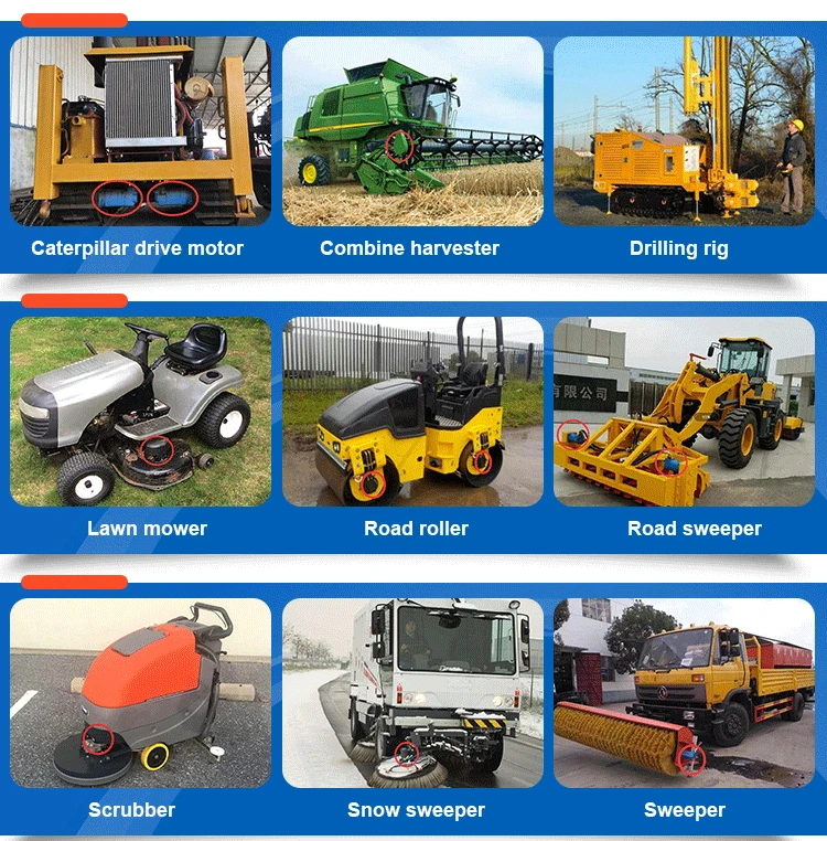
Other machines that make use of hydraulics include vehicles on construction sites. Diggers, cranes, bulldozers and excavators can all be run by robust hydraulic systems. A digger, for example, powers its massive arm with hydraulic-powered rams. The fluid is pumped into the thin pipes, lengthening the rams and, by extension, the arm. The hydraulic power behind this can be used to lift enormous loads. Aside from construction machines, hydraulics are used for everything from elevators to motors, even in airplane controls.
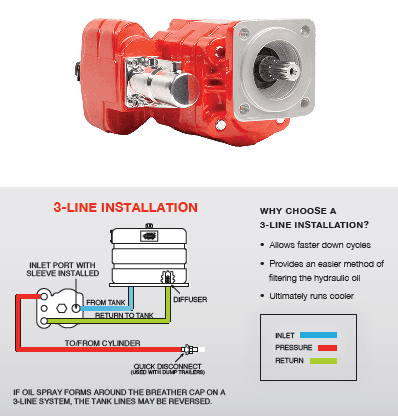
In an open system, the pump is always working, moving oil through the pipes without building up pressure. Both the inlet to the pump and the return valve are hooked up to a hydraulic reservoir. These are also called “open center” systems, because of the open central path of the control valve when it is neutral. In this case, hydraulic fluid returns to the reservoir. The fluid coming from the pump goes to the device and then returns to the reservoir. There may also be a relief valve in the circuit to route any excess fluid to the reservoir. Filters are usually in place to keep the fluid clean.
Open systems tend to be better for low-pressure applications. They also tend to be cheaper and easier to maintain. One caution is that they can create excess heat in the system if the pressure exceeds valve settings. Another location for added heat is in the reservoir, which needs to be big enough to cool the fluid running through it. Open systems can also use multiple pumps to supply power to different systems, such as steering or control.
A closed system connects the return valve directly to the hydraulic pump inlet. It uses a single central pump to move the fluid in a continuous loop. A valve also blocks oil from the pump, instead sending it to an accumulator where it stays pressurized. Oil remains under pressure but doesn’t move unless it is activated. A charge pump supplies cool, filtered oil to the low-pressure side. This step maintains pressure within the loop. A closed system is often used in mobile applications with hydrostatic transmissions and uses one pump to power multiple systems.
These can have smaller reservoirs because they just need to have enough fluid for the charge pump, which is relatively small. An open system can handle more high-pressure applications. The closed system offers a bit more flexibility than an open system, but that also comes with a slightly higher price tag and more complex repair. Closed systems can work with less fluid in smaller hydraulic lines, and the valves can be used to reverse the direction of the flow.
Almost all hydraulic pumps are positive displacement pumps, meaning they deliver a precise amount of fluid. They can be used in high-power applications of over 10,000 psi. Non-positive displacement pumps depend on pressure for the amount of fluid they move, while positive displacement pumps do not. Non-positive pumps are more common in pneumatics and low-pressure applications. They include centrifugal and axial pumps.
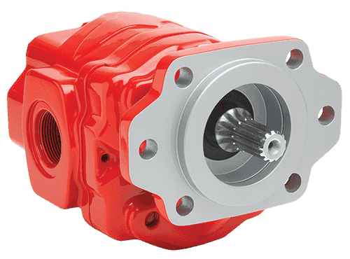
A gearpump is inexpensive and more tolerant of fluid contamination, making them suitable for rough environments. They may be less efficient, however, and wear more quickly.
External gear pumps: These make use of two tight-meshed gears within a housing. One is the driving, or powered, gear, while the other is driven, or free-flowing. The fluid is trapped in the space in between the gears and rotated through the housing. Since it cannot move backward, it is forced through the outlet pump.
Internal gear pump: The internal gear design places an inner gear, possibly with a crescent-shaped spacer, inside of an outer rotor gear. The fluid is moved via eccentricity — the deviation of the gear from circularity — between the gears. The inner gear, with fewer teeth, turns the outer gear, and the spacer goes in between them to create a seal. The fluid is drawn in, moved through the gears, sealed up and discharged.
Unbalanced vane pump: This fixed displacement pump has a driven rotor and vanes that slide out in radial slots. The rotor’s level of eccentricity determines the level of displacement. As it rotates, the space between the vanes increases, creating a vacuum to draw fluid in. The trapped fluid moves around the system via the rotating vanes and is pushed out as the space between them decreases.
Balanced vane pump: The balanced vane pump, also fixed displacement, moves the rotor through an elliptical cam ring. It uses two inlets and outlets on each revolution.
Variable-displacement vane pump: The displacement in this type of pump can change via the eccentricity between the rotor and casing. The outer casing ring is moveable.
In-line axial piston pumps: In-line pumps align the center of the cylinder block with the center of the driveshaft. The angle of the swash/cam plate helps to determine the amount of displacement. The inlet and outlet are located in the valve plate, which connects to each cylinder alternately. As the piston moves up past the inlet port, it pulls in fluid from the reservoir. Similarly, it will push the liquid out of the outlet port as it passes it.
Bent-axis axial piston pumps: The bent-axis pumps line the center of the cylinder block at an angle with the center of the drive shaft. This design works similarly to the in-line axial pump.
Radial piston pumps: A radial piston pump uses seven or nine radial barrels, along with a reaction ring, pintle and driveshaft. The pistons are set radially around the drive shaft, and inlet and outlet ports are in the pintle, a type of hinge.
Now that you know what hydraulics are, you can see that hydraulics have vast applications and can be used in all sorts of different components of the machinery that runs construction, transportation and more. You may even be able to think of some hydraulic system examples of your own now. The power of water has been used for centuries, and now, with the help of valves, pistons and cylinders, hydraulics can run in a variety of different formats. Open and closed, fixed or variable, positive and non-positive — all of these can move massive weights and take advantage of modern engineering. If you run any sort of business, you may be able to put hydraulics to work for you.
At Hard Chrome Specialists, we offer repair services on all types of hydraulic systems as well as plating, electropolishingand custom fabrication. We hope you’ve learned something new today about how hydraulics work and understand a little more about this incredibly powerful system. If you want to learn more about hydraulics, contact us today!


 8613371530291