
piston hydraulic pump how it works manufacturer
Hydraulic piston pumps move fluids throughout professional equipment and industrial machinery. They’re known for their high efficiency and are commonly used in high-pressure applications.
There are also two major types of hydraulic piston pumps: axial and radial; both can have fixed or variable displacement; fixed displacement means that the pump is delivering the same amount of liquid or gas each time, while variable means that the amount of gas or liquid delivered may be different each time. Although both are considered piston pumps, each one operates differently.
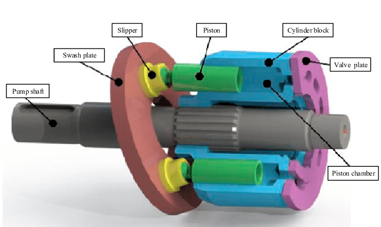
An axial piston pump features four major components: a shaft, swashplate or bent axis, cylinder block, and valve plate. The cylinder block houses the piston pumps, which are laid out cyclically around the drive shaft’s axis (thus why it is named anaxialpiston pump).
The pistons in the cylinder block pump up and down as the drive shaft rotates. The piston’s stroke will vary depending on how it is angled in the swashplate or bent axis. As the pistons move in one direction, they are connected to a suction line, and when they move in the opposite direction, they connect to a discharge channel, allowing a continuous flow of fluid.
The design of a radial piston pump is significantly different from an axial pump. The radial piston pump consists of a cylinder block, rotating camshaft, and pistons. The pistons are arranged around the cylinder block in a radial pattern and diverge from the camshaft like rays. The rotation of the cam causes the pistons to change from suction to discharge and vice versa.
In general, choosing a hydraulic pump requires an application evaluation. You’ll need to know pressure requirements, desired flow rate, speed, horsepower, and the type of fluid the pump will be dispersing.
Radial piston pumps can usually handle all fluids, including mineral oil and water-glycol hydraulic fluid, while axial piston pumps are preferred for extremely high-pressure applications.
Although piston pumps are highly efficient and reliable, contamination, over-pressurization, and inlet blockages can cause the pump to fail. If and when this happens, you’ll need to replace your pump as soon as possible.
When choosing a replacement pump, you’ll have to choose between a direct OEM replacement and a remanufactured pump. Unfortunately, direct OEM replacement pumps and services can be a significant investment. Additionally, if you have outdated equipment, you may not be able to find thepump partsneeded to restore your equipment.
If you’re looking for a quick and relatively inexpensive solution, a remanufactured pump is your best choice. However, if time and money aren’t an issue, a direct OEM replacement will most likely be the best option if the manufacturer hasn’t discontinued the pump.
Do you need help finding the right piston pump? Turn to Panagon Systems. Founded over 25 years ago, we’re an industry-leading remanufacturer of hydraulic piston pumps and motors. We specialize in remanufacturing pumps from brands like Vickers/Eaton, Rexroth, and Caterpillar, and we also carry. All pumps and motors are remanufactured in-house in the United States, guaranteed to meet OEM specifications, and are backed by a one-year warranty.

Piston pumps are durable and relatively simple devices. A basic piston pump is made up of a piston, a chamber, and two valves. The pump operates by driving the piston down into the chamber, thereby compressing the media inside. In a hand pump, this is usually air. Once the pressure of the air exceeds that of the outlet valve spring, the compressed media goes through the open outlet valve. When the piston is drawn back up, it opens the inlet valve and closes the outlet valve, thereby utilizing suction to draw in new media for compression.
Although somewhat expensive, piston pumps are among the most efficient types of pumps. They have an excellent pressure rating (as high as 10,000 psi), but their design makes them susceptible to contaminants. They provide an excellent solution for many high-pressure hydraulic oil pumping applications.
Axial piston pumps are positive displacement pumps that use multiple cylinders grouped around a central axis. The group of cylinders, usually containing an odd number, is called a cylinder block. The pistons within each cylinder are attached to a swashplate. The swashplate is also known as a cam or wobble plate and attaches to a rotating shaft. As the shaft turns, the angle of the swashplate changes, which drives the pistons in and out of their respective cylinders.
Since the swashplate is at an angle to the axis of rotation, the pistons must reciprocate axially as they orbit around the cylinder block axis. The axial motion of the pistons is sinusoidal. As a piston rises, it moves toward the valve plate. At this point in the rotation, the fluid trapped between the buried end of the piston and the valve plate is expelled to the pump"s discharge port through one of the valve plate"s semi-circular ports. As the piston moves back toward the valve plate, the fluid is pushed through the discharge port of the valve plate.
Axial piston pumps can be designed as variable displacement piston pumps, making them very useful for controlling the speeds of hydraulic motors and cylinders. In this design, a swashplate is used to vary the depth to which each piston extends into its cylinder as the pump rotates, affecting the volume of discharge. A pressure compensator piston is used in some designs to maintain a constant discharge pressure under varying loads. Cheaper pressure washers sometimes use fixed-rate designs.
In a typical pressure-compensated pump, the swashplate angle adjusts through the action of a valve using pressure feedback to make sure that the pump output flow is precisely enough to maintain a designated pressure. If the load flow increases, the pressure momentarily decreases, but the pressure-compensation valve senses the decrease and then increases the swashplate angle to increase the pump’s output flow, restoring the desired pressure.
Axial piston pumps can contain most of the necessary circuit controls intrinsically by controlling the swash-plate angle, to regulate flow and pressure. They are very reliable and can allow the rest of the hydraulic system to which they’re attached to be very simple and inexpensive.
They are used to power the hydraulic systems of jet aircrafts, being gear-driven off of the turbine engine"s main shaft, and are often used for automotive air conditioning compressors for cabin cooling. The design of these pumps meets the limited weight and space requirement in the vehicle"s engine bay and reduces vibrations.
Pressure washers also use these pumps, and axial reciprocating motors are used to power many machines. They operate on the same principles as axial piston pumps, except that the circulating fluid is provided under substantial pressure and the piston housing rotates and provides shaft power to another machine. A typical use of an axial reciprocating motor is powering small earthmoving machines such as skid loader machines.
This guide provides a basic understanding of axial piston pumps. To find out more about other types of pumps, read our guide here. For more information on related products, consult our other product guides or visit the Thomas Supplier Discovery Platform to locate potential sources or view details on specific products.

Pumps are mechanical devices used to create fluid flow. There are many different kinds of pumps, from a basic hand pump to vacuum pumps. Many pumps are identified by what they do, for example, boiler feed pumps, pressure washer pumps, and windshield washer pumps, and the intended application is a useful attribute for narrowing down pumps meant for specific applications. This article looks at a particular type of piston pump, the radial piston pump.
Piston pumps are durable and relatively simple devices. A basic piston pump is made up of a piston, a chamber, and two valves. The pump operates by driving the piston down into the chamber, thereby compressing the media inside. In a hydraulic pump, this is some sort of fluid, often water or oil. Once the pressure of the fluid exceeds that of the outlet valve spring, the compressed media goes through the open outlet valve. When the piston is drawn back up, it opens the inlet valve and closes the outlet valve, thereby utilizing suction to draw in new media for compression.
Although somewhat expensive, piston pumps are among the most efficient types of pumps. They have an excellent pressure rating (as high as 10,000 psi), but their design makes them susceptible to contaminants. They provide an excellent solution for many high-pressure hydraulic oil pumping applications. Hydraulic Pumps are any of a class of positive displacement machines used in fluid power applications to provide hydraulic flow to fluid-powered devices such as cylinders, rams, motors, and other devices.
A radial piston pump is a type of hydraulic piston pump. The working pistons extend in a radial direction symmetrically around the shaft, marking the main difference beween them and another piston pump, the axial piston pump, which has axially rotating pistons.
Radial piston pumps arrange a series of pistons radially in a cylindrical block around a rotor hub. The block consists of a pintle, a cylinder barrel with pistons, and a rotor. The pintle directs the fluid in and out of the cylinder. The rotor, mounted eccentrically in the pump housing, forces the pistons in and out of cylinders as it rotates, which cause hydraulic fluid to be sucked into the cylinder cavity and then be discharged from it. Inlets and outlets for the pump are located in a valve in a central hub. Each piston is connected to inlet port when it starts extending while it is connected to the outlet port when start retracting.
An alternative design places inlets and outlets around the perimeter of the pump housing. Radial piston pumps can be purchased as fixed- or variable-displacement models. In the variable-displacement version, the eccentricity of the rotor in the pump housing is altered to decrease or increase the stroke of the pistons.
They have many advantages, such as high efficiency, high-pressure capability up to 1,000 bar or 14000 psi, low flow and pressure ripple, low noise level, very high load at the lowest speed, and high reliability. A disadvantage is that they are bigger than axial pumps, because of the bigger radial dimensions, and so cannot always be used in applications with space constraints.
The hydrostatically balanced parts of radial piston pumps make it possible to use them with various hydraulic fluids such as mineral oil, biodegradable oil, HFC (water-glycol), HFD (synthetic ester), HFA (oil in water), and cutting emulsion. Radial pumps are used for machine tools, such as the displacement of cutting emulsion, and as a supply for hydraulic equipment like cylinders. They are also used in high-pressure units (HPU) for overload protection, and for test rigs.
The automotive sector uses them for automatic transmission and hydraulic suspension control in upper-class cars. Radial piston pumps are also used in plastic- and powder injection molding and wind energy.
This guide provides a basic understanding of radial piston pumps. To find out more about other types of pumps, read our guide here. For more information on related products, consult our other product guides or visit the Thomas Supplier Discovery Platform to locate potential sources or view details on specific products.

This website is using a security service to protect itself from online attacks. The action you just performed triggered the security solution. There are several actions that could trigger this block including submitting a certain word or phrase, a SQL command or malformed data.

This website is using a security service to protect itself from online attacks. The action you just performed triggered the security solution. There are several actions that could trigger this block including submitting a certain word or phrase, a SQL command or malformed data.

A hydraulic pump is a mechanical device that converts mechanical power into hydraulic energy. It generates flow with enough power to overcome pressure induced by the load.
A hydraulic pump performs two functions when it operates. Firstly, its mechanical action creates a vacuum at the pump inlet, subsequently allowing atmospheric pressure to force liquid from the reservoir and then pumping it through to the inlet line of the pump. Secondly, its mechanical action delivers this liquid to the pump outlet and forces it into the hydraulic system.
The three most common hydraulic pump designs are: vane pump, gear pump and radial piston pump. All are well suited to common hydraulic uses, however the piston design is recommended for higher pressures.
Most pumps used in hydraulic systems are positive-displacement pumps. This means that they displace (deliver) the same amount of liquid for each rotating cycle of the pumping element. The delivery per cycle remains almost constant, regardless of changes in pressure.
Positive-displacement pumps are grouped into fixed or variable displacement. A fixed displacement pump’s output remains constant during each pumping cycle and at a given pump speed. Altering the geometry of the displacement chamber changes the variable displacement pump’s output.
Fixed displacement pumps (or screw pumps) make little noise, so they are perfect for use in for example theatres and opera houses. Variable displacement pumps, on the other hand, are particularly well suited in circuits using hydraulic motors and where variable speeds or the ability to reverse is needed.
Applications commonly using a piston pump include: marine auxiliary power, machine tools, mobile and construction equipment, metal forming and oil field equipment.
As the name suggests, a piston pump operates through pistons that move back and forth in the cylinders connected to the hydraulic pump. A piston pump also has excellent sealing capabilities.
A hydraulic piston pump can operate at large volumetric levels thanks to low oil leakage. Some plungers require valves at the suction and pressure ports, whilst others require them with the input and output channels. Valves (and their sealing properties) at the end of the piston pumps will further enhance the performance at higher pressures.
The axial piston pump is possibly the most widely used variable displacement pump. It’s used in everything from heavy industrial to mobile applications. Different compensation techniques will continuously alter the pump’s fluid discharge per revolution. And moreover, also alter the system pressure based on load requirements, maximum pressure cut-off settings and ratio control. This implies significant power savings.
Two principles characterise the axial piston pump. Firstly the swash plate or bent axis design and secondly the system parameters. System parameters include the decision on whether or not the pump is used in an open or closed circuit.
The return line in a closed loop circuit is under constant pressure. This must be considered when designing an axial piston pump that is used in a closed loop circuit. It is also very important that a variable displacement volume pump is installed and operates alongside the axial piston pump in the systems. Axial piston pumps can interchange between a pump and a motor in some fixed displacement configurations.
The swivel angle determines the displacement volume of the bent axis pump. The pistons in the cylinder bore moves when the shaft rotates. The swash plate, in the swash plate design, sustain the turning pistons. Moreover, the angle of the swash plate decides the piston stroke.
The bent axis principle, fixed or adjustable displacement, exist in two different designs. The first design is the Thoma-principle with maximum 25 degrees angle, designed by the German engineer Hans Thoma and patented in 1935. The second design goes under the name Wahlmark-principle, named after Gunnar Axel Wahlmark (patent 1960). The latter features spherical-shaped pistons in one piece with the piston rod and piston rings. And moreover a maximum 40 degrees between the driveshaft centre-line and pistons.
In general, the largest displacements are approximately one litre per revolution. However if necessary, a two-litre swept volume pump can be built. Often variable-displacement pumps are used, so that the oil flow can be adjusted carefully. These pumps generally operate with a working pressure of up to 350–420 bars in continuous work
Radial piston pumps are used especially for high pressure and relatively small flows. Pressures of up to 650 bar are normal. The plungers are connected to a floating ring. A control lever moves the floating ring horizontally by a control lever and thus causes an eccentricity in the centre of rotation of the plungers. The amount of eccentricity is controlled to vary the discharge. Moreover, shifting the eccentricity to the opposite side seamlessly reverses the suction and discharge.
Radial piston pumps are the only pumps that work continuously under high pressure for long periods of time. Examples of applications include: presses, machines for processing plastic and machine tools.
A vane pump uses the back and forth movement of rectangle-shaped vanes inside slots to move fluids. They are sometimes also referred to as sliding vane pumps.
The simplest vane pump consists of a circular rotor, rotating inside of a larger circular cavity. The centres of the two circles are offset, causing eccentricity. Vanes slide into and out of the rotor and seal on all edges. This creates vane chambers that do the pumping work.
A vacuum is generated when the vanes travel further than the suction port of the pump. This is how the oil is drawn into the pumping chamber. The oil travels through the ports and is then forced out of the discharge port of the pump. Direction of the oil flow may alter, dependent on the rotation of the pump. This is the case for many rotary pumps.
Vane pumps operate most efficiently with low viscosity oils, such as water and petrol. Higher viscosity fluids on the other hand, may cause issues for the vane’s rotation, preventing them from moving easily in the slots.
Gear pumps are one of the most common types of pumps for hydraulic fluid power applications. Here at Hydraulics Online, we offer a wide range of high-powered hydraulic gear pumps suitable for industrial, commercial and domestic use. We provide a reliable pump model, whatever the specifications of your hydraulic system. And we furthermore ensure that it operates as efficiently as possible.
Johannes Kepler invented the gear pump around year 1600. Fluid carried between the teeth of two meshing gears produces the flow. The pump housing and side plates, also called wear or pressure plates, enclose the chambers, which are formed between adjacent gear teeth. The pump suction creates a partial vacuum. Thereafter fluid flows in to fill the space and is carried around the discharge of the gears. Next the fluid is forced out as the teeth mesh (at the discharge end).
Some gear pumps are quite noisy. However, modern designs incorporating split gears, helical gear teeth and higher precision/quality tooth profiles are much quieter. On top of this, they can mesh and un-mesh more smoothly. Subsequently this reduces pressure ripples and related detrimental problems.
Catastrophic breakdowns are easier to prevent with hydraulic gear pumps. This is because the gears gradually wear down the housing and/or main bushings. Therefore reducing the volumetric efficiency of the pump gradually until it is all but useless. This often happens long before wear causes the unit to seize or break down.
Can hydraulic gear pumps be reversed? Yes, most pumps can be reversed by taking the pump apart and flipping the center section. This is why most gear pumps are symmetrical.
External gear pumps use two external spur gears. Internal gear pumps use an external and an internal spur gear. Moreover, the spur gear teeth face inwards for internal gear pumps. Gear pumps are positive displacement (or fixed displacement). In other words, they pump a constant amount of fluid for each revolution. Some gear pumps are interchangeable and function both as a motor and a pump.
The petrochemical industry uses gear pumps to move: diesel oil, pitch, lube oil, crude oil and other fluids. The chemical industry also uses them for materials such as: plastics, acids, sodium silicate, mixed chemicals and other media. Finally, these pumps are also used to transport: ink, paint, resins and adhesives and in the food industry.
Mathematical calculations are key to any type of hydraulic motor or pump design, but are especially interesting in the gerotor design. The inner rotor has N teeth, where N > 2. The outer rotor must have N + 1 teeth (= one more tooth than the inner rotor) in order for the design to work.

www.powermotiontech.com is using a security service for protection against online attacks. An action has triggered the service and blocked your request.
Please try again in a few minutes. If the issue persist, please contact the site owner for further assistance. Reference ID IP Address Date and Time 8bf2006c85a66667641f5dd58dcb3d35 63.210.148.230 03/12/2023 08:51 PM UTC
Hydraulic pumps are mechanisms in hydraulic systems that move hydraulic fluid from point to point initiating the production of hydraulic power. Hydraulic pumps are sometimes incorrectly referred to as “hydrolic” pumps.
They are an important device overall in the hydraulics field, a special kind of power transmission which controls the energy which moving fluids transmit while under pressure and change into mechanical energy. Other kinds of pumps utilized to transmit hydraulic fluids could also be referred to as hydraulic pumps. There is a wide range of contexts in which hydraulic systems are applied, hence they are very important in many commercial, industrial, and consumer utilities.
“Power transmission” alludes to the complete procedure of technologically changing energy into a beneficial form for practical applications. Mechanical power, electrical power, and fluid power are the three major branches that make up the power transmission field. Fluid power covers the usage of moving gas and moving fluids for the transmission of power. Hydraulics are then considered as a sub category of fluid power that focuses on fluid use in opposition to gas use. The other fluid power field is known as pneumatics and it’s focused on the storage and release of energy with compressed gas.
"Pascal"s Law" applies to confined liquids. Thus, in order for liquids to act hydraulically, they must be contained within a system. A hydraulic power pack or hydraulic power unit is a confined mechanical system that utilizes liquid hydraulically. Despite the fact that specific operating systems vary, all hydraulic power units share the same basic components. A reservoir, valves, a piping/tubing system, a pump, and actuators are examples of these components. Similarly, despite their versatility and adaptability, these mechanisms work together in related operating processes at the heart of all hydraulic power packs.
The hydraulic reservoir"s function is to hold a volume of liquid, transfer heat from the system, permit solid pollutants to settle, and aid in releasing moisture and air from the liquid.
Mechanical energy is changed to hydraulic energy by the hydraulic pump. This is accomplished through the movement of liquid, which serves as the transmission medium. All hydraulic pumps operate on the same basic principle of dispensing fluid volume against a resistive load or pressure.
Hydraulic valves are utilized to start, stop, and direct liquid flow in a system. Hydraulic valves are made of spools or poppets and can be actuated hydraulically, pneumatically, manually, electrically, or mechanically.
The end result of Pascal"s law is hydraulic actuators. This is the point at which hydraulic energy is transformed back to mechanical energy. This can be accomplished by using a hydraulic cylinder to transform hydraulic energy into linear movement and work or a hydraulic motor to transform hydraulic energy into rotational motion and work. Hydraulic motors and hydraulic cylinders, like hydraulic pumps, have various subtypes, each meant for specific design use.
The essence of hydraulics can be found in a fundamental physical fact: fluids are incompressible. (As a result, fluids more closely resemble solids than compressible gasses) The incompressible essence of fluid allows it to transfer force and speed very efficiently. This fact is summed up by a variant of "Pascal"s Principle," which states that virtually all pressure enforced on any part of a fluid is transferred to every other part of the fluid. This scientific principle states, in other words, that pressure applied to a fluid transmits equally in all directions.
Furthermore, the force transferred through a fluid has the ability to multiply as it moves. In a slightly more abstract sense, because fluids are incompressible, pressurized fluids should keep a consistent pressure just as they move. Pressure is defined mathematically as a force acting per particular area unit (P = F/A). A simplified version of this equation shows that force is the product of area and pressure (F = P x A). Thus, by varying the size or area of various parts inside a hydraulic system, the force acting inside the pump can be adjusted accordingly (to either greater or lesser). The need for pressure to remain constant is what causes force and area to mirror each other (on the basis of either shrinking or growing). A hydraulic system with a piston five times larger than a second piston can demonstrate this force-area relationship. When a force (e.g., 50lbs) is exerted on the smaller piston, it is multiplied by five (e.g., 250 lbs) and transmitted to the larger piston via the hydraulic system.
Hydraulics is built on fluids’ chemical properties and the physical relationship between pressure, area, and force. Overall, hydraulic applications allow human operators to generate and exert immense mechanical force with little to no physical effort. Within hydraulic systems, both oil and water are used to transmit power. The use of oil, on the other hand, is far more common, owing in part to its extremely incompressible nature.
Pressure relief valves prevent excess pressure by regulating the actuators’ output and redirecting liquid back to the reservoir when necessary. Directional control valves are used to change the size and direction of hydraulic fluid flow.
While hydraulic power transmission is remarkably useful in a wide range of professional applications, relying solely on one type of power transmission is generally unwise. On the contrary, the most efficient strategy is to combine a wide range of power transmissions (pneumatic, hydraulic, mechanical, and electrical). As a result, hydraulic systems must be carefully embedded into an overall power transmission strategy for the specific commercial application. It is necessary to invest in locating trustworthy and skilled hydraulic manufacturers/suppliers who can aid in the development and implementation of an overall hydraulic strategy.
The intended use of a hydraulic pump must be considered when selecting a specific type. This is significant because some pumps may only perform one function, whereas others allow for greater flexibility.
The pump"s material composition must also be considered in the application context. The cylinders, pistons, and gears are frequently made of long-lasting materials like aluminum, stainless steel, or steel that can withstand the continuous wear of repeated pumping. The materials must be able to withstand not only the process but also the hydraulic fluids. Composite fluids frequently contain oils, polyalkylene glycols, esters, butanol, and corrosion inhibitors (though water is used in some instances). The operating temperature, flash point, and viscosity of these fluids differ.
In addition to material, manufacturers must compare hydraulic pump operating specifications to make sure that intended utilization does not exceed pump abilities. The many variables in hydraulic pump functionality include maximum operating pressure, continuous operating pressure, horsepower, operating speed, power source, pump weight, and maximum fluid flow. Standard measurements like length, rod extension, and diameter should be compared as well. Because hydraulic pumps are used in lifts, cranes, motors, and other heavy machinery, they must meet strict operating specifications.
It is critical to recall that the overall power generated by any hydraulic drive system is influenced by various inefficiencies that must be considered in order to get the most out of the system. The presence of air bubbles within a hydraulic drive, for example, is known for changing the direction of the energy flow inside the system (since energy is wasted on the way to the actuators on bubble compression). Using a hydraulic drive system requires identifying shortfalls and selecting the best parts to mitigate their effects. A hydraulic pump is the "generator" side of a hydraulic system that initiates the hydraulic procedure (as opposed to the "actuator" side that completes the hydraulic procedure). Regardless of disparities, all hydraulic pumps are responsible for displacing liquid volume and transporting it to the actuator(s) from the reservoir via the tubing system. Some form of internal combustion system typically powers pumps.
While the operation of hydraulic pumps is normally the same, these mechanisms can be split into basic categories. There are two types of hydraulic pumps to consider: gear pumps and piston pumps. Radial and axial piston pumps are types of piston pumps. Axial pumps produce linear motion, whereas radial pumps can produce rotary motion. The gear pump category is further subdivided into external gear pumps and internal gear pumps.
Each type of hydraulic pump, regardless of piston or gear, is either double-action or single-action. Single-action pumps can only pull, push, or lift in one direction, while double-action pumps can pull, push, or lift in multiple directions.
Vane pumps are positive displacement pumps that maintain a constant flow rate under varying pressures. It is a pump that self-primes. It is referred to as a "vane pump" because the effect of the vane pressurizes the liquid.
This pump has a variable number of vanes mounted onto a rotor that rotates within the cavity. These vanes may be variable in length and tensioned to maintain contact with the wall while the pump draws power. The pump also features a pressure relief valve, which prevents pressure rise inside the pump from damaging it.
Internal gear pumps and external gear pumps are the two main types of hydraulic gear pumps. Pumps with external gears have two spur gears, the spurs of which are all externally arranged. Internal gear pumps also feature two spur gears, and the spurs of both gears are internally arranged, with one gear spinning around inside the other.
Both types of gear pumps deliver a consistent amount of liquid with each spinning of the gears. Hydraulic gear pumps are popular due to their versatility, effectiveness, and fairly simple design. Furthermore, because they are obtainable in a variety of configurations, they can be used in a wide range of consumer, industrial, and commercial product contexts.
Hydraulic ram pumps are cyclic machines that use water power, also referred to as hydropower, to transport water to a higher level than its original source. This hydraulic pump type is powered solely by the momentum of moving or falling water.
Ram pumps are a common type of hydraulic pump, especially among other types of hydraulic water pumps. Hydraulic ram pumps are utilized to move the water in the waste management, agricultural, sewage, plumbing, manufacturing, and engineering industries, though only about ten percent of the water utilized to run the pump gets to the planned end point.
Despite this disadvantage, using hydropower instead of an external energy source to power this kind of pump makes it a prominent choice in developing countries where the availability of the fuel and electricity required to energize motorized pumps is limited. The use of hydropower also reduces energy consumption for industrial factories and plants significantly. Having only two moving parts is another advantage of the hydraulic ram, making installation fairly simple in areas with free falling or flowing water. The water amount and the rate at which it falls have an important effect on the pump"s success. It is critical to keep this in mind when choosing a location for a pump and a water source. Length, size, diameter, minimum and maximum flow rates, and speed of operation are all important factors to consider.
Hydraulic water pumps are machines that move water from one location to another. Because water pumps are used in so many different applications, there are numerous hydraulic water pump variations.
Water pumps are useful in a variety of situations. Hydraulic pumps can be used to direct water where it is needed in industry, where water is often an ingredient in an industrial process or product. Water pumps are essential in supplying water to people in homes, particularly in rural residences that are not linked to a large sewage circuit. Water pumps are required in commercial settings to transport water to the upper floors of high rise buildings. Hydraulic water pumps in all of these situations could be powered by fuel, electricity, or even by hand, as is the situation with hydraulic hand pumps.
Water pumps in developed economies are typically automated and powered by electricity. Alternative pumping tools are frequently used in developing economies where dependable and cost effective sources of electricity and fuel are scarce. Hydraulic ram pumps, for example, can deliver water to remote locations without the use of electricity or fuel. These pumps rely solely on a moving stream of water’s force and a properly configured number of valves, tubes, and compression chambers.
Electric hydraulic pumps are hydraulic liquid transmission machines that use electricity to operate. They are frequently used to transfer hydraulic liquid from a reservoir to an actuator, like a hydraulic cylinder. These actuation mechanisms are an essential component of a wide range of hydraulic machinery.
There are several different types of hydraulic pumps, but the defining feature of each type is the use of pressurized fluids to accomplish a job. The natural characteristics of water, for example, are harnessed in the particular instance of hydraulic water pumps to transport water from one location to another. Hydraulic gear pumps and hydraulic piston pumps work in the same way to help actuate the motion of a piston in a mechanical system.
Despite the fact that there are numerous varieties of each of these pump mechanisms, all of them are powered by electricity. In such instances, an electric current flows through the motor, which turns impellers or other devices inside the pump system to create pressure differences; these differential pressure levels enable fluids to flow through the pump. Pump systems of this type can be utilized to direct hydraulic liquid to industrial machines such as commercial equipment like elevators or excavators.
Hydraulic hand pumps are fluid transmission machines that utilize the mechanical force generated by a manually operated actuator. A manually operated actuator could be a lever, a toggle, a handle, or any of a variety of other parts. Hydraulic hand pumps are utilized for hydraulic fluid distribution, water pumping, and various other applications.
Hydraulic hand pumps may be utilized for a variety of tasks, including hydraulic liquid direction to circuits in helicopters and other aircraft, instrument calibration, and piston actuation in hydraulic cylinders. Hydraulic hand pumps of this type use manual power to put hydraulic fluids under pressure. They can be utilized to test the pressure in a variety of devices such as hoses, pipes, valves, sprinklers, and heat exchangers systems. Hand pumps are extraordinarily simple to use.
Each hydraulic hand pump has a lever or other actuation handle linked to the pump that, when pulled and pushed, causes the hydraulic liquid in the pump"s system to be depressurized or pressurized. This action, in the instance of a hydraulic machine, provides power to the devices to which the pump is attached. The actuation of a water pump causes the liquid to be pulled from its source and transferred to another location. Hydraulic hand pumps will remain relevant as long as hydraulics are used in the commerce industry, owing to their simplicity and easy usage.
12V hydraulic pumps are hydraulic power devices that operate on 12 volts DC supplied by a battery or motor. These are specially designed processes that, like all hydraulic pumps, are applied in commercial, industrial, and consumer places to convert kinetic energy into beneficial mechanical energy through pressurized viscous liquids. This converted energy is put to use in a variety of industries.
Hydraulic pumps are commonly used to pull, push, and lift heavy loads in motorized and vehicle machines. Hydraulic water pumps may also be powered by 12V batteries and are used to move water out of or into the desired location. These electric hydraulic pumps are common since they run on small batteries, allowing for ease of portability. Such portability is sometimes required in waste removal systems and vehiclies. In addition to portable and compact models, options include variable amp hour productions, rechargeable battery pumps, and variable weights.
While non rechargeable alkaline 12V hydraulic pumps are used, rechargeable ones are much more common because they enable a continuous flow. More considerations include minimum discharge flow, maximum discharge pressure, discharge size, and inlet size. As 12V batteries are able to pump up to 150 feet from the ground, it is imperative to choose the right pump for a given use.
Air hydraulic pumps are hydraulic power devices that use compressed air to stimulate a pump mechanism, generating useful energy from a pressurized liquid. These devices are also known as pneumatic hydraulic pumps and are applied in a variety of industries to assist in the lifting of heavy loads and transportation of materials with minimal initial force.
Air pumps, like all hydraulic pumps, begin with the same components. The hydraulic liquids, which are typically oil or water-based composites, require the use of a reservoir. The fluid is moved from the storage tank to the hydraulic cylinder via hoses or tubes connected to this reservoir. The hydraulic cylinder houses a piston system and two valves. A hydraulic fluid intake valve allows hydraulic liquid to enter and then traps it by closing. The discharge valve is the point at which the high pressure fluid stream is released. Air hydraulic pumps have a linked air cylinder in addition to the hydraulic cylinder enclosing one end of the piston.
The protruding end of the piston is acted upon by a compressed air compressor or air in the cylinder. When the air cylinder is empty, a spring system in the hydraulic cylinder pushes the piston out. This makes a vacuum, which sucks fluid from the reservoir into the hydraulic cylinder. When the air compressor is under pressure, it engages the piston and pushes it deeper into the hydraulic cylinder and compresses the liquids. This pumping action is repeated until the hydraulic cylinder pressure is high enough to forcibly push fluid out through the discharge check valve. In some instances, this is connected to a nozzle and hoses, with the important part being the pressurized stream. Other uses apply the energy of this stream to pull, lift, and push heavy loads.
Hydraulic piston pumps transfer hydraulic liquids through a cylinder using plunger-like equipment to successfully raise the pressure for a machine, enabling it to pull, lift, and push heavy loads. This type of hydraulic pump is the power source for heavy-duty machines like excavators, backhoes, loaders, diggers, and cranes. Piston pumps are used in a variety of industries, including automotive, aeronautics, power generation, military, marine, and manufacturing, to mention a few.
Hydraulic piston pumps are common due to their capability to enhance energy usage productivity. A hydraulic hand pump energized by a hand or foot pedal can convert a force of 4.5 pounds into a load-moving force of 100 pounds. Electric hydraulic pumps can attain pressure reaching 4,000 PSI. Because capacities vary so much, the desired usage pump must be carefully considered. Several other factors must also be considered. Standard and custom configurations of operating speeds, task-specific power sources, pump weights, and maximum fluid flows are widely available. Measurements such as rod extension length, diameter, width, and height should also be considered, particularly when a hydraulic piston pump is to be installed in place of a current hydraulic piston pump.
Hydraulic clutch pumps are mechanisms that include a clutch assembly and a pump that enables the user to apply the necessary pressure to disengage or engage the clutch mechanism. Hydraulic clutches are crafted to either link two shafts and lock them together to rotate at the same speed or detach the shafts and allow them to rotate at different speeds as needed to decelerate or shift gears.
Hydraulic pumps change hydraulic energy to mechanical energy. Hydraulic pumps are particularly designed machines utilized in commercial, industrial, and residential areas to generate useful energy from different viscous liquids pressurization. Hydraulic pumps are exceptionally simple yet effective machines for moving fluids. "Hydraulic" is actually often misspelled as "Hydralic". Hydraulic pumps depend on the energy provided by hydraulic cylinders to power different machines and mechanisms.
There are several different types of hydraulic pumps, and all hydraulic pumps can be split into two primary categories. The first category includes hydraulic pumps that function without the assistance of auxiliary power sources such as electric motors and gas. These hydraulic pump types can use the kinetic energy of a fluid to transfer it from one location to another. These pumps are commonly called ram pumps. Hydraulic hand pumps are never regarded as ram pumps, despite the fact that their operating principles are similar.
The construction, excavation, automotive manufacturing, agriculture, manufacturing, and defense contracting industries are just a few examples of operations that apply hydraulics power in normal, daily procedures. Since hydraulics usage is so prevalent, hydraulic pumps are unsurprisingly used in a wide range of machines and industries. Pumps serve the same basic function in all contexts where hydraulic machinery is used: they transport hydraulic fluid from one location to another in order to generate hydraulic energy and pressure (together with the actuators).
Elevators, automotive brakes, automotive lifts, cranes, airplane flaps, shock absorbers, log splitters, motorboat steering systems, garage jacks and other products use hydraulic pumps. The most common application of hydraulic pumps in construction sites is in big hydraulic machines and different types of "off-highway" equipment such as excavators, dumpers, diggers, and so on. Hydraulic systems are used in other settings, such as offshore work areas and factories, to power heavy machinery, cut and bend material, move heavy equipment, and so on.
Fluid’s incompressible nature in hydraulic systems allows an operator to make and apply mechanical power in an effective and efficient way. Practically all force created in a hydraulic system is applied to the intended target.
Because of the relationship between area, pressure, and force (F = P x A), modifying the force of a hydraulic system is as simple as changing the size of its components.
Hydraulic systems can transfer energy on an equal level with many mechanical and electrical systems while being significantly simpler in general. A hydraulic system, for example, can easily generate linear motion. On the contrary, most electrical and mechanical power systems need an intermediate mechanical step to convert rotational motion to linear motion.
Hydraulic systems are typically smaller than their mechanical and electrical counterparts while producing equivalents amounts of power, providing the benefit of saving physical space.
Hydraulic systems can be used in a wide range of physical settings due to their basic design (a pump attached to actuators via some kind of piping system). Hydraulic systems could also be utilized in environments where electrical systems would be impractical (for example underwater).
By removing electrical safety hazards, using hydraulic systems instead of electrical power transmission improves relative safety (for example explosions, electric shock).
The amount of power that hydraulic pumps can generate is a significant, distinct advantage. In certain cases, a hydraulic pump could generate ten times the power of an electrical counterpart. Some hydraulic pumps (for example, piston pumps) cost more than the ordinary hydraulic component. These drawbacks, however, can be mitigated by the pump"s power and efficiency. Despite their relatively high cost, piston pumps are treasured for their strength and capability to transmit very viscous fluids.
Handling hydraulic liquids is messy, and repairing leaks in a hydraulic pump can be difficult. Hydraulic liquid that leaks in hot areas may catch fire. Hydraulic lines that burst may cause serious injuries. Hydraulic liquids are corrosive as well, though some are less so than others. Hydraulic systems need frequent and intense maintenance. Parts with a high factor of precision are frequently required in systems. If the power is very high and the pipeline cannot handle the power transferred by the liquid, the high pressure received by the liquid may also cause work accidents.
Even though hydraulic systems are less complex than electrical or mechanical systems, they are still complex systems that should be handled with caution. Avoiding physical contact with hydraulic systems is an essential safety precaution when engaging with them. Even when a hydraulic machine is not in use, active liquid pressure within the system can be a hazard.
Inadequate pumps can cause mechanical failure in the place of work that can have serious and costly consequences. Although pump failure has historically been unpredictable, new diagnostic technology continues to improve on detecting methods that previously relied solely on vibration signals. Measuring discharge pressures enables manufacturers to forecast pump wear more accurately. Discharge sensors are simple to integrate into existing systems, increasing the hydraulic pump"s safety and versatility.
Hydraulic pumps are devices in hydraulic systems that move hydraulic fluid from point to point, initiating hydraulic power production. They are an important device overall in the hydraulics field, a special kind of power transmission that controls the energy which moving fluids transmit while under pressure and change into mechanical energy. Hydraulic pumps are divided into two categories namely gear pumps and piston pumps. Radial and axial piston pumps are types of piston pumps. Axial pumps produce linear motion, whereas radial pumps can produce rotary motion. The construction, excavation, automotive manufacturing, agriculture, manufacturing, and defense contracting industries are just a few examples of operations that apply hydraulics power in normal, daily procedures.

The popularity of hydraulic piston pumps stems from their ability to maximize energy use and productivity. Even a hydraulic hand pump, which is powered by a foot or hand pedal, can convert as little as 4.5 pounds of force into 100 pounds of load-moving force. Electric hydraulic pumps can reach pressure ranges up to 4,000 PSI. As capacities show such variability, the intended use of a pump should be carefully considered. Several other variables should also be taken into account.
Task-specific power sources, operating speeds, maximum fluid flows and pump weights are widely available in standard and custom configurations. Measurements such as diameter, rod extension length, height and width should also be considered, especially when a hydraulic piston pump is to be fitted to a pre-existing hydraulic system.There are two basic variations of hydraulic piston pumps: axial and radial pistons. The essential difference between the two is the placement of the pistons within the hydraulic cylinder and the directionality of the movement. Axial pistons run parallel to the cylinder, while radial pistons are perpendicular to an inner column running through the cylinder. The latter provides a rotary movement. Axial pistons provide linear motion and are more popular in heavy machinery contexts.
Both can be single action or double action pumps. Despite the differing piston placements, both systems function in a similar fashion. Hydraulic fluids, usually oil or water composites, are housed in a reservoir connected to the main cylinder by tubes or hoses. The cylinder houses the pistons as well as one or more intake check valve and an equal number of discharge check valves. When the piston is withdrawn it creates a vacuum, and the liquid solution is pulled into the cylinder.
The piston is then returned to its original position and the intake valve is sealed. This creates pressure within the enclosed space and compresses the fluids. The plunger-like action is repeated until enough pressure is accumulated to force the hydraulic fluids out through the discharge valve. This creates the energy needed to work the attached machinery and move the intended load.

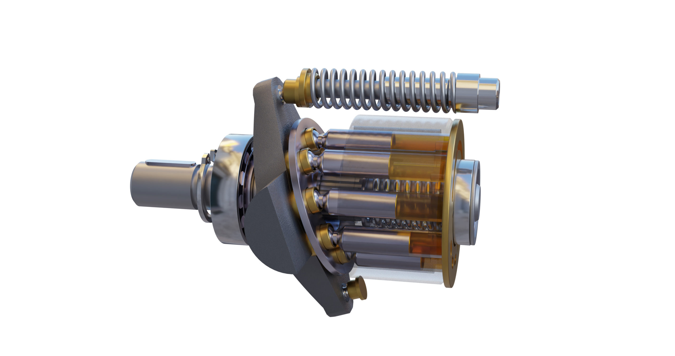
An axial piston pump is a positive displacement pump that has a number of pistons in a circular array within a hydraulic motor or an automotive air conditioning compressor.
An axial piston pump has a number of pistons (usually an odd number) arranged in a circular array within a housing which is commonly referred to as a cylinder block, barrel. This cylinder block is driven to rotate about its axis of symmetry by an integral shaft that is, more or less, aligned with the pumping pistons (usually parallel but not necessarily).
Mating surfaces. One end of the cylinder block is convex and wears against a mating surface on a stationary valve plate. The inlet and outlet fluid of the pump pass through different parts of the sliding interface between the cylinder block and valve plate. The valve plate has two semi-circular ports that allow inlet of the operating fluid and exhaust of the outlet fluid respectively.
Protruding pistons. The pumping pistons protrude from the opposite end of the cylinder block. There are numerous configurations used for the exposed ends of the pistons but in all cases they bear against a cam. In variable displacement units, the cam is movable and commonly referred to as a yoke or hanger. For conceptual purposes, the cam can be represented by a plane, the orientation of which, in combination with shaft rotation, provides the cam action that leads to piston reciprocation and thus pumping. The angle between a vector normal to the cam plane and the cylinder block axis of rotation, called the cam angle, is one variable that determines the displacement of the pump or the amount of fluid pumped per shaft revolution. Variable displacement units have the ability to vary the cam angle during operation whereas fixed displacement units do not.
Reciprocating pistons. As the cylinder block rotates, the exposed ends of the pistons are constrained to follow the surface of the cam plane. Since the cam plane is at an angle to the axis of rotation, the pistons must reciprocate axially as they precess about the cylinder block axis. The axial motion of the pistons is sinusoidal. During the rising portion of the piston"s reciprocation cycle, the piston moves toward the valve plate. Also, during this time, the fluid trapped between the buried end of the piston and the valve plate is vented to the pump"s discharge port through one of the valve plate"s semi-circular ports - the discharge port. As the piston moves toward the valve plate, fluid is pushed or displaced through the discharge port of the valve plate.
Effect of precession. When the piston is at the top of the reciprocation cycle (commonly referred to as top-dead-center or just TDC), the connection between the trapped fluid chamber and the pump"s discharge port is closed. Shortly thereafter, that same chamber becomes open to the pump"s inlet port. As the piston continues to precess about the cylinder block axis, it moves away from the valve plate thereby increasing the volume of the trapped chamber. As this occurs, fluid enters the chamber from the pump"s inlet to fill the void. This process continues until the piston reaches the bottom of the reciprocation cylinder - commonly referred to as bottom-dead-center or BDC. At BDC, the connection between the pumping chamber and inlet port is closed. Shortly thereafter, the chamber becomes open to the discharge port again and the pumping cycle starts over.
Variable displacement. In a variable displacement pump, if the vector normal to the cam plane (swash plate) is set parallel to the axis of rotation, there is no movement of the pistons in their cylinders. Thus there is no output. Movement of the swash plate controls pump output from zero to maximum. There are two kinds of variable-displacement axial piston pumps:
direct displacement control pump, a kind of axial piston pump with a direct displacement control. A direct displacement control uses a mechanical lever attached to the swashplate of the axial piston pump. Higher system pressures require more force to move that lever, making direct displacement control only suitable for light or medium duty pumps. Heavy duty pumps require servo control.linkages and springs and in some cases magnets rather than a shaft to a motor located outside of the pump (thereby reducing the number of moving parts), keeping parts protected and lubricated and reducing the resistance against the flow of liquid.
Pressure. In a typical pressure-compensated pump, the swash plate angle is adjusted through the action of a valve which uses pressure feedback so that the instantaneous pump output flow is exactly enough to maintain a designated pressure. If the load flow increases, pressure will momentarily decrease but the pressure-compensation valve will sense the decrease and then increase the swash plate angle to increase pump output flow so that the desired pressure is restored. In reality most systems use pressure as a control for this type of pump. The operating pressure reaches, say, 200 bar (20 MPa or 2900 psi) and the swash plate is driven towards zero angle (piston stroke nearly zero) and with the inherent leaks in the system allows the pump to stabilise at the delivery volume that maintains the set pressure. As demand increases the swash plate is moved to a greater angle, piston stroke increases and the volume of fluid increases; if the demand slackens the pressure will rise, and the pumped volume diminishes as the pressure rises. At maximum system pressure the output is once again almost zero. If the fluid demand increases beyond the capacity of the pump to deliver, the system pressure will drop to near zero. The swash plate angle will remain at the maximum allowed, and the pistons will operate at full stroke. This continues until system flow-demand eases and the pump"s capacity is greater than demand. As the pressure rises the swash-plate angle modulates to try to not exceed the maximum pressure while meeting the flow demand.
Designers have a number of problems to overcome in designing axial piston pumps. One is managing to be able to manufacture a pump with the fine tolerances necessary for efficient operation. The mating faces between the rotary piston-cylinder assembly and the stationary pump body have to be almost a perfect seal while the rotary part turns at perhaps 3000 rpm. The pistons are usually less than half an inch (13 mm) in diameter with similar stroke lengths. Keeping the wall to piston seal tight means that very small clearances are involved and that materials have to be closely matched for similar coefficient of expansion.
The pistons have to be drawn outwards in their cylinder by some means. On small pumps this can be done by means of a spring inside the cylinder that forces the piston up the cylinder. Inlet fluid pressure can also be arranged so that the fluid pushes the pistons up the cylinder. Often a vane pump is located on the same drive shaft to provide this pressure and it also allows the pump assembly to draw fluid against some suction head from the reservoir, which is not an attribute of the unaided axial piston pump.
Another method of drawing pistons up the cylinder is to attach the cylinder heads to the surface of the swash plate. In that way the piston stroke is totally mechanical. However, the designer"s problem of lubricating the swash plate face (a sliding contact) is made even more difficult.
Internal lubrication of the pump is achieved by use of the operating fluid—normally called operating temperature, limited by the fluid, of about 120 °C (250 °F) so that using that fluid as a lubricant brings its own problems. In this type of pump the leakage from the face between the cylinder housing and the body block is used to cool and lubricate the exterior of the rotating parts. The leakage is then carried off to the reservoir or to the inlet side of the pump again. Hydraulic fluid that has been used is always cooled and passed through micrometre-sized filters before recirculating through the pump.
Despite the problems indicated above this type of pump can contain most of the necessary circuit controls integrally (the swash-plate angle control) to regulate flow and pressure, be very reliable and allow the rest of the hydraulic system to be very simple and inexpensive.
Axial piston pumps are used to power the hydraulic systems of jet aircraft, being gear-driven off of the turbine engine"s main shaft, The system used on the F-14 used a 9-piston pump that produced a standard system operating pressure of 3000 psi and a maximum flow of 84 gallons per minute.
Automotive air conditioning compressors for cabin cooling are nowadays mostly based around the axial piston pump design (others are based on the scroll compressor or rotary vane pump ones instead) in order to contain their weight and space requirement in the vehicle"s engine bay and reduce vibrations. They"re available in fixed displacement and dynamically adjusted variable displacement variants, and, depending upon the compressor"s design, the actual rotating swashplate either directly drives a set of pistons mated to its edges through a set of hemispherical metal shoes, or a nutating plate on which a set of pistons are mounted by means of rods.
Axial reciprocating motors are also used to power many machines. They operate on the same principle as described above, except that the circulating fluid is provided under considerable pressure and the piston housing is made to rotate and provide shaft power to another machine. A common use of an axial reciprocating motor is to power small earthmoving plant such as skid loader machines. Another use is to drive the screws of torpedoes.

A piston pump is a type of positive displacement pump where the high-pressure seal reciprocates with the piston.liquids or compress gases. They can operate over a wide range of pressures. High pressure operation can be achieved without adversely affecting flow rate. Piston pumps can also deal with viscous media and media containing solid particles.
In a lift pump, the upstroke of the piston draws water, through a valve, into the lower part of the cylinder. On the downstroke, water passes through valves set in the piston into the upper part of the cylinder. On the next upstroke, water is discharged from the upper part of the cylinder via a spout. This type of pump is limited by the height of water that can be supported by air pressure against a vacuum.
In a force pump, the upstroke of the piston draws water, through an inlet valve, into the cylinder. On the downstroke, the water is discharged, through an outlet valve, into the outlet pipe.

Piston design - Solid, hollow, or with piston rings. The design and weight of the pistons will have a major effect on pump efficiency. The Parker F11 design with its lightweight head and retained balls can reach significantly higher speeds than swashplate pumps with their longer, heavier pistons.
Some pumps and motors can run over-centre, which means they can provide flow or rotate their drive shaft in both directions. These are commonly used in closed circuit, mobile vehicle drives systems.
Bent axis designs tend to have much heavier duty shaft bearings than swashplate pumps. This is because they are more commonly used as motor drive units and have to take the wheel loads against their shaft. Swashplate pumps, on the other hand, tend to be driven through flexible couplings that will remove any side loads, so the internal bearing is sized just to take the internal loads from the dynamic and pressure loading forces.
Noise level can be an issue with piston pumps. The noise is generated by the discontinuities in the flow e.g. as the pistons move forward and backward they create a pulsating flow that passes into the complete hydraulic system and vibrates or radiates from other components further down the circuit. This flow discontinuity is further complicated by the supply port which connects and disconnects each piston as it rotates. The timing of the opening and closing can create other, higher frequency flow discontinuities. Often different timing plates are available for different operatin


 8613371530291