
piston hydraulic pump how it works in stock

Hydraulic piston pumps move fluids throughout professional equipment and industrial machinery. They’re known for their high efficiency and are commonly used in high-pressure applications.
There are also two major types of hydraulic piston pumps: axial and radial; both can have fixed or variable displacement; fixed displacement means that the pump is delivering the same amount of liquid or gas each time, while variable means that the amount of gas or liquid delivered may be different each time. Although both are considered piston pumps, each one operates differently.
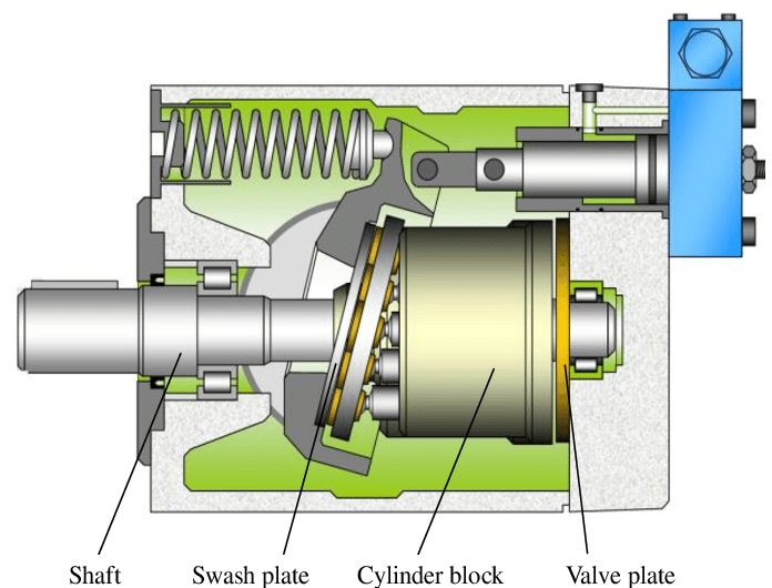
An axial piston pump features four major components: a shaft, swashplate or bent axis, cylinder block, and valve plate. The cylinder block houses the piston pumps, which are laid out cyclically around the drive shaft’s axis (thus why it is named anaxialpiston pump).
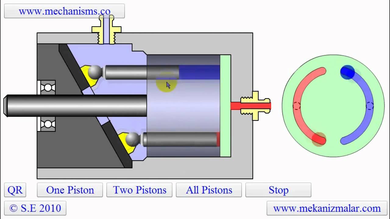
The pistons in the cylinder block pump up and down as the drive shaft rotates. The piston’s stroke will vary depending on how it is angled in the swashplate or bent axis. As the pistons move in one direction, they are connected to a suction line, and when they move in the opposite direction, they connect to a discharge channel, allowing a continuous flow of fluid.
The design of a radial piston pump is significantly different from an axial pump. The radial piston pump consists of a cylinder block, rotating camshaft, and pistons. The pistons are arranged around the cylinder block in a radial pattern and diverge from the camshaft like rays. The rotation of the cam causes the pistons to change from suction to discharge and vice versa.
In general, choosing a hydraulic pump requires an application evaluation. You’ll need to know pressure requirements, desired flow rate, speed, horsepower, and the type of fluid the pump will be dispersing.
Radial piston pumps can usually handle all fluids, including mineral oil and water-glycol hydraulic fluid, while axial piston pumps are preferred for extremely high-pressure applications.
Although piston pumps are highly efficient and reliable, contamination, over-pressurization, and inlet blockages can cause the pump to fail. If and when this happens, you’ll need to replace your pump as soon as possible.
When choosing a replacement pump, you’ll have to choose between a direct OEM replacement and a remanufactured pump. Unfortunately, direct OEM replacement pumps and services can be a significant investment. Additionally, if you have outdated equipment, you may not be able to find thepump partsneeded to restore your equipment.
If you’re looking for a quick and relatively inexpensive solution, a remanufactured pump is your best choice. However, if time and money aren’t an issue, a direct OEM replacement will most likely be the best option if the manufacturer hasn’t discontinued the pump.
Do you need help finding the right piston pump? Turn to Panagon Systems. Founded over 25 years ago, we’re an industry-leading remanufacturer of hydraulic piston pumps and motors. We specialize in remanufacturing pumps from brands like Vickers/Eaton, Rexroth, and Caterpillar, and we also carry. All pumps and motors are remanufactured in-house in the United States, guaranteed to meet OEM specifications, and are backed by a one-year warranty.
Piston pumps are durable and relatively simple devices. A basic piston pump is made up of a piston, a chamber, and two valves. The pump operates by driving the piston down into the chamber, thereby compressing the media inside. In a hand pump, this is usually air. Once the pressure of the air exceeds that of the outlet valve spring, the compressed media goes through the open outlet valve. When the piston is drawn back up, it opens the inlet valve and closes the outlet valve, thereby utilizing suction to draw in new media for compression.
Although somewhat expensive, piston pumps are among the most efficient types of pumps. They have an excellent pressure rating (as high as 10,000 psi), but their design makes them susceptible to contaminants. They provide an excellent solution for many high-pressure hydraulic oil pumping applications.
Axial piston pumps are positive displacement pumps that use multiple cylinders grouped around a central axis. The group of cylinders, usually containing an odd number, is called a cylinder block. The pistons within each cylinder are attached to a swashplate. The swashplate is also known as a cam or wobble plate and attaches to a rotating shaft. As the shaft turns, the angle of the swashplate changes, which drives the pistons in and out of their respective cylinders.
Since the swashplate is at an angle to the axis of rotation, the pistons must reciprocate axially as they orbit around the cylinder block axis. The axial motion of the pistons is sinusoidal. As a piston rises, it moves toward the valve plate. At this point in the rotation, the fluid trapped between the buried end of the piston and the valve plate is expelled to the pump"s discharge port through one of the valve plate"s semi-circular ports. As the piston moves back toward the valve plate, the fluid is pushed through the discharge port of the valve plate.
Axial piston pumps can be designed as variable displacement piston pumps, making them very useful for controlling the speeds of hydraulic motors and cylinders. In this design, a swashplate is used to vary the depth to which each piston extends into its cylinder as the pump rotates, affecting the volume of discharge. A pressure compensator piston is used in some designs to maintain a constant discharge pressure under varying loads. Cheaper pressure washers sometimes use fixed-rate designs.
In a typical pressure-compensated pump, the swashplate angle adjusts through the action of a valve using pressure feedback to make sure that the pump output flow is precisely enough to maintain a designated pressure. If the load flow increases, the pressure momentarily decreases, but the pressure-compensation valve senses the decrease and then increases the swashplate angle to increase the pump’s output flow, restoring the desired pressure.
Axial piston pumps can contain most of the necessary circuit controls intrinsically by controlling the swash-plate angle, to regulate flow and pressure. They are very reliable and can allow the rest of the hydraulic system to which they’re attached to be very simple and inexpensive.
They are used to power the hydraulic systems of jet aircrafts, being gear-driven off of the turbine engine"s main shaft, and are often used for automotive air conditioning compressors for cabin cooling. The design of these pumps meets the limited weight and space requirement in the vehicle"s engine bay and reduces vibrations.
Pressure washers also use these pumps, and axial reciprocating motors are used to power many machines. They operate on the same principles as axial piston pumps, except that the circulating fluid is provided under substantial pressure and the piston housing rotates and provides shaft power to another machine. A typical use of an axial reciprocating motor is powering small earthmoving machines such as skid loader machines.
This guide provides a basic understanding of axial piston pumps. To find out more about other types of pumps, read our guide here. For more information on related products, consult our other product guides or visit the Thomas Supplier Discovery Platform to locate potential sources or view details on specific products.

This website is using a security service to protect itself from online attacks. The action you just performed triggered the security solution. There are several actions that could trigger this block including submitting a certain word or phrase, a SQL command or malformed data.

A piston pump is a type of positive displacement pump where the high-pressure seal reciprocates with the piston.liquids or compress gases. They can operate over a wide range of pressures. High pressure operation can be achieved without adversely affecting flow rate. Piston pumps can also deal with viscous media and media containing solid particles.
In a lift pump, the upstroke of the piston draws water, through a valve, into the lower part of the cylinder. On the downstroke, water passes through valves set in the piston into the upper part of the cylinder. On the next upstroke, water is discharged from the upper part of the cylinder via a spout. This type of pump is limited by the height of water that can be supported by air pressure against a vacuum.
In a force pump, the upstroke of the piston draws water, through an inlet valve, into the cylinder. On the downstroke, the water is discharged, through an outlet valve, into the outlet pipe.
Hydraulic piston pumps can handle large flows at high hydraulic system pressures. The piston pump is a hydraulic pump that delivers optimum efficiency and reliability while maintaining a compact size with a high power density. In these pumps, the pistons accurately slide back and forth inside the cylinders that are part of the hydraulic pump. The sealing properties of the pistons are excellent which makes it possible to operate at high pressures with low fluid leakage.
Hydraulic piston pumps operate at very high volumetric efficiency levels due to low fluid leakage. The plungers may consist of valves at the suction and pressure ports or with input and output channels. Piston pumps with valves at the ports are better suited to operate at higher system pressures due to better sealing characteristics. Applications are mobile and construction equipment, marine auxiliary power, metal forming and stamping, machine tools and oil field equipment.
Hydraulic pumps are manufactured depending on different functional and hydraulic system requirements, such as operating medium, required range of pressure, type of drive, etc. Our sales engineers will assist you in selecting the most appropriate hydraulic pump for your application. Contact DTA for your hydraulic pump needs today!

Hydraulic pumps are primarily designed to convert incoming prime mover energy into hydraulic energy, manifested as pressure and flow. The term hydrostaticrefers to a state of pressure equilibrium, especially in a confined space. All traditional hydraulic applications are hydrostatic, and in most cases, if you shut down the pump, physical loads should hold fast using the already pressurized hydraulic oil.
It would be easy if everyone used hydraulic pumps for hydraulic applications, but not everyone seems to like things easy. For example, I can think of a dozen ways to lubricate a CNC machine or large bearing, and even if the lubrication medium was hydraulic fluid, I could think of better pump designs for this application. Still, some spindles require hydrostatic bearing support for very high-speed machining, so sometimes high-pressure hydraulic fluid is the only solution.
You’d be surprised to know how often hydraulic pumps are used for water-based coolant for CNC machines. Although hydrostatic bearings absolutely require high pressure to support the assembly, using them for coolant is a surprising take on the pressure compensated pump. Dynamic pumps use impellers to essentially throw the fluid to create inertial pressure, much like the impeller on a boat. You can cap the outlet port of a dynamic pump just the same as you can a pressure compensated piston pump.
I suppose engineers started using pressure compensated pumps for cooling because of their ability to maintain a set pressure even when downstream flow paths wear, such as with orifices inside of tooling. Through-tool coolant will slowly erode the internal diameter of its flow path, which increases the effective orifice size, thereby reducing pressure drop. So long as the pump is oversized for the application, it will maintain the pressure compensation set point despite downstream increases in orifice size (to a point).
However, there are right and wrong ways to use hydraulic pumps for lubrication and coolant. For example, variable displacement axial piston pumps are overbuilt for these applications, mainly because they handle thousands more psi than any lubrication or coolant application needs. At the same time, these pumps actually require a minimumoperating pressure.
Although minimum compensator pressure depends on the make and construction of the pump, expect minimum pressure of at least 200-300 psi. Unlike gear pumps, for example, the pressure compensated pump has many parts engineered to operate effectively only when pressure exists. For example, the compensator, control piston, and (sometimes) the bias piston run from pilot pressure, but pressure is required to keep the entire pump under tension.
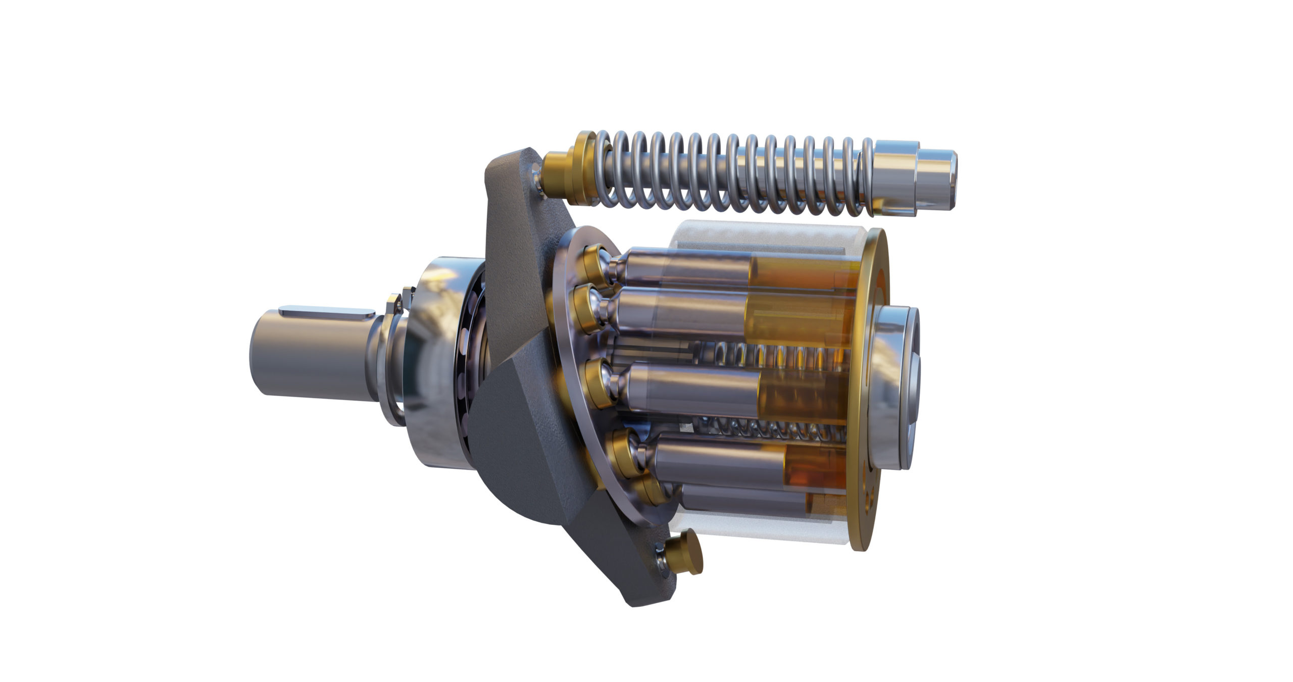
Refer to the image, which shows the major components of the pump’s rotating group. As the blue cylinder block rotates, the swashplate angle forces the pistons to reciprocate, which in turn pumps fluid. As the piston passes “top dead center” and begins to retract into the block to create pressure, the entire assembly maintains tension until the piston again extends to suck in the fluid.
Without pressure, there exists no tension in the rotating group. With no tension, the entire assembly is a floppy collection of metal parts banging and slapping as they reciprocate and rotate at maximum displacement because no hydraulic pressure exists to bring the pump on standby. Hydraulic oil feeds typically down through the hollow pistons where a pinhole in the socket feeds pilot pressure to keep the slippers lubricated against the swashplate, but with no standby pressure, no lubrication occurs.
If you are using, or are considering using, a hydraulic pump for your lubrication or coolant application, you must guarantee your pump never drops below its minimum pressure rating. This may occur from orifice wear, but I’ve also seen hydraulic circuits designed to “unload” the pump when coolant isn’t required. You’re better off installing a poppet valve to block outlet flow than to unload the pump because only running with no oil will damage a pump faster.

The goal of a hydraulic pump is to move hydraulic fluid through a hydraulic system, acting much like the beating heart of the system. There are two things that all hydraulic pumps have in common: (1) they provide hydraulic flow to other components (e.g., rams, hydraulic motors, cylinder) within a hydraulic system, and (2) they produce flow which in turn generates pressure when there is a resistance to flow. In addition, most hydraulic pumps are motor-driven and include a pressure relief valve as a type of overpressure protection. The three most common types of hydraulic pumps currently in use are gear, piston, and vane pumps.
In a gear pump, hydraulic fluid is trapped between the body of the pump and the areas between the teeth of the pump’s two meshing gears. The driveshaft is used to power one gear while the other remains idle until it meshes with the driving gear. These pumps are what is known as fixed displacement or positive displacement because each rotation of the shaft displaces the same amount of hydraulic fluid at the same pressure. There are two basic types of gear pumps, external and internal, which will be discussed in a moment.
Gear pumps are compact, making them ideal for applications that involve limited space. They are also simple in design, making them easier to repair and maintain. Note that gear pumps usually exhibit the highest efficiency when running at their maximum speed. In general, external gear pumps can produce higher levels of pressure (up to 3,000 psi) and greater throughput than vane pumps.
External gear pumps are often found in close-coupled designs where the gear pump and the hydraulic motor share the same mounting and the same shaft. In an external gear pump, fluid flow occurs around the outside of a pair of meshed external spur gears. The hydraulic fluid moves between the housing of the pump and the gears to create the alternating suction and discharge needed for fluid flow.
External gear pumps can provide very high pressures (up to 3,000 psi), operate at high speeds (3,000 rpm), and run more quietly than internal gear pumps. When gear pumps are designed to handle even higher pressures and speeds, however, they will be very noisy and there may be special precautions that must be made.
External gear pumps are often used in powerlifting applications, as well as areas where electrical equipment would be either too bulky, inconvenient, or costly. External gear pumps can also be found on some agricultural and construction equipment to power their hydraulic systems.
In an internal gear pump, the meshing action of external and internal gears works with a crescent-shaped sector element to generate fluid flow. The outer gear has teeth pointing inwards and the inner gear has teeth pointing outward. As these gears rotate and come in and out of mesh, they create suction and discharge zones with the sector acting as a barrier between these zones. A gerotor is a special type of internal gear pump that eliminates the need for a sector element by using trochoidal gears to create suction and discharge zones.
Unlike external gear pumps, internal gear pumps are not meant for high-pressure applications; however, they do generate flow with very little pulsation present. They are not as widely used in hydraulics as external gear pumps; however, they are used with lube oils and fuel oils and work well for metering applications.
In a piston pump, reciprocating pistons are used to alternately generate suction and discharge. There are two different ways to categorize piston pumps: whether their piston is axially or radially mounted and whether their displacement is fixed or variable.
Piston pumps can handle higher pressures than gear or vane pumps even with comparable displacements, but they tend to be more expensive in terms of the initial cost. They are also more sensitive to contamination, but following strict hydraulic cleanliness guidelines and filtering any hydraulic fluid added to the system can address most contamination issues.
In an axial piston pump, sometimes called an inline axial pump, the pistons are aligned with the axis of the pump and arranged within a circular cylinder block. On one side of the cylinder block are the inlet and outlet ports, while an angled swashplate lies on the other side. As the cylinder block rotates, the pistons move in and out of the cylinder block, thus creating alternating suction and discharge of hydraulic fluid.
Axial piston pumps are ideal for high-pressure, high-volume applications and can often be found powering mission-critical hydraulic systems such as those of jet aircraft.
In a bent-axis piston pump (which many consider a subtype of the axial piston pump), the pump is made up of two sides that meet at an angle. On one side, the drive shaft turns the cylinder block that contains the pistons which match up to bores on the other side of the pump. As the cylinder block rotates, the distances between the pistons and the valving surface vary, thus achieving the necessary suction and discharge.
In a radial piston pump, the pistons lie perpendicular to the axis of the pump and are arranged radially like spokes on a wheel around an eccentrically placed cam. When the drive shaft rotates, the cam moves and pushes the spring-loaded pistons inward as it passes them. Each of these pistons has its own inlet and outlet ports that lead to a chamber. Within this chamber are valves that control the release and intake of hydraulic fluid.
In a fixed displacement pump, the amount of fluid discharged in each reciprocation is the same volume. However, in a variable displacement pump, a change to the angle of the adjustable swashplate can increase or reduce the volume of fluid discharged. This design allows you to vary system speed without having to change engine speed.
When the input shaft of a vane pump rotates, rigid vanes mounted on an eccentric rotor pick up hydraulic fluid and transport it to the outlet of the pump. The area between the vanes increases on the inlet side as hydraulic fluid is drawn inside the pump and decreases on the outlet side to expel the hydraulic fluid through the output port. Vane pumps can be either fixed or variable displacement, as discussed for piston pumps.
Vane pumps are used in utility vehicles (such as those with aerial ladders or buckets) but are not as common today, having been replaced by gear pumps. This does not mean, however, that they are not still in use. They are not designed to handle high pressures but they can generate a good vacuum and even run dry for short periods of time.
There are other key aspects to choosing the right hydraulic pump that goes beyond deciding what type is best adapted to your application. These pump characteristics include the following:
Selecting a pump can be very challenging, but a good place to start is looking at the type of pump that you need. Vane pumps have been largely replaced by compact, durable gear pumps, with external gear pumps working best for high pressure and operating speeds while internal gear pumps are able to generate flow with very little pulsation. However, vane pumps are still good for creating an effective vacuum and can run even when dry for short periods of time. Piston pumps in general are more powerful but, at the same time, more susceptible to contamination.
Whether the pump is needed for the rugged world of mining, the sterile world of food and beverage processing, or the mission-critical aerospace industry, MAC Hydraulics can assist you with selecting, installing, maintaining, and repairing the right pump to meet the needs of your hydraulic system. In the event of a breakdown, our highly skilled technicians can troubleshoot and repair your pump — no matter who the manufacturer happens to be. We also offer on-site services that include common repairs, preventative maintenance, lubrication, cleaning, pressure testing, and setting.

The piston pump is strong, as well as simple devices. These pumps are made with a chamber, a piston, and a couple of control devices. These pumps function by flowing downward into the chamber, thus reducing the media within a hand pump. When the air pressure surpasses from the opening valve spring, then the reduced media can be sent throughout the open exit valve. As the piston is drawn back-up, then it releases the inlet valve & shuts the outlet valve, thus suction can be used to draw in extra media for compression. This article discusses an overview of piston-pump, working, types, etc.
The piston pump can be defined as it is a positive displacement pump. These pumps use a piston, diaphragm, otherwise plunger for moving liquids. These pumps use check valves as the input and output valves. The general piston-pump is a rotary pump which uses a wheel or revolving shaft for operating the piston.
The revolvingcomponent can be connected to a shaft from its center, and this shaft can be connected to the piston. When the revolving component twists, it runs the shaft as well as piston down to pull it back.
The piston pump working is similar to PD pumps. Because they work with the help of the pumping mechanism force to increase the volume of the liquid. These pumps can use the power from power sources.
These pumps include more than one piston with a set of control devices. The duplex pump includes two pistons as well as two controlling devices. Similarly, a triplex pump includes three pistons as well as three controlling devices. It is very important to check the controlling devices on both sides to ensure that the flow of liquid direction at both sides is flowing or not.
These pumps are single otherwise double acting pumps. Double acting pumps involve two sets of controlling devices & liquid on both ends. This lets the pump to complete a pumping cycle by flowing in one direction to other. When the piston is taking in one direction, then it will exhaust at another side. This pump needs solo action versions for flowing in both directions for completing a cycle.
These pumps are classified into different types namely lift pump, a force pump, axial pump, and radial piston-pump. From these pumps, lift and force pumps can operate manually otherwise with the help of an engine.
In this type of pump, the piston above stroke can draw fluid with the help of a control device which is named as valve into the below portion of the cylinder.
On the below stroke, fluid flows through control devices which are arranged in the piston into the higher portion of the cylinder. After that on the upstroke, fluid can be released from the higher portion of the cylinder through a spout.
In this type of pump, the piston pumps upstroke can draw fluid throughout an inlet valve to the cylinder (tube). On top of the downstroke, the fluid level can be discharged via an exit valve into the outlet tube.
This is pump is a PD (positive displacement) pump and it has several pistons within a circular array of a tube block. This block can be driven to turn its symmetry axis with an important shaft which is associated with the pumping pistons. These pumps can be used like an automotive air conditioning compressor, a separate pump, otherwise a hydraulic motor.
This pump is one kind of hydraulic pump, and the working pistons expand within a radial track symmetrically in the region of the drive shaft, in disparity in the direction of the axial piston pump.
The main specifications while choosing these pumps mainly include the rate of flow, head of the pump, volume stroke, pressure, outlet diameter, power rating, horsepower, and finally operating temperature.
The materials used to design the piston-pump mainly depend on the application of a pump. The casing and cylinder materials must have sufficient strength as well as they have to hold up adjacent to the operating environment conditions. Materials to get in touch with the pumped media require to resistant for any rust-induced with the liquid. Some type of materials used in this pump is discussed below.
Stainless steel alloys and steel give safety against rust and chemical and they have superior tensile powers compare with plastics, equivalent to superior pressure ratings.
Thus, this is all about piston pumps which are used like hydraulic pumps for powering heavy machines as well as small machines. Piston pump applications mainly include transferring paint, pastry, chocolate, etc. The size of these pipes has increased for utilizing in industries. All types of piston-pumps in the form of radial and axial are also used in advanced industrial applications, which include numerous pistons arranged within a round cylinder block. Here is a question for you, what are the parts of the piston pump?

Check that the electric motor is running. Although this is a simple concept, before you begin replacing parts, it’s critical that you make sure the electric motor is running. This can often be one of the easiest aspects to overlook, but it is necessary to confirm before moving forward.
Check that the pump shaft is rotating. Even though coupling guards and C-face mounts can make this difficult to confirm, it is important to establish if your pump shaft is rotating. If it isn’t, this could be an indication of a more severe issue, and this should be investigated immediately.
Check the oil level. This one tends to be the more obvious check, as it is often one of the only factors inspected before the pump is changed. The oil level should be three inches above the pump suction. Otherwise, a vortex can form in the reservoir, allowing air into the pump.
If the oil level is low, determine where the leak is in the system. Although this can be a difficult process, it is necessary to ensure your machines are performing properly. Leaks can be difficult to find.
What does the pump sound like when it is operating normally? Vane pumps generally are quieter than piston and gear pumps. If the pump has a high-pitched whining sound, it most likely is cavitating. If it has a knocking sound, like marbles rattling around, then aeration is the likely cause.
Cavitation is the formation and collapse of air cavities in the liquid. When the pump cannot get the total volume of oil it needs, cavitation occurs. Hydraulic oil contains approximately nine percent dissolved air. When the pump does not receive adequate oil volume at its suction port, high vacuum pressure occurs.
This dissolved air is pulled out of the oil on the suction side and then collapses or implodes on the pressure side. The implosions produce a very steady, high-pitched sound. As the air bubbles collapse, the inside of the pump is damaged.
While cavitation is a devastating development, with proper preventative maintenance practices and a quality monitoring system, early detection and deterrence remain attainable goals. UE System’s UltraTrak 850S CD pump cavitation sensor is a Smart Analog Sensor designed and optimized to detect cavitation on pumps earlier by measuring the ultrasound produced as cavitation starts to develop early-onset bubbles in the pump. By continuously monitoring the impact caused by cavitation, the system provides a simple, single value to trend and alert when cavitation is occurring.
The oil viscosity is too high. Low oil temperature increases the oil viscosity, making it harder for the oil to reach the pump. Most hydraulic systems should not be started with the oil any colder than 40°F and should not be put under load until the oil is at least 70°F.
Many reservoirs do not have heaters, particularly in the South. Even when heaters are available, they are often disconnected. While the damage may not be immediate, if a pump is continually started up when the oil is too cold, the pump will fail prematurely.
The suction filter or strainer is contaminated. A strainer is typically 74 or 149 microns in size and is used to keep “large” particles out of the pump. The strainer may be located inside or outside the reservoir. Strainers located inside the reservoir are out of sight and out of mind. Many times, maintenance personnel are not even aware that there is a strainer in the reservoir.
The suction strainer should be removed from the line or reservoir and cleaned a minimum of once a year. Years ago, a plant sought out help to troubleshoot a system that had already had five pumps changed within a single week. Upon closer inspection, it was discovered that the breather cap was missing, allowing dirty air to flow directly into the reservoir.
A check of the hydraulic schematic showed a strainer in the suction line inside the tank. When the strainer was removed, a shop rag was found wrapped around the screen mesh. Apparently, someone had used the rag to plug the breather cap opening, and it had then fallen into the tank. Contamination can come from a variety of different sources, so it pays to be vigilant and responsible with our practices and reliability measures.
The electric motor is driving the hydraulic pump at a speed that is higher than the pump’s rating. All pumps have a recommended maximum drive speed. If the speed is too high, a higher volume of oil will be needed at the suction port.
Due to the size of the suction port, adequate oil cannot fill the suction cavity in the pump, resulting in cavitation. Although this rarely happens, some pumps are rated at a maximum drive speed of 1,200 revolutions per minute (RPM), while others have a maximum speed of 3,600 RPM. The drive speed should be checked any time a pump is replaced with a different brand or model.
Every one of these devastating causes of cavitation threatens to cause major, irreversible damage to your equipment. Therefore, it’s not only critical to have proper, proactive practices in place, but also a monitoring system that can continuously protect your valuable assets, such as UE System’s UltraTrak 850S CD pump cavitation senor. These sensors regularly monitor the health of your pumps and alert you immediately if cavitation symptoms are present, allowing you to take corrective action before it’s too late.
Aeration is sometimes known as pseudo cavitation because air is entering the pump suction cavity. However, the causes of aeration are entirely different than that of cavitation. While cavitation pulls air out of the oil, aeration is the result of outside air entering the pump’s suction line.
Several factors can cause aeration, including an air leak in the suction line. This could be in the form of a loose connection, a cracked line, or an improper fitting seal. One method of finding the leak is to squirt oil around the suction line fittings. The fluid will be momentarily drawn into the suction line, and the knocking sound inside the pump will stop for a short period of time once the airflow path is found.
A bad shaft seal can also cause aeration if the system is supplied by one or more fixed displacement pumps. Oil that bypasses inside a fixed displacement pump is ported back to the suction port. If the shaft seal is worn or damaged, air can flow through the seal and into the pump’s suction cavity.
As mentioned previously, if the oil level is too low, oil can enter the suction line and flow into the pump. Therefore, always check the oil level with all cylinders in the retracted position.
If a new pump is installed and pressure will not build, the shaft may be rotating in the wrong direction. Some gear pumps can be rotated in either direction, but most have an arrow on the housing indicating the direction of rotation, as depicted in Figure 2.
Pump rotation should always be viewed from the shaft end. If the pump is rotated in the wrong direction, adequate fluid will not fill the suction port due to the pump’s internal design.
A fixed displacement pump delivers a constant volume of oil for a given shaft speed. A relief valve must be included downstream of the pump to limit the maximum pressure in the system.
After the visual and sound checks are made, the next step is to determine whether you have a volume or pressure problem. If the pressure will not build to the desired level, isolate the pump and relief valve from the system. This can be done by closing a valve, plugging the line downstream, or blocking the relief valve. If the pressure builds when this is done, there is a component downstream of the isolation point that is bypassing. If the pressure does not build up, the pump or relief valve is bad.
If the system is operating at a slower speed, a volume problem exists. Pumps wear over time, which results in less oil being delivered. While a flow meter can be installed in the pump’s outlet line, this is not always practical, as the proper fittings and adapters may not be available. To determine if the pump is badly worn and bypassing, first check the current to the electric motor. If possible, this test should be made when the pump is new to establish a reference. Electric motor horsepower is relative to the hydraulic horsepower required by the system.
For example, if a 50-GPM pump is used and the maximum pressure is 1,500 psi, a 50-hp motor will be required. If the pump is delivering less oil than when it was new, the current to drive the pump will drop. A 230-volt, 50-hp motor has an average full load rating of 130 amps. If the amperage is considerably lower, the pump is most likely bypassing and should be changed.
Figure 4.To isolate a fixed displacement pump and relief valve from the system, close a valve or plug the line downstream (left). If pressure builds, a component downstream of the isolation point is bypassing (right).
The most common type of variable displacement pump is the pressure-compensating design. The compensator setting limits the maximum pressure at the pump’s outlet port. The pump should be isolated as described for the fixed displacement pump.
If pressure does not build up, the relief valve or pump compensator may be bad. Prior to checking either component, perform the necessary lockout procedures and verify that the pressure at the outlet port is zero psi. The relief valve and compensator can then be taken apart and checked for contamination, wear, and broken springs.
Check the tank line temperature of the relief valve with a temperature gun or infrared camera. The tank line should be near ambient temperature. If the line is hot, the relief valve is either stuck partially open or is set too low.
Install a flow meter in the case drain line and check the flow rate. Most variable displacement pumps bypass one to three percent of the maximum pump volume through the case drain line. If the flow rate reaches 10 percent, the pump should be changed. Permanently installing a flow meter in the case drain line is an excellent reliability and troubleshooting tool.
Ensure the compensator is 200 psi above the maximum load pressure. If set too low, the compensator spool will shift and start reducing the pump volume when the system is calling for maximum volume.
Performing these recommended tests should help you make good decisions about the condition of your pumps or the cause of pump failures. If you change a pump, have a reason for changing it. Don’t just do it because you have a spare one in stock.
Conduct a reliability assessment on each of your hydraulic systems so when an issue occurs, you will have current pressure and temperature readings to consult.
Al Smiley is the president of GPM Hydraulic Consulting Inc., located in Monroe, Georgia. Since 1994, GPM has provided hydraulic training, consulting and reliability assessments to companies in t...

There are typically three types of hydraulic pump constructions found in mobile hydraulic applications. These include gear, piston, and vane; however, there are also clutch pumps, dump pumps, and pumps for refuse vehicles such as dry valve pumps and Muncie Power Products’ Live PakTM.
The hydraulic pump is the component of the hydraulic system that takes mechanical energy and converts it into fluid energy in the form of oil flow. This mechanical energy is taken from what is called the prime mover (a turning force) such as the power take-off or directly from the truck engine.
With each hydraulic pump, the pump will be of either a uni-rotational or bi-rotational design. As its name implies, a uni-rotational pump is designed to operate in one direction of shaft rotation. On the other hand, a bi-rotational pump has the ability to operate in either direction.
For truck-mounted hydraulic systems, the most common design in use is the gear pump. This design is characterized as having fewer moving parts, being easy to service, more tolerant of contamination than other designs and relatively inexpensive. Gear pumps are fixed displacement, also called positive displacement, pumps. This means the same volume of flow is produced with each rotation of the pump’s shaft. Gear pumps are rated in terms of the pump’s maximum pressure rating, cubic inch displacement and maximum input speed limitation.
Generally, gear pumps are used in open center hydraulic systems. Gear pumps trap oil in the areas between the teeth of the pump’s two gears and the body of the pump, transport it around the circumference of the gear cavity and then force it through the outlet port as the gears mesh. Behind the brass alloy thrust plates, or wear plates, a small amount of pressurized oil pushes the plates tightly against the gear ends to improve pump efficiency.
A cylinder block containing pistons that move in and out is housed within a piston pump. It’s the movement of these pistons that draw oil from the supply port and then force it through the outlet. The angle of the swash plate, which the slipper end of the piston rides against, determines the length of the piston’s stroke. While the swash plate remains stationary, the cylinder block, encompassing the pistons, rotates with the pump’s input shaft. The pump displacement is then determined by the total volume of the pump’s cylinders. Fixed and variable displacement designs are both available.
With a fixed displacement piston pump, the swash plate is nonadjustable. Its proportional output flow to input shaft speed is like that of a gear pump and like a gear pump, the fixed displacement piston pump is used within open center hydraulic systems.
As previously mentioned, piston pumps are also used within applications like snow and ice control where it may be desirable to vary system flow without varying engine speed. This is where the variable displacement piston pump comes into play – when the hydraulic flow requirements will vary based on operating conditions. Unlike the fixed displacement design, the swash plate is not fixed and its angle can be adjusted by a pressure signal from the directional valve via a compensator.
Flow and Pressure Compensated Combined – These systems with flow and pressure compensation combined are often called a load-sensing system, which is common for snow and ice control vehicles.
Vane pumps were, at one time, commonly used on utility vehicles such as aerial buckets and ladders. Today, the vane pump is not commonly found on these mobile (truck-mounted) hydraulic systems as gear pumps are more widely accepted and available.
Within a vane pump, as the input shaft rotates it causes oil to be picked up between the vanes of the pump which is then transported to the pump’s outlet side. This is similar to how gear pumps work, but there is one set of vanes – versus a pair of gears – on a rotating cartridge in the pump housing. As the area between the vanes decreases on the outlet side and increases on the inlet side of the pump, oil is drawn in through the supply port and expelled through the outlet as the vane cartridge rotates due to the change in area.
Input shaft rotates, causing oil to be picked up between the vanes of the pump which is then transported to pump outlet side as area between vanes decreases on outlet side and increases on inlet side to draw oil through supply port and expel though outlet as vane cartridge rotates
A clutch pump is a small displacement gear pump equipped with a belt-driven, electromagnetic clutch, much like that found on a car’s air conditioner compressor. It is engaged when the operator turns on a switch inside the truck cab. Clutch pumps are frequently used where a transmission power take-off aperture is not provided or is not easily accessible. Common applications include aerial bucket trucks, wreckers and hay spikes. As a general rule clutch pumps cannot be used where pump output flows are in excess of 15 GPM as the engine drive belt is subject to slipping under higher loads.
What separates this pump from the traditional gear pump is its built-in pressure relief assembly and an integral three-position, three-way directional control valve. The dump pump is unsuited for continuous-duty applications because of its narrow, internal paths and the subsequent likelihood of excessive heat generation.
Dump pumps are often direct mounted to the power take-off; however, it is vital that the direct-coupled pumps be rigidly supported with an installer-supplied bracket to the transmission case with the pump’s weight at 70 lbs. With a dump pump, either a two- or three-line installation must be selected (two-line and three-line refer to the number of hoses used to plumb the pump); however, a dump pump can easily be converted from a two- to three-line installation. This is accomplished by inserting an inexpensive sleeve into the pump’s inlet port and uncapping the return port.
Many dump bodies can function adequately with a two-line installation if not left operating too long in neutral. When left operating in neutral for too long however, the most common dump pump failure occurs due to high temperatures. To prevent this failure, a three-line installation can be selected – which also provides additional benefits.
Pumps for refuse equipment include both dry valve and Live Pak pumps. Both conserve fuel while in the OFF mode, but have the ability to provide full flow when work is required. While both have designs based on that of standard gear pumps, the dry valve and Like Pak pumps incorporate additional, special valving.
Primarily used on refuse equipment, dry valve pumps are large displacement, front crankshaft-driven pumps. The dry valve pump encompasses a plunger-type valve in the pump inlet port. This special plunger-type valve restricts flow in the OFF mode and allows full flow in the ON mode. As a result, the horsepower draw is lowered, which saves fuel when the hydraulic system is not in use.
In the closed position, the dry valve allows just enough oil to pass through to maintain lubrication of the pump. This oil is then returned to the reservoir through a bleed valve and small return line. A bleed valve that is fully functioning is critical to the life of this type of pump, as pump failure induced by cavitation will result if the bleed valve becomes clogged by contaminates. Muncie Power Products also offer a butterfly-style dry valve, which eliminates the bleed valve requirement and allows for improved system efficiency.
It’s important to note that with the dry valve, wear plates and shaft seals differ from standard gear pumps. Trying to fit a standard gear pump to a dry valve likely will result in premature pump failure.
Encompasses plunger-type valve in the pump inlet port restricting flow in OFF mode, but allows full flow in ON mode lowering horsepower draw to save fuel when not in use
Wear plates and shaft seals differ from standard gear pumps – trying to fit standard gear pump to dry valve likely will result in premature pump failure
Live Pak pumps are also primarily used on refuse equipment and are engine crankshaft driven; however, the inlet on a Live Pak pump is not outfitted with a shut-off valve. With a Live Pak pump, the outlet incorporates a flow limiting valve. This is called a Live Pak valve. The valve acts as an unloading valve in OFF mode and a flow limiting valve in the ON mode. As a result, the hydraulic system speed is limited to keep within safe operating parameters.
Outlet incorporates flow limiting valve called Live Pak valve – acts as an unloading valve in OFF mode and flow limiting valve in ON mode restricting hydraulic system speed to keep within safe operating parameters
This website is using a security service to protect itself from online attacks. The action you just performed triggered the security solution. There are several actions that could trigger this block including submitting a certain word or phrase, a SQL command or malformed data.


 8613371530291