
piston hydraulic pump how it works made in china

This website is using a security service to protect itself from online attacks. The action you just performed triggered the security solution. There are several actions that could trigger this block including submitting a certain word or phrase, a SQL command or malformed data.

This website is using a security service to protect itself from online attacks. The action you just performed triggered the security solution. There are several actions that could trigger this block including submitting a certain word or phrase, a SQL command or malformed data.
A hydraulic pump is a mechanical device that converts mechanical power into hydraulic energy. It generates flow with enough power to overcome pressure induced by the load.
A hydraulic pump performs two functions when it operates. Firstly, its mechanical action creates a vacuum at the pump inlet, subsequently allowing atmospheric pressure to force liquid from the reservoir and then pumping it through to the inlet line of the pump. Secondly, its mechanical action delivers this liquid to the pump outlet and forces it into the hydraulic system.
The three most common hydraulic pump designs are: vane pump, gear pump and radial piston pump. All are well suited to common hydraulic uses, however the piston design is recommended for higher pressures.
Most pumps used in hydraulic systems are positive-displacement pumps. This means that they displace (deliver) the same amount of liquid for each rotating cycle of the pumping element. The delivery per cycle remains almost constant, regardless of changes in pressure.
Positive-displacement pumps are grouped into fixed or variable displacement. A fixed displacement pump’s output remains constant during each pumping cycle and at a given pump speed. Altering the geometry of the displacement chamber changes the variable displacement pump’s output.
Fixed displacement pumps (or screw pumps) make little noise, so they are perfect for use in for example theatres and opera houses. Variable displacement pumps, on the other hand, are particularly well suited in circuits using hydraulic motors and where variable speeds or the ability to reverse is needed.
Applications commonly using a piston pump include: marine auxiliary power, machine tools, mobile and construction equipment, metal forming and oil field equipment.
As the name suggests, a piston pump operates through pistons that move back and forth in the cylinders connected to the hydraulic pump. A piston pump also has excellent sealing capabilities.
A hydraulic piston pump can operate at large volumetric levels thanks to low oil leakage. Some plungers require valves at the suction and pressure ports, whilst others require them with the input and output channels. Valves (and their sealing properties) at the end of the piston pumps will further enhance the performance at higher pressures.
The axial piston pump is possibly the most widely used variable displacement pump. It’s used in everything from heavy industrial to mobile applications. Different compensation techniques will continuously alter the pump’s fluid discharge per revolution. And moreover, also alter the system pressure based on load requirements, maximum pressure cut-off settings and ratio control. This implies significant power savings.
Two principles characterise the axial piston pump. Firstly the swash plate or bent axis design and secondly the system parameters. System parameters include the decision on whether or not the pump is used in an open or closed circuit.
The return line in a closed loop circuit is under constant pressure. This must be considered when designing an axial piston pump that is used in a closed loop circuit. It is also very important that a variable displacement volume pump is installed and operates alongside the axial piston pump in the systems. Axial piston pumps can interchange between a pump and a motor in some fixed displacement configurations.
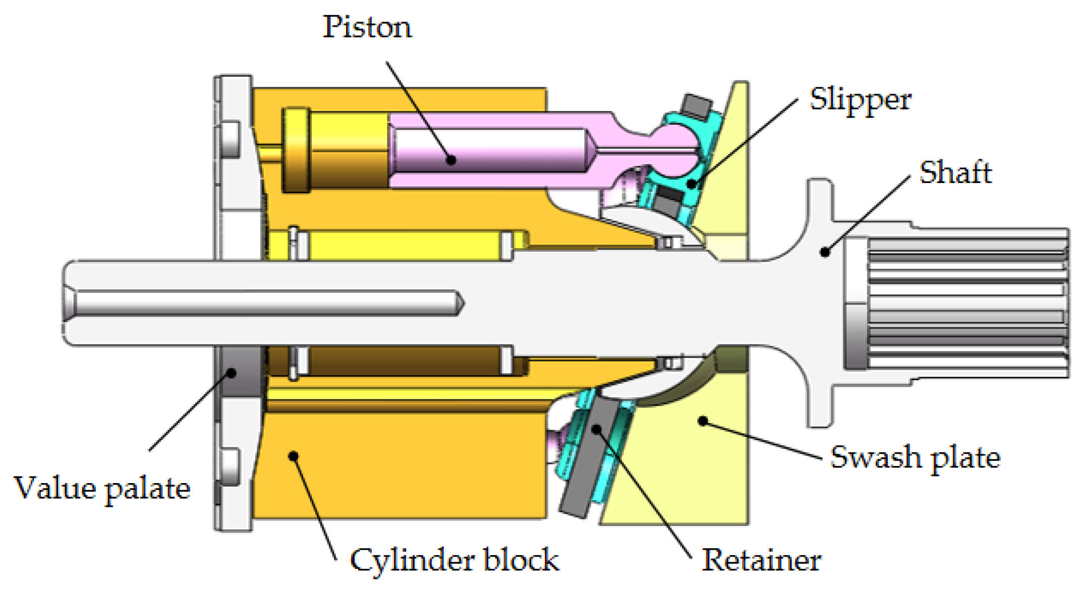
The swivel angle determines the displacement volume of the bent axis pump. The pistons in the cylinder bore moves when the shaft rotates. The swash plate, in the swash plate design, sustain the turning pistons. Moreover, the angle of the swash plate decides the piston stroke.
The bent axis principle, fixed or adjustable displacement, exist in two different designs. The first design is the Thoma-principle with maximum 25 degrees angle, designed by the German engineer Hans Thoma and patented in 1935. The second design goes under the name Wahlmark-principle, named after Gunnar Axel Wahlmark (patent 1960). The latter features spherical-shaped pistons in one piece with the piston rod and piston rings. And moreover a maximum 40 degrees between the driveshaft centre-line and pistons.
In general, the largest displacements are approximately one litre per revolution. However if necessary, a two-litre swept volume pump can be built. Often variable-displacement pumps are used, so that the oil flow can be adjusted carefully. These pumps generally operate with a working pressure of up to 350–420 bars in continuous work
Radial piston pumps are used especially for high pressure and relatively small flows. Pressures of up to 650 bar are normal. The plungers are connected to a floating ring. A control lever moves the floating ring horizontally by a control lever and thus causes an eccentricity in the centre of rotation of the plungers. The amount of eccentricity is controlled to vary the discharge. Moreover, shifting the eccentricity to the opposite side seamlessly reverses the suction and discharge.
Radial piston pumps are the only pumps that work continuously under high pressure for long periods of time. Examples of applications include: presses, machines for processing plastic and machine tools.
A vane pump uses the back and forth movement of rectangle-shaped vanes inside slots to move fluids. They are sometimes also referred to as sliding vane pumps.
The simplest vane pump consists of a circular rotor, rotating inside of a larger circular cavity. The centres of the two circles are offset, causing eccentricity. Vanes slide into and out of the rotor and seal on all edges. This creates vane chambers that do the pumping work.
A vacuum is generated when the vanes travel further than the suction port of the pump. This is how the oil is drawn into the pumping chamber. The oil travels through the ports and is then forced out of the discharge port of the pump. Direction of the oil flow may alter, dependent on the rotation of the pump. This is the case for many rotary pumps.
Vane pumps operate most efficiently with low viscosity oils, such as water and petrol. Higher viscosity fluids on the other hand, may cause issues for the vane’s rotation, preventing them from moving easily in the slots.
Gear pumps are one of the most common types of pumps for hydraulic fluid power applications. Here at Hydraulics Online, we offer a wide range of high-powered hydraulic gear pumps suitable for industrial, commercial and domestic use. We provide a reliable pump model, whatever the specifications of your hydraulic system. And we furthermore ensure that it operates as efficiently as possible.
Johannes Kepler invented the gear pump around year 1600. Fluid carried between the teeth of two meshing gears produces the flow. The pump housing and side plates, also called wear or pressure plates, enclose the chambers, which are formed between adjacent gear teeth. The pump suction creates a partial vacuum. Thereafter fluid flows in to fill the space and is carried around the discharge of the gears. Next the fluid is forced out as the teeth mesh (at the discharge end).
Some gear pumps are quite noisy. However, modern designs incorporating split gears, helical gear teeth and higher precision/quality tooth profiles are much quieter. On top of this, they can mesh and un-mesh more smoothly. Subsequently this reduces pressure ripples and related detrimental problems.
Catastrophic breakdowns are easier to prevent with hydraulic gear pumps. This is because the gears gradually wear down the housing and/or main bushings. Therefore reducing the volumetric efficiency of the pump gradually until it is all but useless. This often happens long before wear causes the unit to seize or break down.
Can hydraulic gear pumps be reversed? Yes, most pumps can be reversed by taking the pump apart and flipping the center section. This is why most gear pumps are symmetrical.
External gear pumps use two external spur gears. Internal gear pumps use an external and an internal spur gear. Moreover, the spur gear teeth face inwards for internal gear pumps. Gear pumps are positive displacement (or fixed displacement). In other words, they pump a constant amount of fluid for each revolution. Some gear pumps are interchangeable and function both as a motor and a pump.
The petrochemical industry uses gear pumps to move: diesel oil, pitch, lube oil, crude oil and other fluids. The chemical industry also uses them for materials such as: plastics, acids, sodium silicate, mixed chemicals and other media. Finally, these pumps are also used to transport: ink, paint, resins and adhesives and in the food industry.
Mathematical calculations are key to any type of hydraulic motor or pump design, but are especially interesting in the gerotor design. The inner rotor has N teeth, where N > 2. The outer rotor must have N + 1 teeth (= one more tooth than the inner rotor) in order for the design to work.

The pump model is represented by the subsystem named Axial-Piston Pump. The prime mover rotating the pump is simulated with the Ideal Angular Velocity source. The pump output passes through a pipeline, control unit, and a variable orifice that acts as a load. To test control unit response to variable load, the orifice changes its area during simulation. The change profile is implemented by the Spool Pos subsystem.
The control unit in the test rig is represented by the subsystem named Pressure/Flow Control Unit. The load-sensing function of the pump control uses a fixed orifice. The control unit keeps the pressure differential across this orifice constant, regardless of pump loading. The control unit receives signals on pump output pressure and load pressure, measured after the flow control valve. Based on these pressures, the unit produces yoke displacement, which affects the angular position of the angled swash plate in the pump. This helps maintain the specified pressure differential across the flow control valve and prevent pump pressure from exceeding the preset value.
Every piston of the pump is represented by a subsystem called Piston. These subsystems are identical and are connected to the following external ports of the pump model:
The suction ports of all pistons (ports A) are connected to the output of a low pressure booster pump, which is simulated with the Ideal Hydraulic Pressure Source block. The output pressure of the booster pump is set to 5e5 Pa.
The yoke is connected to the Y ports of all pistons, thus acting on the angled plate of the swash mechanism. The displacement of the yoke is limited by the hard stop.
The model of the piston (Figure 4) is based on the Single-Acting Hydraulic Cylinder block, which is mechanically connected to the drive shaft through the Swash Plate block. The cylinder is also hydraulically connected to ports A and B through the Porting Plate Variable Orifice blocks. Ports A and B represent pump discharge and intake ports, respectively.
The pistons are evenly spread along the pitch circle of the piston cylinder, as shown in Figure 2. This makes the angle between pistons 360/5 = 72 degrees.
Let us assume that the first piston (marked P1 in the schematic) is located exactly at the reference point that corresponds to the lowest piston position. Let us further assume that port A represents the intake outlet of the pump. In other words, the piston moving along slot A in positive direction (clockwise in this case) goes up, and its chamber is filled with fluid by a booster pump. This means that the Phase angle parameter of the Porting Plate Variable Orifice A in Piston 1 must be set to zero. The same parameter of the Porting Plate Variable Orifice B in Piston 1 must be set to 180 degrees, because it starts interacting with slot B (pump discharge port) only after rotation by 180 degrees.
In the piston model, parameters Phase angle of each Porting Plate Variable Orifice block are denoted as Phase angle A and Phase angle B, respectively. The values of the phase angle for all five pistons are computed in the initialization section of the Axial-Piston Pump subsystem mask editor. The following table shows their values in degrees, with the corresponding values in radians given in parenthesis:
The Swash Plate block in the piston model also requires phase angle to be assigned, to specify the position of a piston with respect to the inclined surface. With the selected reference point, the values of the swash plate phase angle coincide with the Phase angle A values, as shown in the table.
The Porting Plate Variable Orifice blocks require angular position of the respective piston at their input. This function is performed by the Angle Sensor block.
Other important parameters are the stroke of the cylinder and the initial position of the piston with respect to the cylinder cap. The stroke must be large enough to allow the piston to reciprocate even at the maximum angle of the swash plate
In the model, the maximum angle is set to 35 degrees (0.6109 rad) and pitch radius is set to 0.04 m, which makes the stroke to be greater than 0.056 m. The stroke is set 0.06 m. The piston initial positions must be equal to half of the stroke at zero initial swash plate angle. But the initial angle changes its value depending on the initial position of the actuator. As a result, the piston initial positions are computed with the equation
The purpose of the control unit is to implement two functions: load sensing and pressure limiting. The load sensing is implemented by maintaining specified pressure differential across the flow control valve. In the model of the test rig (Figure 1), the flow control valve is simulated with the Orifice with Variable Area Slot block. Pressures upstream and downstream of the valve are conveyed to the Pressure/Flow Control unit via ports P and LSP (Figure 5).
These pressures act on the side faces of the 3-way directional valve and shift the valve proportionally to the pressure difference and setting of the centering springs. The valve connections are selected in such a way that increased pressure differential opens path A-P and closes path A-T. The actuator is arranged as a single-rod differential hydraulic cylinder with rod connected to the pump yoke. The pump displacement is increased if the rod moves in the direction of the arrow shown in the schematic. Due to difference between cylinder effective areas, the displacement is increased if both cylinder chambers are connected to the pump, and decreased if the chamber without rod is connected to tank. As a result, increased pressure differential across the valve causes the pump to decrease its displacement until it returns to preset value. The spring preload of the valve is determined with the equation
The purpose of the pressure limiting function is to prevent pump pressure from exceeding the preset value. It is implemented with the pressure-relief valve and the orifice in the LSP line. The pressure-relief valve is set to the desired maximum value. When pump pressure builds up to this value, the valve opens and causes pressure in the right chamber of the valve to decrease opening path A-P. The actuator shifts to the right until the pressure returns to the preset value.
The model of a load-sensing valve is built using the 3-Way Directional Valve, Hydraulic Double-Acting Valve Actuator, Pressure-Relief Valve, and Fixed Orifice blocks, as shown in the model diagram (Figures 6 and 7).
The pressure differential is set to 20 bar. The 3-Way Directional Valve path A-T must be initially open, to force the pump to increase its displacement at the start of operation. To perform the load-sensing function, pressure increase at the B port (load-sensing port) must open the A-T path and close the A-P path. These are the reasons that determined the valve port connections to the system. The remaining load sensing control valve parameters, such as spring stiffness, valve stroke, valve orifice area, and so on, are tuned in the model to ensure required accuracy, stability, and numerical effectiveness.
The pressure-limiting function is implemented with the combination of the Fixed Orifice and Pressure-Relief Valve blocks. The valve is set to 250 bar. At this pressure, increased flow through the fixed orifice causes pressure at port Y of the Hydraulic Double-Acting Valve Actuator (block Valve Actuator in Figure 7) to drop, which eventually decreases the displacement of the pump.
The cycle starts with zero opening signal, followed by opening of 2.8, 5.2, 1, -0.8, and, finally, 2.45 mm. At the start of the cycle, the pump shaft starts rotating at 260 rad/s (~2500 RPM) with the pump yoke initial position set to 5 mm. The servo cylinder starts increasing pump displacement, pump pressure slowly builds up, and the process settles down at ~0.35 s after the pressure differential across the flow control valve becomes close to preset value of 20 bar. The load-sensing valve is opened at this moment by ~1.2 mm.
At 1 s, the load valve is practically fully closed, causing pump pressure to rise. The load-limiting function becomes dominant as the pressure reaches 270 bar. The pump returns to the load-sensing mode after the pressure falls below the preset value.
The plot below shows the flow rate within the pump pistons and at the load. The cyclic nature of the piston pressures can be seen, as well as the overall behavior of the pump which stays close to its rated flow rate.
The plots show the load sensing and pressure limiting control. The pump maintains its rated flow rate of 1.1 m^3/s even as the load changes, as shown on the pump output pressure plot. However, as the pump output pressure rises to its maximum rated pressure, the pressure limiting control adjusts the yoke position is and the flow rate drops below its rated flow rate.

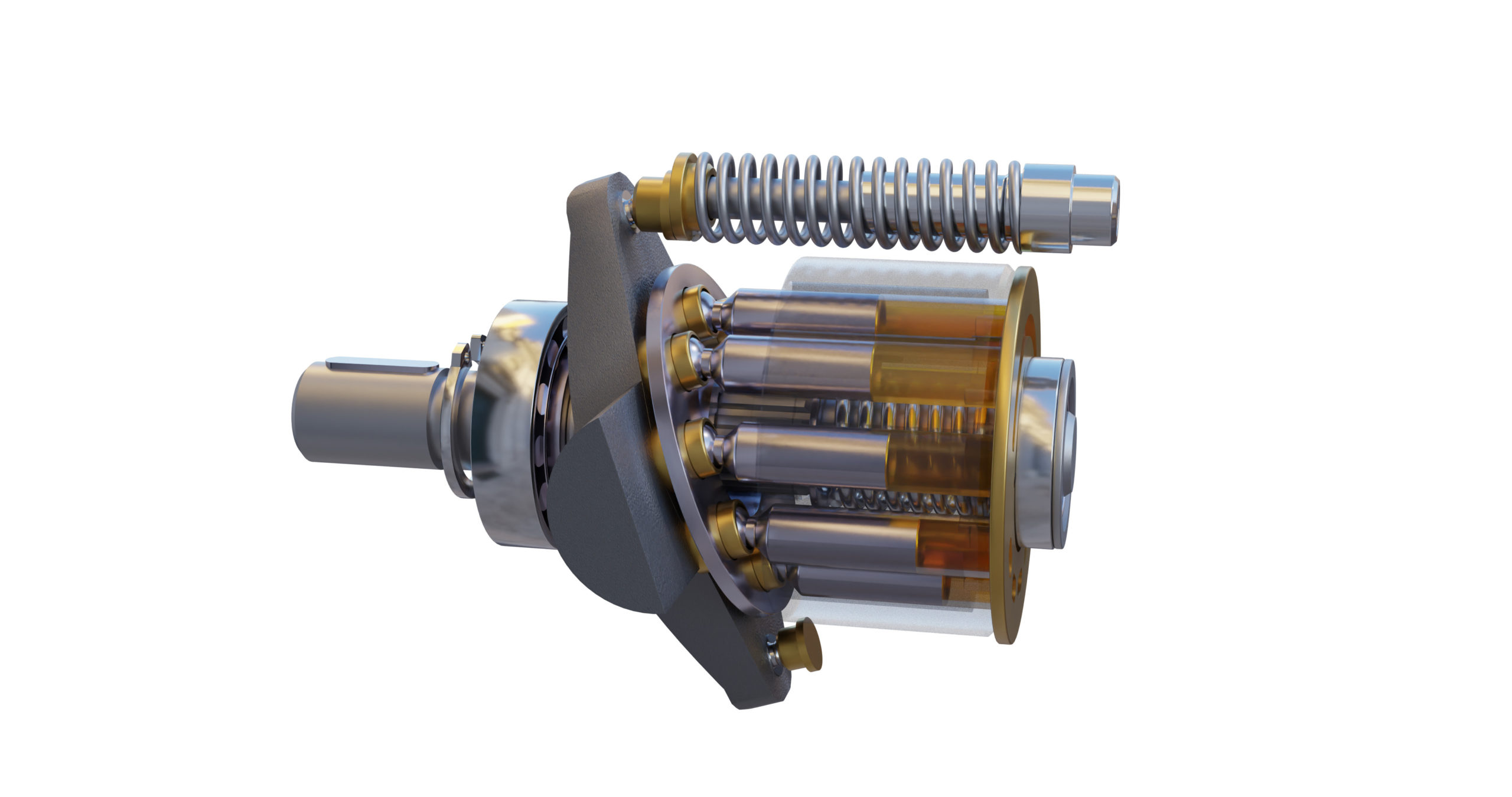
In an axial-piston pump, the pistons and cylinder rotate around the center, longitudinal axis. The pistons and shoes move in and out of the cylinder because they are sliding upon a stationary, variable angle, swashblock.
As the pistons rotate, they alternate between being connected to an inlet port and an outlet port. As the pistons pass over the inlet port, they suck fluid into the piston chamber. As they move over the outlet port, they expel fluid from the piston chamber.

The hydraulic piston pumps are the core power source of the hydraulic transmission system, which are the “heart” of the hydraulic system. The reliability of its work is the key to ensure the high precision, high speed, stable operation of many national defense equipment and industrial equipment. Once the piston pump breaks down, downtime will occur, and the entire production line maybe paralyzed. More severely, it could even cause a catastrophic accident [1,2]. However, hydraulic pumps often face rigorous operating conditions such as high temperature, heavy load, high speed, and high pressure, which accelerate the deterioration of the health condition of the hydraulic pumps [3,4]. Therefore, the investigation on the intelligent fault diagnosis of the piston pump plays a practical and significant role in safe and efficient production, personnel health, and so on [5,6].
In recent years, due to the reliance of traditional mechanical fault diagnosis on expert experience and knowledge, the diagnosis process consumes a lot of human resources, which is gradually unable to meet the needs of industrial production. Encouragingly, the rapid development of artificial intelligence has profoundly changed human social life and promoted the intelligentialize of traditional industries. Correspondingly, intelligent diagnosis methods have gradually become mainstream. On account of the excellent data processing capabilities, many methods based on artificial intelligence have gradually been employed in the territory of mechanical fault diagnosis, such as convolutional neural networks (CNN) [7,8,9], autoencoder [9,10], deep belief networks [11,12], and recurrent neural networks [13,14].
Aiming at the difficult operation and maintenance of complex engineering system for health diagnosis, Tamilselvan et al. applied deep learning to accomplish mechanical fault diagnosis [15]. A multi-sensor health diagnosis method was proposed on the basis of deep belief network, which was considered to be the landmark breakthrough for fault diagnosis combining deep learning model [15]. Moreover, Jiang et al. combined multi-sensor information fusion with support vector machine (SVM) to realize the fault diagnosis of gear and rolling bearing [16]. Azamfar et al. stacked different frequency domains data into two-dimensional matrix as the input of CNN to implement fault diagnosis of gearboxes, and the effect is more accurate than traditional machine learning methods [17]. Luwei et al. fused vibration data of different positions and combined with artificial neural network (ANN) to realize fault diagnosis of rotating machinery [18]. On the basis of coherent composite spectrum (CCS), Yunusa-Kaltungo et al. realized fault diagnosis of rotating machinery via combining multi-sensor data with ANN [19]. Liu et al. utilized cascade-correlation neural network to realize fault diagnosis of mechanical equipment, which indicates that the result of multi-data fusion is better than single data [20]. Wang et al. alleviated the conflict between multi-sensors data via improving the sensor, which has good application in the field of fault diagnosis [21]. Based on Elman ANN, Kolanowski et al. built a navigation system, which can easily add other sensors and make data better fusion [22]. In addition, intelligent fault diagnosis generally includes two portions, feature extraction and self-learning classification of neural network model respectively [23]. For the sake of surmounting the problem of over-fitting created by the small amount of data in hydraulic pumps, Kim et al. combined with deep learning models to achieve the status detection of hydraulic system. It was worth pointing out that sensors were used to collect signals and meanwhile joggling was performed to simulate additional noise to expand the amount of sample data [24]. Zhang et al. used continuous wavelet transform (CWT) to obtain single-channel time-frequency diagrams of bearing vibration signals and merged three single-channel samples into three-channel samples as input data. The fault diagnosis was realized by using multi-channel sample data and demonstrated to be better than that of single-channel sample data [25]. Quinde et al. combined Wigner–Ville distribution with local mean decomposition (LMD) to realize bearing fault diagnosis based on one-dimensional signals [26]. Zhao et al. proposed a normalized CNN that combined batch normalization (BN) with exponential moving average (EMA) technology to construct a fault diagnosis model. The established model can be suitable for data imbalance and changing working conditions and obtained the desirable fault diagnosis performance for rotating machinery [27]. In terms of the structure of networks, Che et al. built a deep residual network model to tackle the problems such as complex fault types and long vibration signal sequences. The residual module was added to the CNN to further reduce the training error of the model, and intelligent fault diagnosis of bearing was finally achieved [28]. Aiming at the difficulties of feature extraction and poor robustness of the model, Wei et al. combined CNN with long short-term memory (LSTM) to achieve fault diagnosis of piston pumps with different cavitation degrees. The model still presented good robustness in the case of additional noise [29]. Kumar et al. introduced a new divergence function into the cost function, thereby reducing the complexity of the hidden layers, and finally the accuracy of diagnosis of centrifugal pump component defects was raised by 3.2% [30]. Al-Tubi et al. used genetic algorithms to adjust hidden layers of support vector machines to achieve fault diagnosis of centrifugal pumps [31]. Siano et al. combined fast Fourier transform with an artificial neural network to achieve the online detection of pump cavitation [32]. For the fault diagnosis of the piston pump, Du et al. built an integrated model and obtained the higher accuracy than the models for contrastive analysis. The model combined the sensitivity analysis (SA) of the characteristic parameters with the empirical mode decomposition (EMD). The higher sensitivity characteristics were input into probabilistic neural networks (PNN) for feature learning. The model still had good generalization performance in the multi-mode recognition state [33]. Wang et al. used a band-pass filter to improve the performance of minimum deconvolution and effectively detect the bearing failure of the piston pump [34]. Lu et al. used sparse empirical wavelet transform to process vibration signals of gear pump, combined with adaptive dynamic least squares support vector machine method (LSSVM) to achieve gear pump fault diagnosis, and the effect was better than empirical wavelet transform combined with LSSVM [35]. Although the above studies have adopted deep learning models in mechanical fault diagnosis and have achieved many beneficial research results, however, they require high signal processing-related knowledge in feature extraction and consume vast range of human resources in data processing. More importantly, deep learning is rarely utilized in the fault diagnosis field of hydraulic piston pump. The advantages of the deep learning models in feature self-learning need to be further explored.
The vibration signal of the hydraulic piston pump is a typical non-stationary signal [1,36]. The short-time Fourier transform, Wigner transform, and wavelet transform are widely utilized in the analysis of non-stationary signals [37,38,39]. Short-time Fourier transform has a defect of low resolution [40]. Wigner transform has so-called “cross-term” interference that cannot be explained and suppressed to multi-component signals [41]. The wavelet transform inherits the localization idea of the short-time Fourier transform and makes up for the weakness that the size of the sliding window does not change with frequency. It has high resolution and can well extract the time domain and frequency domain characteristics of non-stationary signals. Therefore, wavelet transform gradually becomes an important method to deal with non-stationary signals. The results of wavelet transform are displayed in the form of RGB images, which is essentially the response of the energy intensity of the signal at different times and frequencies. It can show the detailed changes of the signal and describe the fault characteristics in the signal [42]. Therefore, it can be used to extract the fault characteristics of the vibration signal of the piston pump, which provides an auxiliary path for the fault diagnosis of piston pumps.
The constructed deep CNN simplifies the structure of the classic AlexNet network model. The classic AlexNet with five convolutional layers is reduced to the model with three convolutional layers. The full connected layer, convolutional layer and maxpooling layer are redesigned. The number of maxpooling kernel, convolutional kernel, and full connected layer neurons are adjusted. The LRN layer is removed on account of the minor influence on the diagnostic accuracy. The constructed deep CNN is trained based on dataset of real axial piston pump. Four optimizers are utilized in the gradient descent process of constructed CNN model, and the Adam optimizer is finally selected, which can make the model training process converge fastest, steady and improve generalization ability. Moreover, the hyperparameters are optimized for the enhance performance, including learning rate, batch size, the number and the size of convolutional kernel, and dropout rate. The quantity of convolution kernels are unified in each layer, and the quantity of nodes in the fully connected layer are improved. The RELU activation function is employed. The input data are three-channel feature images. The constructed deep CNN model is composed of three convolutional layers, three pooling layers, and three fully connected layers. Each pooling layer is connected behind each convolutional layer. The random inactivation neuron operation is added to the former two fully connected layers to avoid the overfitting of proposed model. The last layer is the softmax classifier for image classification. Compared with the classic AlexNet model, the structure is simplified, and the number of the parameters is enormously reduced in the improved CNN model. Moreover, the proposed model costs the shorter computation time and presents the higher classification performance compared with the other CNN models.
This article is composed as follows: in Section 2, the basic theory of CWT is briefly introduced. In Section 3, the principle of CNN is described, including the convolutional layer, pooling layer, and classification layer. In Section 4, the improvement of AlexNet model is described and analyzed. In Section 5, the proposed method is verified with measured fault data of hydraulic pump, and the test results are discussed. In Section 6, conclusions are drawn, and future research is prospected.
Hydraulic systems are in general members of the fluid power branch of power transmission. Hydraulic pumps are also members of the hydraulic power pack/hydraulic power unit family. Hydraulic units are encased mechanical systems that use liquids for hydraulics.
The hydraulic systems that hydraulic pumps support exist in a range of industries, among them agriculture, automotive manufacturing, defense contracting, excavation, and industrial manufacturing. Within these industries, machines and applications that rely on hydraulic pumps include airplane flaps, elevators, cranes, automotive lifts, shock absorbers, automotive brakes, garage jacks, off-highway equipment, log splitters, offshore equipment, hydraulic motors/hydraulic pump motors, and a wide range of other hydraulic equipment.
When designing hydraulic pumps, manufacturers have many options from which to choose in terms of material composition. Most commonly, they make the body of the pump–the gears, pistons, and hydraulic cylinders–from a durable metal material. This metal is one that that can hold up against the erosive and potentially corrosive properties of hydraulic fluids, as well as the wear that comes along with continual pumping. Metals like this include, among others, steel, stainless steel, and aluminum.
First, what are operating specifications of their customer? They must make sure that the pump they design matches customer requirements in terms of capabilities. These capabilities include maximum fluid flow, minimum and maximum operating pressure, horsepower, and operating speeds. Also, based on application specifications, some suppliers may choose to include discharge sensors or another means of monitoring the wellbeing of their hydraulic system.
Next, what is the nature of the space in which the pump will work? Based on the answer to this question, manufacturers will design the pump with a specific weight, rod extension capability, diameter, length, and power source.
Manufacturers must also find out what type of substance does the customer plan on running through the pumps. If the application calls for it, manufacturers can recommend operators add other substances to them in order to decrease the corrosive nature of certain hydraulic fluids. Examples of such fluids include esters, butanol, pump oils, glycols, water, or corrosive inhibitors. These substances differ in operating temperature, flash point, and viscosity, so they must be chosen with care.
All hydraulic pumps are composed in the same basic way. First, they have a reservoir, which is the section of the pump that houses stationary fluid. Next, they use hydraulic hoses or tubes to transfer this fluid into the hydraulic cylinder, which is the main body of the hydraulic system. Inside the cylinder, or cylinders, are two hydraulic valves and one or more pistons or gear systems. One valve is located at each end; they are called the intake check/inlet valve and the discharge check/outlet valve, respectively.
Hydraulic pumps operate under the principle of Pascal’s Law, which states the increase in pressure at one point of an enclosed liquid in equilibrium is equally transferred to all other points of said liquid.
To start, the check valve is closed, making it a normally closed (NC) valve. When the check is closed, fluid pressure builds. The piston forces the valves open and closes repeatedly at variable speeds, increasing pressure in the cylinder until it builds up enough to force the fluid through the discharge valve. In this way, the pump delivers sufficient force and energy to the attached equipment or machinery to move the target load.
When the fluid becomes pressurized enough, the piston withdraws long enough to allow the open check valve to create a vacuum that pulls in hydraulic fluid from the reservoir. From the reservoir, the pressurized fluid moves into the cylinder through the inlet. Inside the cylinder, the fluid picks up more force, which it carries over into the hydraulic system, where it is released through the outlet.
Piston pumps create positive displacement and build pressure using pistons. Piston pumps may be further divided into radial piston pumps and axial piston pumps.
Radial pumps are mostly used to power relatively small flows and very high-pressure applications. They use pistons arranged around a floating center shaft or ring, which can be moved by a control lever, causing eccentricity and the potential for both inward and outward movement.
Axial pumps, on the other hand, only allow linear motion. Despite this, they are very popular, being easier and less expensive to produce, as well as more compact in design.
Gear pumps, or hydraulic gear pumps, create pressure not with pistons but with the interlocking of gear teeth. When teeth are meshed together, fluid has to travel around the outside of the gears, where pressure builds.
External gear pumps facilitate flow by enlisting two identical gears that rotate against each other. As liquid flows in, it is trapped by the teeth and forced around them. It sits, stuck in the cavities between the teeth and the casing, until it is so pressurized by the meshing of the gears that it is forced to the outlet port.
Internal gear pumps, on the other hand, use bi-rotational gears. To begin the pressurizing process, gear pumps first pull in liquid via a suction port between the teeth of the exterior gear, called the rotor, and the teeth of the interior gear, called the idler. From here, liquid travels between the teeth, where they are divided within them. The teeth continue to rotate and mesh, both creating locked pockets of liquid and forming a seal between the suction port and the discharge port. Liquid is discharged and power is transported once the pump head is flooded. Internal gears are quite versatile, usable with a wide variety of fluids, not only including fuel oils and solvents, but also thick liquids like chocolate, asphalt, and adhesives.
Various other types of hydraulic pumps include rotary vane pumps, centrifugal pumps, electric hydraulic pumps, hydraulic clutch pumps, hydraulic plunger pumps, hydraulic water pumps, hydraulic ram pumps, portable 12V hydraulic pumps, hydraulic hand pumps, and air hydraulic pumps.
Rotary vane pumps are fairly high efficiency pumps, though they are not considered high pressure pumps. Vane pumps, which are a type of positive-displacement pump, apply constant but adjustable pressure.
Centrifugal pumps use hydrodynamic energy to move fluids. They feature a rotating axis, an impeller, and a casing or diffuser. Most often, operators use them for applications such as petroleum pumping, sewage, petrochemical pumping, and water turbine functioning.
Electric hydraulic pumps are hydraulic pumps powered by an electric motor. Usually, the hydraulic pump and motor work by turning mechanisms like impellers in order to create pressure differentials, which in turn generate fluid movement. Nearly any type of hydraulic pump can be run with electricity. Most often, operators use them with industrial machinery.
Hydraulic clutch pumps help users engage and disengage vehicle clutch systems. They do so by applying the right pressure for coupling or decoupling shafts in the clutch system. Coupled shafts allow drivers to accelerate, while decoupled shafts allow drivers to decelerate or shift gears.
Hydraulic ram pumps are a type of hydraulic pump designed to harness hydropower, or the power of water, to elevate it. Featuring only two moving hydraulic parts, hydraulic ram pumps require only the momentum of water to work. Operators use hydraulic ram pumps to move water in industries like manufacturing, waste management and sewage, engineering, plumbing, and agriculture. While hydraulic ram pumps return only about 10% of the water they receive, they are widely used in developing countries because they do not require fuel or electricity.
Hydraulic water pumps are any hydraulic pumps used to transfer water. Usually, hydraulic water pumps only require a little bit of energy in the beginning, as the movement and weight of water generate a large amount of usable pressure.
Air hydraulic pumps are hydraulic pumps powered by air compressors. In essence, these energy efficient pumps work by converting air pressure into hydraulic pressure.
Hydraulic pumps are useful for many reasons. First, they are simple. Simple machines are always an advantage because they are less likely to break and easier to repair if they do. Second, because fluid is easy to compress and so quick to create pressure force, hydraulic pumps are very efficient. Next, hydraulic pumps are compact, which means they are easy to fit into small and oddly shaped spaces. This is especially true in comparison to mechanical pumps and electrical pumps, which manufacturers cannot design so compactly. Speaking of design, another asset of hydraulic pumps is their customizability. Manufacturers can modify them easily. Likewise, hydraulic pumps are very versatile, not only because they are customizable, but also because they can work in places where other types of pump systems can’t, such as in the ocean. Furthermore, hydraulic pumps can produce far more power than similarly sized electrical pumps. Finally, these very durable hydraulic components are much less likely to explode than some other types of components.
To make sure that your hydraulic pumps stay useful for a long time, you need to treat them with care. Care includes checking them on a regular basis for problems like insufficient fluid pressure, leaks, and wear and tear. You can use diagnostic technology like discharge sensors to help you with detect failures and measure discharge pressure. Checking vibration signals alone is often not enough.
To keep yourself and your workers safe, you need to always take the proper precautions when operating or performing maintenance and repairs on your hydraulic pumps. For example, you should never make direct contact with hydraulic fluid. For one, the fluid made be corrosive and dangerous to your skin. For two, even if the pump isn’t active at that moment, the fluid can still be pressurized and may potentially harm you if something goes wrong. For more tips on hydraulic pump care and operation, talk to both your supplier and OSHA (Occupational Safety and Health Administration).
Pumps that meet operating standards are the foundation of safe and effective operations, no matter the application. Find out what operating standards your hydraulic pumps should meet by talking to your industry leaders.
The highest quality hydraulic pumps come from the highest quality hydraulic pump manufacturers. Finding the highest quality hydraulic pump manufacturers can be hard, which is why we have we listed out some of our favorites on this page. All of those whom we have listed come highly recommended with years of experience. Find their information nestled in between these information paragraphs.
Before checking out any of these suppliers, we recommend you take some time to jot down your specifications. That way, you will have an easier time figuring out which ones have potential for you and which ones do not. Plus, when you are ready to talk to a supplier, your list will help you steer the conversation. Do not forget to include in your list the nitty-gritty details like your timeline, your budget and your delivery preferences.
Once you have put together you list, get to browsing. Pick out three or four hydraulic pump supply companies to which you’d like to speak, then reach out to each of them. After you’ve spoken with representatives from each company, decide which one will best serve you, and get started on your project.

Hydraulic systems use pumps to push fluid from the reservoir through the system, converting mechanical energy into hydraulic fluid power. Certain valves help direct the flow of the fluid, others relieve pressure when needed.
Hydraulic systems are used in everything from construction and agricultural equipment, industrial machinery, trains, planes and automobiles. A hydraulic system performs significant work in many applications, such as:
The hydraulic reservoir holds the fluid and transfers heat from the system, causing unwanted contaminants to sink and forcing air and moisture to release from the fluid.
The pump in a hydraulic system converts mechanical energy into hydraulic energy by the movement of the fluid. There are three primary kinds of hydraulic pumps, including:
All of these styles are intended for specific applications, such as variable displacement vane pumps or bent-axis piston pumps. However, all hydraulic pumps work on the same principle: displacing fluid volume to an opposing load in order to create the necessary pressure to move the piston.
Hydraulic valves are used to start, direct or stop fluid flow in the system. The valves in a hydraulic system are actuated by hydraulic, pneumatic, manual, electrical or mechanical controls.
Hydraulic actuators convert hydraulic energy to mechanical energy. This is typically done via a hydraulic cylinder converting hydraulic energy into linear motion OR a hydraulic motor converting hydraulic energy into rotary motion.
The principle of a hydraulic system is based on Pascal’s Law, which asserts: If pressure is applied to fluid in a hose, tube or pipe, it will transmit a force acting on a small area and generate a proportionally bigger force on a larger area/device, such as a piston within a cylinder. The piston rod moves due to the force of the pressure acting upon a cylinder, which will push, pull, press or lift something that requires exceptional force.
A very small hydraulic cylinder can create a large amount of force, especially when compared to electrical components. An alternative electrical system would necessitate a comparatively large* electric motor, requiring much more power to provide the same amount of force as a hydraulic system.

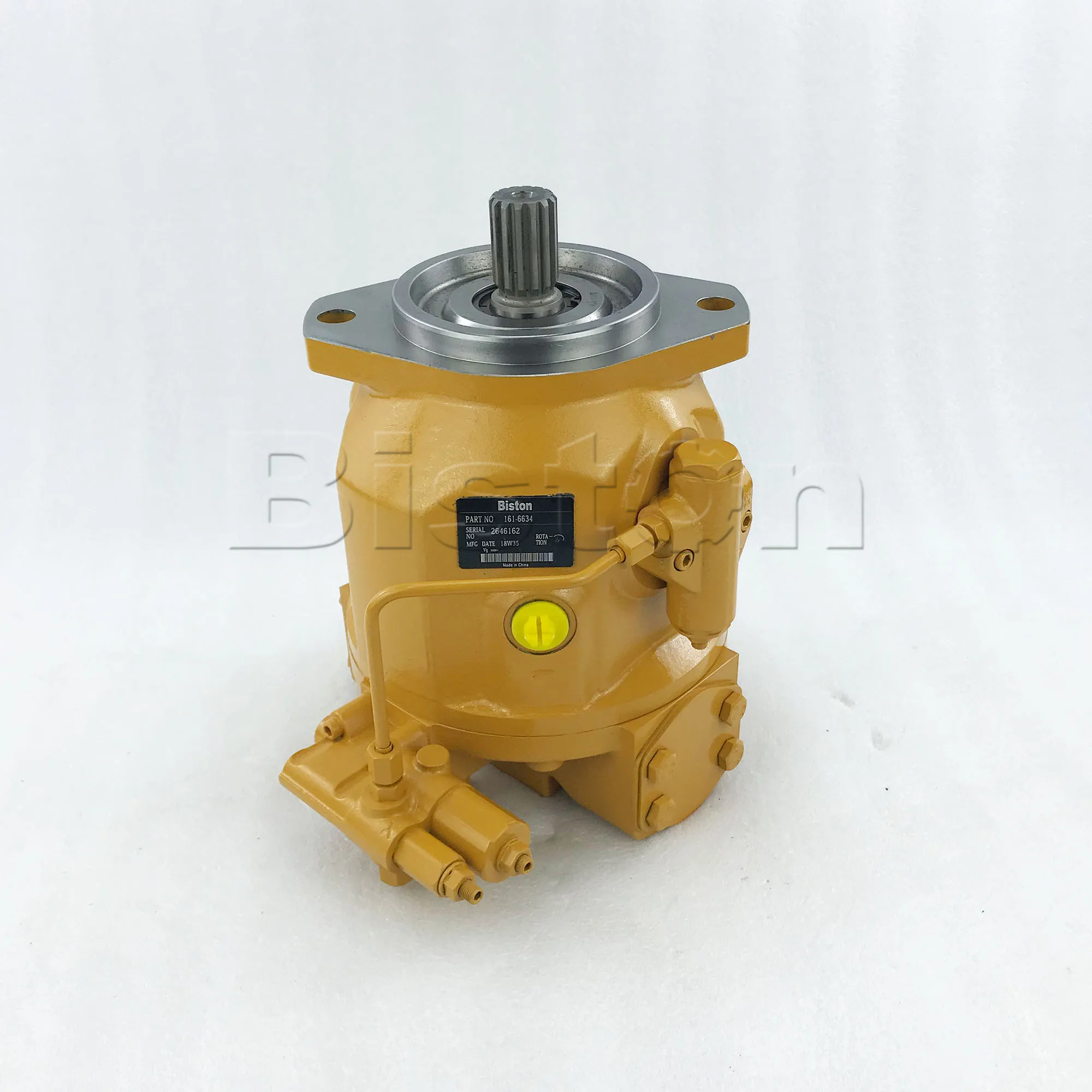
The hydraulic axial piston pump Made in China is a new design, through excellent processing technology and high-quality raw materials, the performance of hydraulic axial piston pump Made in China up to a higher standard. We are perfect for every detail of the hydraulic axial piston pump Made in China, guarantee the quality level, so as to bring you the perfect product experience. Jinan Fucheng Hydraulic Equipment Co., Ltd. is a professional China hydraulic axial piston pump Made in China manufacturer and supplier, if you are looking for the best hydraulic axial piston pump Made in China with low price, consult us now!
The working environment of seawater axial piston hydraulic pump is harsh, and it is difficult to diagnose due to insufficient fault database. In contrast, pumps of the same type but using hydraulic oil have an adequate fault database and are easy to diagnose. In view of the above situation, a fault diagnosis method of seawater hydraulic piston pump based on transfer learning is proposed. The method decomposes the original sampled fault signal by complementary ensemble empirical mode decomposition (CEEMD) to obtain the intrinsic mode function (IMF) that can characterize the original signal. The singular value decomposition (SVD) is performed on the IMF. Then, the obtained singular value is used as a feature parameter to construct a feature vector. The feature data of seawater hydraulic pump and oil pump are used as target data and auxiliary data to form training data. The training data is trained based on the iterative adjustment of the weight through the TrAdaBoost transfer learning algorithm. Finally, the results of diagnosis and classification are compared with traditional machine learning. When the number of training data is 5 groups, the accuracy of transfer learning is 30.5% higher than that of traditional machine learning. The results show that transfer learning has great advantages in the case of a small number of samples.
The seawater axial piston hydraulic pump is an important component of the deep-sea application. The normal operation of the seawater axial piston hydraulic pump is the core component of the hydraulic system for deep sea applications. Seawater hydraulic system requires a healthy operation of the seawater hydraulic pump. Zhai et al. [1] simulated the cavitation flow of the seawater hydraulic axial piston pump based on the Schnerr–Sauer model, and analyzed the fluctuations of the pump outlet flow and pressure under different inlet pressure conditions. Dong et al. [2] studied corrosion and wear in seawater hydraulic pumps and introduced a new type of seawater hydraulic piston pump with better suction characteristics. Nie [3] analyzed and summarized the current status of seawater hydraulic piston pumps [4]. The research progress of port valve distribution and port plate distribution is analyzed. Alobaidi [5] analyzed various levels of cavitation in different operation conditions. A detailed analysis of the results obtained from the acoustic signal was carried out to predict cavitation in the pump under different operating conditions. Alobaidi [6, 7] also used vibration to detect, diagnosed the cavitation phenomenon in centrifugal pumps, and analyzed the vibration signal results obtained in the time and frequency domains in order to better understand the detection of cavitation phenomenon in the pumps.
Hydraulic pump is a mechanical system, and its diagnosis is usually monitored by measuring vibration or noise signals. Empirical mode decomposition (EMD) is a signal decomposition method proposed by Huang et al. [8], which can adaptively decompose the signal to obtain a series of high-to-low intrinsic mode function (IMF). This method is widely used in signal processing. Wu et al. [9] proposed the ensemble empirical mode decomposition (EEMD) by using the statistical properties of Gaussian white noise uniform distribution. However, this method cannot completely neutralize the artificially added white noise, which will lead to misjudgment of fault diagnosis. The complementary ensemble empirical mode decomposition (CEEMD) reduces the residual white noise in the EEMD reconstructed signal by adding positive and negative pairs of Gaussian white noise to the original signal [10, 11].
Machine learning is a hot topic in today"s scientific research, and it is also widely used in the field of fault diagnosis. Kankar [12] used Artificial Neural Network (ANN) and Support Vector Machine (SVM) to diagnose ball bearings [13–16] and conducted comparative experiments on the effectiveness of ANN and SVM. Shi et al. [17] proposed an early fault diagnosis method for manufacturing systems based on machine learning. The method of inductive learning is adopted to automatically obtain the statistical boundary vectors of the signal, and then a normal feature space is established, according to which an abnormal signal can be detected so that the faults in the complex system can be easily found. Alobaidi [18] extracted features from vibration signals that are used as inputs to the neural network. The method provided an intelligent system to be used in condition monitoring of centrifugal pumps. Huang et al. [19] proposed a new method for fault diagnosis hydraulic servo valve based on genetic algorithm for backpropagation neural network. Compared with other artificial neural networks, this method shortens the training time and improves the accuracy. However, the traditional machine learning method requires that the distribution of training data should be identical and sufficient [20], but seawater hydraulic pump is rarely used in engineering, and the fault data is relatively insufficient. Using seawater hydraulic pump fault data as training data is no longer suitable for traditional machine learning methods. Transfer learning is not limited to learning methods in which training data and test data have the same feature distribution. Transfer learning can learn to use the laws of knowledge in existing data to solve different but related fields, thereby effectively solving the problem of traditional machine learning.
In this paper, a fault diagnosis method for seawater axial piston hydraulic pump based on transfer learning is proposed. Section 1 introduces the signal processing method. Section 2 describes the research of transfer learning and transfer learning algorithm. Section 3 introduces the entire diagnosis process. Section 4 is to test and diagnose the fault, and diagnosis results are compared with the traditional machine learning method. This paper focuses on the application of transfer learning in fault diagnosis and proves that the transfer learning has higher diagnosis accuracy than the traditional machine learning algorithm in the case of few samples.
As shown in Figure 1, the complementary ensemble empirical mode decomposition (CEEMD) is used to decompose and select the original fault signal, and IMF representing the original signal is obtained. Singular value decomposition (SVD) is applied to IMF. Then, the singular value obtained by decomposition is used as the characteristic parameter. The characteristic data of seawater hydraulic pump and oil pump are used as target data and auxiliary data for training. The training data is trained by TrAdaBoost transfer learning algorithm based on iterative adjustment of weights.
The basic principle of CEEMD is essentially an improved algorithm based on EEMD. The decomposition process has three main steps [21–24]:(a)Add a pair of random Gaussian white noises in the signal :(b)The EMD algorithm is used to decompose and to obtain and , and the average value of each group of is calculated. The result is as follows:(c)Each component calculated in step (b) is recorded as . The signal is decomposed using the CEEMD and the result is as follows:where is the residual.2.1.2. Analysis of Correlation
Due to the influence of background noise and the insufficiency of the algorithm, the obtained by CEEMD decomposition has false components and noise components. The correlation coefficient is used to select the intrinsic mode function close to the original signal. The mathematical expression is [25]where is the covariance of , , , and is the standard deviation of and .
Singular value decomposition (SVD) is widely used in signal processing and fault diagnosis [26–28]. The singular value obtained by decomposition has stability invariance and can describe the intrinsic characteristics of the original signal. Orthogonal transformation is the essence of singular value decomposition (SVD). SVD is the generalization of spectrum analysis theory in the arbitrary matrix. The singular value of matrix is the inherent feature of matrix. It has very good stability. This way, the characteristic information of the hydraulic pump failure can be effectively extracted. The specific process of singular value decomposition is as follows.
For the matrix , the singular value decomposition form iswhere and are standard orthogonal matrices and is a diagonal matrix:where r is the rank of , and the singular value vector is
The phenomenon of transfer learning exists in various fields of real life. Many simple examples of daily life can also explain the rationale of transfer. For example, people who learn to ride bicycles can easily learn to ride motorcycles. People who learn English are more likely to learn Spanish. The basic idea of transfer learning is to learn the basic knowledge within a known source domain (auxiliary domain) and apply the learned knowledge to different but related unknown domains (target domains) to solve similar problems [29–32].
As shown in the following figures, different learning methods between the traditional machine learning method and the transfer learning method are, respectively, indicated. For a number of different learning tasks, the traditional machine learning method is to learn each task individually, and there is no correlation between the learning task processes; however, in the transfer learning process, a certain algorithm is used to learn knowledge from the relevant source fields and then solve the tasks or problems that exist in the target area. The difference between the two different machine learning methods can be clearly seen from Figure 2.
The TrAdaBoost transfer learning algorithm [33] is a machine learning algorithm based on iterative adjustment of weights. The learning process of the transfer learning algorithm TrAdaBoost is as follows.
The auxiliary data and the target data constitute a training sample. First, the data weight vector in the training sample is initialized (the first generation weight vector is the set):where is the number of auxiliary data and is the number of target data.
Based on the combined training dataset and its weight distribution and test dataset, a classifier on the test dataset is obtained and the error rate on the target data is calculated:where is the label of the sample data.
It can be seen that, in each iteration of the round if an auxiliary training data is misclassified, the weight of the data can be reduced. Specifically, the data is multiplied by , where the value is between 0 and 1. Therefore, in the next iteration, the misclassified sample will have less impact on the classification model than the previous round. After the iteration, the data in the auxiliary data that meets the target data will have a higher weight, and the weight of the auxiliary data that does not meet the target data will gradually decrease. Finally, the classification model is obtained.
In order to verify the effectiveness of the method proposed in this paper, the experimental platform of oil hydraulic and seawater hydraulic piston pump is built. The experimental schematic diagram is shown in Figure 3. The piston pump is driven by 45 KW variable frequency AC motor. The rated pressure of the pump is 21 MPa and the rated speed is 4000 r/m. Therefore, the corresponding shaft frequency is 6.7 Hz. In order to monitor the comprehensive health status of the pump, vibration sensor, pressure sensor, and flow sensor are installed on the piston pump assembly. The model of vibration sensor is ULT2059, the measuring range is 500 g, and the accuracy is 50 mV/g. The pressure sensor model is MPM480, and the range is (0–30)/(0–1) MPa. The model of flow sensor is CLG-15, and the range is (0–5)/(4.2–120) L/min. All sensors have 24 V DC power supply.
Experimental schematic diagram. (1) Seawater axial piston hydraulic pump. (2) Filter. (3) Throttle valve. (4) Safety valve. (5) Vibration sensor. (6) Pressure sensor. (7) Switch valve. (8) Flow sensor.
The vibration sensor is used to measure the radial vibration signal of the piston pump. The measurement error of acceleration sensor is 2.5 g. The radial vibration sensor is installed near the swash plate trunnion of the plunger pump, and the sampling frequency of the sensor is 2 KHz. The pressure sensor is used to measure the pressure signal at the inlet and outlet of the piston pump. LabWindows/CVI + RTX is used to edit the interactive interface of the host computer, and the latter is used to realize the communication between the software and the sensor and complete the analog to digital (A/D) conversion of the sensor input signal.
Taking a group of bearing fault data in the oil hydraulic pump data as an example, the CEEMD is used to decompose the sampling signal to obtain nine IMF and calculate the correlation coefficient between each IMF and the original signal. As shown in Table 1, the top 6 IMF of the 9 IMF had large correlation with the original signal, so they are selected as the data for use. As shown in Figure 4, the top 6 IMF components are selected.
The top 6 IMF components are selected, and SVD decomposition is performed on the IMF to calculate the singular values of sample data as a group of training data:
All the sample data are decomposed by CEEMD and SVD to form the training dataset. The data of seawater hydraulic pump is the target data, and the data of oil hydraulic pump is used as auxiliary data. In order to compare the two learning methods, the experimental data and feature extraction methods are unchanged, and the transfer learning algorithm is compared with the traditional machine learning algorithm. The auxiliary data is set to 100 groups. When the two learning modes have different sets of target data, the final fault diagnosis accuracy rate is compared.
It can be seen from Figure 5 that, in the case of a small amount of target data, the accuracy of conventional machine learning cannot be performed or the fault diagnosis is very low, and the transfer learning has a higher accuracy rate in this case. The smaller the number of target data, the more obvious the advantages of transfer learning. When the number of target data is 5 groups, the accuracy of transfer learning is 30.5% higher than that of SVM. The reason is that the classifiers trained by traditional machine learning are not accurate. However, transfer learning not only uses the target number data for training but also uses the data in the auxiliary data similar to the target data for training, which can train a better classifier.
As the number of target data increases, the diagnostic accuracy rate of transfer learning and traditional machine learning will also increase. The accuracy of traditional machine learning and transfer learning is the same when the number of target data increases to 25 groups. When the number of target data continues to increase, the diagnostic accuracy of traditional machine learning is slightly higher than that of transfer learning. When the amount of target data is large enough, both learning methods can achieve good performance. The reason for the above phenomenon is that when the number of target data increases, the amount of training data of the conventional machine learning increases and the accuracy of the trained classifier increases. With the increase of the amount of target data of transfer learning, the TrAdaBoost algorithm can filter out more auxiliary data similar to the target data to train a higher precision classifier. When the amount of target data increases to a certain amount, the traditional machine learning has enough training data to train high-precision classifiers. However, during the transfer learning process, the small amount of noise data included in the auxiliary data in the training set will have a little influence on the accuracy of the trained classifier. Therefore, when the target data volume is sufficient, the diagnostic accuracy rate of the traditional machine learning is better than that of the transfer learning.
A fault diagnosis method for seawater hydraulic pump based on transfer learning is proposed. The method uses CEEMD and SVD for data feature extraction. The feature data of seawater hydraulic pump and oil pump are used as target data and auxiliary data to form training data. In the iterative learning process of transfer learning, valuable and important sample weights are increased from generation to generation, but the weights of the secondary sample are reduced from generation to generation. Finally, compared with SVM, the results of transfer learning still have a high accuracy rate in the case of few target training data. The method solves the limitation that the traditional machine learning is not applicable under the condition that the training data and the test data do not have the same feature, and target training data is few. The fault diagnosis method based on transfer learning will also be applicable to the fault diagnosis of bearings or gears under variable working conditions.
The experimental data used to support the findings of this study were supplied by the research group of Key Laboratory of Advanced Manufacturing Technology under license and so we cannot put it into the system, and the requests for access to these data should be made to the corresponding author.
The authors would like to appreciate the support of National Natural Science Foundation of China (51605009, 51975011, and 51705026) and Fundamental Research Funds for the Central Universities (2019PTB-007).

This website is using a security service to protect itself from online attacks. The action you just performed triggered the security solution. There are several actions that could trigger this block including submitting a certain word or phrase, a SQL command or malformed data.


 8613371530291