
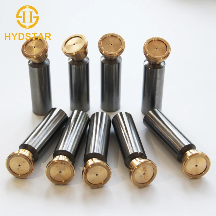
piston shoe hydraulic pump free sample
Our firm promises all users on the first-class products and solutions along with the most satisfying post-sale assistance. We warmly welcome our regular and new buyers to join us for Free sample for China “Germany Rexroth A4vg Plunger Variable Displacement Piston Pump A4vg180ep4dt2/32r-NZD02f011dp, We adhere for the tenet of “Services of Standardization, to meet Customers’ Demands”.
Our firm promises all users on the first-class products and solutions along with the most satisfying post-sale assistance. We warmly welcome our regular and new buyers to join us for China Hydraulic Pump, Hydraulic Motor, If any product meed your demand, remember to feel free to contact us. We’re sure your any inquiry or requirement will get prompt attention, high-quality solutions, preferential prices and cheap freight. Sincerely welcome friends all over the world to call or come to visit, to discuss cooperation for a better future!
8. It can be widely used in industry, such as plastic machine, shoe machine, die casting machinery and forklift and other industries hydraulic system, especially for servo variable frequency drive energy saving system.
This invention relates to a fluid pressure energy translating device and more particularly to an improved high pressure hydraulic axial piston pump or motor.
Such axial piston pumps or motors generally comprise an annular block or barrel defining a plurality of cylinders arranged concentrically of the barrel axis which each slidably receives one of a like plurality of pistons. The pistons are operatively connected through spherical bearings disposed with shoes to an inclined wobble plate or cam plate disposed adjacent one end of the barrel. The shoes slide on the stationary cam plate as the barrel is rotated. Reciprocation of the pistons in response to relative rotation between the cam plate and the barrel is thus effected. The barrel is supported on a drive shaft for rotation about its axis and about a fixed valve or port plate which engages the end of the barrel opposite the cam plate. The port plate has a pair of ports or passages for connection, respectively, to a source of fluid and to a discharge line. The ports in the port plate register with a plurality of spaced-apart ports in the barrel face which communicate with the individual cylinders so that fluid will be alternately introduced into and discharged from each cylinder as the barrel is rotated and the pistons reciprocate.
This problem is both significant and difficult to solve since not only is it dynamic, i.e., dependent upon speed and other operating conditions but it is also the result of several forces acting upon the barrel. Fluid pressurization and pumping by the pistons is accomplished by interaction between the cam plate and piston shoes. The force which the cam plate exerts on each of the piston shoes to pump fluid is balanced by a reaction force in the opposite direction. Due to the inclination of the cam plate, this axial reaction force produces a radial component of force tending to move the piston shoes radially away from the barrel axis and the cam plate. The forces from each of the piston shoes may be resolved into a single resultant force acting on the barrel and extending radially from the barrel axis at the point of intersection of the barrel axis and the plane of loci of the centers of the spherical bearings. It should be noted that the magnitude of this force is proportional to the hydraulic fluid pressure. It is thus not only dynamic but also independent of the rotational speed of the barrel.
A second force tending to tilt the barrel results from centrifugal force. The centers of gravity of some of the different pistons located around the barrel are axially offset from the diametrically opposed pistons. The centrifugal force on each piston acts through the center of gravity of the piston in a direction radially of the barrel. Since the centers of gravity of some of the pistons are axially offset from others, an unbalanced centrifugal force is applied to the barrel. The centrifugal force on diametrically opposed offset pistons applies a dynamic couple to the barrel which is the product of the centrifugal force acting on one of the pistons times the axial offset of the centers of gravity of the pistons. The magnitude of this couple will vary from zero in the case of opposed pistons in which the centers of gravity are aligned at right angles to the shaft to a maximum value in the case of opposed pistons in their maximum offset position. The magnitude of the couple is also directly related to speed.
A general solution to these problems which has been incorporated into the design of most contemporary axial piston pumps comprehends restraining either the barrel or port plate while permitting the other a certain amount of orientation freedom. Through this approach, barrel-valve plate misalignment which might result in leakage and blow-off is minimized since tilting or skewing of one of the elements may be accommodated by movement of the other. Another approach is disclosed in my prior U.S. Pat. No. 3,126,835. By supporting the barrel on a bearing on a drive shaft extending coaxially through the barrel and by properly locating the bearing, the effects of the dynamic couple formed from centrifugal force may be offset at least in part by the effects of the resultant force from fluid pressure acting on the pistons.
The unequal forces acting on the barrel also tend to slightly deflect the drive shaft which supports the barrel. If the barrel is rigidly connected to the drive shaft and the drive shaft deflects or bends slightly under loading, the barrel will tilt relative to the port plate and a loss of fluid pressure will occur. In my prior U.S. Pat. Nos. 3,126,835 and 3,160,109, a loss of fluid pressure resulting from deflection or bending of the drive shaft is reduced through the use of a torque tube interconnecting the drive shaft with the barrel and through the use of a crowned bearing between the drive shaft and the barrel. The torque tube extends coaxially along the drive shaft between the drive shaft and the barrel and has one end connected through splines to the drive shaft and an opposite end connected through splines to the barrel. As the shaft is driven, the torque tube in turn drives the barrel. The splines between the drive shaft and the torque tube and between the torque tube and the barrel also may be crowned to allow the shaft to flex relative to the barrel without tilting the barrel, as taught in my U.S. Pat. No. 4,232,587. As the drive shaft flexes under loading, the barrel is permitted to slide on the port plate without tilting away from the port plate. This construction has been effective in greatly reducing or eliminating tilting of the barrel and the resulting hydraulic fluid leakage.
In recent years, hydraulic component applications in various industries have become increasingly taxing. For example, axial piston pumps and motors are being asked to far exceed their design capabilities. Increases in both hydraulic pressure and rotational speeds are causing much higher rates of failure in axial piston pumps and motors. Failures primarily occur in the form of barrel-valve plate separation resulting in a loss in pressure of "blow-off" and loss of shoe contact with the surface of the cam plate.
Early axial piston pumps provided a direct drive between the drive shaft and the barrel. In one early design shown in U.S. Pat No. 2,642,810, the drive shaft was connected directly to the barrel through a splined connection having crowned or curved male splines on the drive shaft engaging straight splines on the barrel. As a consequence of the crowned splines, flexing of the drive shaft would not automatically tilt the barrel away from the port plate. However, since no bearing surface was provided between the drive shaft and the barrel, the direction of the tilting forces on the barrel due to centrifugal force and the direction of the tilting forces on the barrel due to fluid pressure acting on the pistons was cumulative, rather than subtractive as in the pumps shown in my above-described U.S. Pat. No. 3,126,835. Consequently, there was still a great tendency for barrel tilting relative to the port plate to occur in the pump shown in the U.S. Pat. No. 2,642,810 under high fluid pressure and high operating speed conditions. Another pump design shown in U.S. Pat. No. 2,915,985 provides both a straight spline connection and a spherical bearing connection between the drive shaft and the cylinder barrel. However, the straight spline connection prevents bending of the drive shaft relative to the barrel so that any flexing of the drive shaft under load is transferred through the splines to the barrel to cause the barrel to tilt away from the port plate.
According to the present invention, an improved axial piston hydraulic device is provided for operation either as a pump or a motor. The pump or motor provides a direct spline connection between a drive shaft and the barrel, allowing the pump to be adapted to higher operating speeds and loads. A bearing surface between the drive shaft and the barrel is also provided. According to the present invention, both the bearing and the male splines on the drive shaft are slightly crowned in the direction of the drive shaft axis. The drive shaft is designed such that when it flexes or bends under loading, the center of bending or curvature is located between the centers of the crowned spline and the crowned bearing. Furthermore, the crowned bearing is located on the drive shaft such that a plane defined by the loci of centers of the spherical connections between the pistons and the shoes which slide on the cam plate intersects the drive shaft axis at a point located between the center of the crowned bearing and the center of the crowned spline. Consequently, the resultant force acting upon the barrel to tilt the barrel caused by the fluid pressure exerted between the pistons and cam acts in an opposite direction from the couple produced by centrifugal forces acting upon the axially displaced opposing pistons. Although forces on the barrel cause flexing of the drive shaft under high operating speeds and loads, the locations of the centers of the crowned bearing and the crowned spline on opposite sides of the center of shaft bending allow the barrel to slide on the port plate rather than to tilt away from the port plate and cause a loss in fluid pressure.
Another object of the invention is to provide an axial piston hydraulic device capable of operating at relatively high speeds under high fluid pressures without the loss of fluid pressure due to tilting of the cylinder barrel.
Referring now to the drawings and particularly to FIGS. 1 and 2, a high pressure axial piston hydraulic pump 10 is illustrated in accordance with the preferred embodiment of the invention. It should be understood that the pump 10 is a fluid energy translating device which may be operated as either a pump or a motor. The pump 10 is capable of high pressure continuous duty operation and, for example, may be operated at pressures on the order of 5,000 psi or more for extended periods of time.
The pump 10 includes a tubular or annular housing body 11 having one end closed by a port cap 12 and an opposite end closed by a flange mount or base 13. A drive shaft 14 extends through the base 13 into the housing body 11. A radial thrust bearing 15 supports the drive shaft within the base 13 and a bearing 16 supports an end 17 of the drive shaft 14 within the port cap 12.
The barrel 19 defines a plurality of cylinders 23 which are uniformly spaced from the axis 18 and also are uniformly spaced circumferentially about the barrel 19. Each cylinder is connected through an independent passage 24 to an end surface 25 of the barrel 19. The barrel end surface 25 abuts a surface 26 on a valve or port plate 27. The port plate 27 is positioned between the barrel 19 and the port cap 12 and is indexed to the port cap 12 with a pin 28. The barrel 19 also defines a central cavity 29 having an annular groove 30 disposed generally adjacent the end surface 25. A snap ring 31 is seated in the annular groove 30 and provides axial restraint for one end of a compression spring 32. The other end of the compression spring 32 engages a shoulder 33 on the shaft 14. Since the shaft 14 is axially restrained by the radial thrust bearing 15, the compression spring 32 exerts a force on the barrel 19 to bias the barrel 19 against the port plate 27. During startup and during zero pressure operation, a fluid tight seal between the stationary port plate 27 and the rotating barrel 19 is maintained by the spring force exerted on the barrel 19 by the compression spring 32. Under load, hydraulic pressure maintains the barrel 19 against the port plate 27.
Each of the cylinders 23 within the barrel 19 is partially lined with a sleeve 40 fabricated of suitable bearing material. A piston 41 is slidably disposed within each cylinder sleeve 40. Each piston 41 has a ball or spherical end 42 which rotates within a corresponding socket in a shoe 43. The shoes 43 ride on a cam plate 44 which is disposed at a fixed angle relative to the axis 18 within a stationary support 45. The cam plate 44 is free to rotate within the stationary support 45. Operated as a pump, the shaft 14 rotates the barrel 19 and the shoes 43 ride on the cam plate 44 to reciprocate the pistons 41 within the cylinder sleeves 40. The stationary support 45 and fixed angle of the cam plate 44 provide a fixed displacement for the pump 10. It will be appreciated that the cam plate 44 may be adjustably supported in order to provide a variable displacement for the pump 10, as is illustrated, for example, in my prior U.S. Pat. No. 3,126,835 and in other prior art.
Details of the shoes 43 are shown in FIGS. 2 and 3. Each shoe 43 has an outer annular tilt land 46 and an inwardly spaced annular balance land 47 which ride on a flat surface 48 on the cam plate 44. A plurality of radial slots 49 extend through the tilt land 46, and may, for example, be spaced 90° apart about the tilt land 46. An annular oil groove 50 is located between the two annular lands 46 and 47.
A central region 51 interior of the balance land 47 is spaced from the cam plate surface 48. In the center of the central region 51, an oil passage 52 is located for communicating with an oil passage 53 within the piston 41 connected to the shoe 43. During the pressure stroke of the connected piston 41, a small amount of the hydraulic fluid being pumped is forced through a hollow center 54 in the connected piston 41, the piston passage 53, the shoe passage 52 to the central region 51 is between the shoe 43 and the cam plate 44. From the central region 51, a small amount of the hydraulic fluid flows between the balance land 47 on the shoe 43 and the cam plate surface 48 and then through the oil groove 50 and out the grooves 49 in the tilt land 46. The limited oil flow provides pressure balance of the forces on the shoes 43 and also produces a hydrostatic bearing between the cam plate surface 48 and the shoes 43 which permits them to readily slide over the cam plate surface 48 while under load.
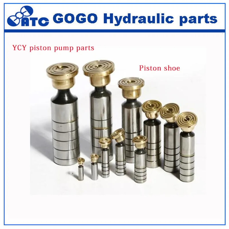
The outer surface of each shoe 43 is provided with a step 55 which is engaged by an annular retainer 56 which is parallel to the surface 48. The spacing between the retainer 56 and the cam plate surface 48 is only slightly greater than the thickness of the steps 55 on the shoes 43 so that the shoes 43 are free to rotate and slide on the cam plate 44 but are held in close contact with the cam plate 44. In prior art axial piston pumps, the shoes were generally formed from a bearing material, such as bronze. In the pump 10, the shoes 43 are formed from steel and have a layer of bronze bonded to the lower surface for forming at least the surface portions of the lands 46 and 47 which contact the cam plate surface 48. Since the shoes 43 are primarily formed from steel, problems with metal fatigue are not present and it is unnecessary to provide hydraulic hold down for the pistons 41 to urge the pistons 41 toward the cam plate 44. Such a hydraulic hold down arrangement is illustrated, for example, in my prior U.S. Pat. No. 3,160,109.
Turning now to FIGS. 4-6, details are shown for the valve or port plate 27. The port plate 27 is generally disc-like having a side 26 which contacts the surface 25 on the barrel 19 and having an opposite side 60 which contacts the port cap 12. The port plate 27 further has a central opening 61 which is spaced radially outwardly from the shaft 14 and has a periphery 62 which abuts the housing body 11. A single arcuate intake port 63 is formed in the port plate surface 26. The intake passage 63 communicates with two complementarily disposed arcuate intake passages 64 and 65 which extend through the port plate 27. The passages 64 and 65 are separated by a web 66 which does not extend to the surface 26. Similarly, a single arcuate discharge port 67 is formed in the port plate surface 26 and communicates with two complementarily disposed arcuate discharge passages 68 and 69 which extend through the port plate 27. The passages 68 and 69 are separated by a reinforcement web 70 which is spaced from the surface 26. The intake passages 64 and 65 communicate with an intake passage 71 in the port cap 12 and the discharge passages 68 and 69 communicate with a discharge passage 72 in the port cap 12 (FIG. 1). For purposes of example and illustration, the barrel 19 is assumed to rotate clockwise relative to the port plate 27 in FIG. 4 so that the intake/discharge passage 24 from each cylinder 23 sweeps clockwise over the intake port 63, over a surface region 73 as the piston passes bottom dead center, over the discharge port 67 and then over a surface area 74 as the piston passes top dead center. The leading edges 75 of the ports 63 and 67 are tapered so as to provide a smooth transition as the barrel passages 24 sweep from the surface 74 to the port 63 and from the surface 73 to the port 67.
As previously stated under the description of FIGS. 1 and 2, both the bearing 20 and the male splines 21 on the drive shaft 14 are crowned or curved in profile. The curvature is exaggerated in FIGS. 1 and 2 and may, for example, only be on the order of 0.006 inches or less over the length of the splines 21. The crowned bearing 20 has a center 80 and the crowned male splines 21 have a center 81. The bearing and spline centers 80 and 81 are located on the shaft axis 18. As discussed in my prior U.S. Pat. No. 3,126,835 each piston spherical end 42 had a center of curvature 82. The centers of curvature 82 lie in a plane which intersects the shaft axis 18 at a point 83. The point 83 is located between the crowned bearing center 80 and the crowned spline center 81.
FIG. 7 illustrates the forces acting upon the barrel 19 during operation of the pump 10. Each of the pistons 41 has a center of gravity C. As the barrel 19 rotates, a centrifugal force F1 acts on each piston 41 through the center of gravity C of the piston in a direction radially outwardly of the barrel 19. The centrifugal forces F1 on a pair of diametrically opposed pistons offset a longitudinal distance L1, such as the two pistons 41 illustrated in FIG. 2, will thus apply a couple F1 L1 to the barrel 19 which is the product of the centrifugal force F1 acting on one of the pistons 41 times the longitudinal offset L1 of the centers of gravity of the pistons. The magnitude of the couple F1 L1 will vary from zero in the case of opposed pistons in which the centers of gravity C are aligned at right angles to the shaft 14, as is the case of the pistons shown in FIG. 1, to a maximum value in the case of diametrically opposed pistons in their maximum offset position, as shown in FIG. 2 and will also vary directly with speed. From FIG. 7, it can be seen that the couple F1 L1 tends to tilt the barrel in a clockwise direction.
The center 80 of the crowned bearing 20 is offset behind, i.e., to the left of, the point 83 on the shaft axis 18 at which the plane of centers of the ball or spherical ends 42 of the pistons 41 intersects the shaft axis 18. Due to the inclination of the cam plate 44, hydraulic pressure acting at the spherical ends 42 produces a radial force F2 at each spherical end 42. The forces F2 acting upon all of the ends 42 may be resolved into a single force F3 acting at the point 83 on the shaft axis 18. The resultant force F3 is directed radially outwardly of the shaft axis 18 and exerts a moment F3 L2 on the barrel 19 about the center 80 of the crowned bearing 20, where L2 is the distance along the shaft axis 18 from the bearing center 80 to the point 83. The moment F3 L2 will, as is apparent from FIG. 7, tend to tilt the barrel about the bearing center 80 in a counterclockwise direction and in opposition to the dynamic couple F1 L1, by reason of the location of the crowned bearing 20 a predetermined distance L2 behind the point 83, that is, on the opposite side of the point 83 from the forward end of the barrel 19 that abuts the valve plate 27. The predetermined distance L2 between the center of the crowned bearing 20 and the intersection point 83 is selected so that for a given speed of rotation of the barrel 19 and a given inclination of the cam plate 44, the moment F3 L2 will correspond to the dynamic couple F1 L1 and thus substantially eliminate any tendency of the barrel to tilt relative to the shaft axis 18. Therefore, within a reasonable range of pump operation, the location of the crowned bearing 20 to one side of the point of intersection 83 will minimize the tendency of the barrel to tilt, even though the opposing couple F1 L1 and moment F3 L2 are not exactly equal.
Turning again to FIGS. 1 and 2, the shaft 14 is manufactured such that it deflects or bends only a small amount during maximum speed and maximum pressure operation of the pump 10, typically less than 0.004 inch over the length of the shaft 14 between the bearings 15 and 16. The deflection of the shaft 14 at the point 84 is normally sufficiently small that the crowned bearing 20 and the crowned splines 21 need only a small curvature. This curvature may be, for example, on the order of only 0.006 inch over the width of the bearing 20 and the width of the teeth forming the male splines 21.
It will be appreciated that various modifications and changes may be made in the above described preferred embodiment of the invention. For example, the shoes 43 were illustrated as being formed from steel and having a bronze friction surface for engaging the cam plate 44. It should be appreciated that solid bronze shoes may be used in place of the steel shoes and that the shoes may be held in contact with the cam plate through a conventional prior art hydraulic hold down system which applies a hold down pressure to the pistons. It also will be appreciated that the cam plate 44 is illustrated as having a fixed angular position. However, the cam plate 44 may be mounted for tilting to provide a variable displacement pump. Furthermore, it will be noted that although the device 10 has been described as a pump, it also may be operated as a motor merely by forcing a flow of pressured hydraulic fluid through the device 10. Various other modifications and changes may be made in the above described device without departing from the spirit and the scope of the claimed invention.

For small sewage treatment plants, biogas plants, ponds For water treatment in small sewage treatment plants For desulfurization in biogas plants For aeration of ponds e.g. koi ponds Air delivery 200l/min with proven linear piston principle
Elephant Fluid Power: Provide SAUER series Hydraulic pump parts,original OEM pump parts and auxiliary factory pump parts.Persisting in "High quality, Prompt Delivery, Aggressive Price", we have established long-term cooperation with clientele from both equally overseas and domestically and get new and old clients" higher comments for Yuken Pump A 100 Pump, Hawe Pump Si...
Elephant Fluid Power: Provide Good Quality P80 Valve - Control valve for CAT series piston pump,guarantee quality and appropriate prices.owing to good service, a variety of high quality products, competitive prices and efficient delivery, we enjoy a good reputation among our customers. We are an energetic company with wide market for Dakin P36-A3, Linde Pump Hpv, Kayaba Gear Pump Krp4...
Elephant Fluid Power: Provide Paker series Hydraulic pump parts,original OEM pump parts and auxiliary factory pump parts.We always get the job done to be a tangible staff to ensure that we can easily offer you the best high-quality and the greatest value for Denison Hydraulic pump parts, Yuken Pump A3h 16 Pump, Uchida A8v, We are going to empower people by communicatin...
Elephant Fluid Power: Provide Nabtesco Pump Parts - Yuken Series Hydraulic Pump Parts,original OEM pump parts and auxiliary factory pump parts.The key to our success is "Good Product Excellent, Reasonable Rate and Efficient Service" for Piston Type Hydraulic Pump Animation, Pump K3v180, Italy Sam Pump H2v 75 H1c108, If you are interested in any of our products or would like to discuss a cus...
Elephant Fluid Power: Provide Dakin series Hydraulic pump parts,original OEM pump parts and auxiliary factory pump parts.We usually think and practice corresponding for the change of circumstance, and grow up. We aim at the achievement of a richer mind and body as well as the living for Italy Sam Pump H2v 226 H1c55, Hpv 118 Pump, Toshiba Sg, We put genuine and health a...
Elephant Fluid Power: Provide Uchida series Hydraulic pump parts,original OEM pump parts and auxiliary factory pump parts.Our solutions are broadly acknowledged and dependable by users and may meet consistently developing economic and social requires for Caterpillar Pump, Oilgear Pvv 250 Pump, Danfoss Orbital Motors Pdf, If you are interested in our products, please fee...
Elephant Fluid Power: Provide SAUER series Hydraulic pump parts,original OEM pump parts and auxiliary factory pump parts.Always customer-oriented, and it"s our ultimate goal to get not only by far the most reputable, trustable and honest supplier, but also the partner for our customers for Hydraulic Spare Parts For Construction Machine, Kawasaki K7v Pump, Directional C...
Elephant Fluid Power: Provide Nabtesco Pump Parts - NACHI series Hydraulic pump parts,original OEM pump parts and auxiliary factory pump parts.Our staff through skilled training. Skilled skilled knowledge, potent sense of company, to satisfy the provider requirements of consumers for Kayaba Gear Pump Catalogue, Komatsu Pc300-6 Hydraulic Pump, Hydraulic Spare Parts For Construction Machine, ...
Elephant Fluid Power: Provide Paker series Hydraulic pump parts,original OEM pump parts and auxiliary factory pump parts.Sticking for the belief of "Creating items of top of the range and creating buddies with people today from all over the world", we normally put the interest of shoppers in the first place for Heavy Equipment Parts Edmonton, Heavy Equipment Parts Trin...
Elephant Fluid Power: Provide Linde series Hydraulic pump parts,original OEM pump parts and auxiliary factory pump parts."Based on domestic market and expand overseas business" is our development strategy for Foton Ft150, Piston Type Hydraulic Pump Animation, Eaton Orbital Motors, With superb service and quality, and an enterprise of foreign trade featuring validity an...
Elephant Fluid Power: Provide Komatsu series Hydraulic pump parts,original OEM pump parts and auxiliary factory pump parts.We consistently carry out our spirit of ""Innovation bringing development, Highly-quality ensuring subsistence, Management promoting benefit, Credit attracting customers for Liebherr Grease Pump, Kayaba Gear Pump Seal Kit, Directional Control Valve, ...
Elephant Fluid Power: Provide Dakin series Hydraulic pump parts,original OEM pump parts and auxiliary factory pump parts.Our goods are broadly recognized and reliable by users and can meet consistently switching financial and social demands of Linde Pump Hpv, 083 Hmt125ac/Ae Travel, Hydraulic Piston Kayaba Pumps Psv2-55t, We sincerely count on exchange and cooperation ...
Elephant Fluid Power: Provide Komatsu series Hydraulic pump parts,original OEM pump parts and auxiliary factory pump parts.We have been committed to offering easy,time-saving and money-saving one-stop purchasing service of consumer for Denison Pv6 10 Pump, Italy Sam Pump H2v 160 H1c108, Hitachi 1100 Hitachi 1800 Pump, We warmly welcome you to build cooperation and genera...
Elephant Fluid Power: Provide JEIT series Hydraulic pump parts,original OEM pump parts and auxiliary factory pump parts.The purchaser fulfillment is our primary focus on. We uphold a consistent level of professionalism, high quality, credibility and service for Kato 311 Walking Travel, Korea Hydraulic Jmf 80 S, Axial Piston Type Hydraulic Pump, Our products enjoy good...
Elephant Fluid Power: Provide Kayaba series Hydraulic pump parts,original OEM pump parts and auxiliary factory pump parts.We pursue the management tenet of "Quality is remarkable, Company is supreme, Name is first", and will sincerely create and share success with all clientele for Hydraulic pump parts, Yuken Pump A 70 Pump, Oilgear Pvv 200 Pump, Trust us, you will find...
Elephant Fluid Power: Provide Uchida series Hydraulic pump parts,original OEM pump parts and auxiliary factory pump parts.We stay with our company spirit of "Quality, Performance, Innovation and Integrity". We goal to create more value for our clients with our abundant resources, advanced machinery, experienced workers and superb solutions for Komatsu Pump Factory China...
Elephant Fluid Power: Provide Paker series Hydraulic pump parts,original OEM pump parts and auxiliary factory pump parts."Based on domestic market and expand overseas business" is our improvement strategy for Sauer Danfoss 90 Series 75cc Pump Parts Manual, Hydraulic Piston Kayaba Pumps Msg-10/33vp, Rexroth A10vg Pump, We welcome new and previous buyers from all walks o...
Elephant Fluid Power: Provide Komatsu series Hydraulic pump parts,original OEM pump parts and auxiliary factory pump parts.We insist on offering premium quality creation with very good company concept, honest product sales along with the finest and fast assistance. it will bring you not only the premium quality item and huge profit, but the most significant is to occupy ...
Elephant Fluid Power: Provide Kawasaki series Hydraulic pump parts,original OEM pump parts and auxiliary factory pump parts.We will devote ourselves to giving our esteemed buyers using the most enthusiastically thoughtful services for Korea Hydraulic Jmv 275/172 Travel, Kayaba Pump Hydraulic, Toshiba Sg, We are also frequently hunting to determine relationship with new su...
Elephant Fluid Power: Provide Liebherr series Hydraulic pump parts,original OEM pump parts and auxiliary factory pump parts.Gaining purchaser gratification is our firm"s intention eternally. We will make wonderful endeavours to build new and top-quality merchandise, satisfy your exclusive needs and provide you with pre-sale, on-sale and after-sale products and services fo...
Elephant Fluid Power: Provide Kayaba series Hydraulic pump parts,original OEM pump parts and auxiliary factory pump parts.With state-of-the-art technologies and facilities, strict good quality regulate, reasonable cost, exceptional assistance and close co-operation with prospects, we"re devoted to supplying the top benefit for our customers for Vickers Vane Pump Catalog...
Elephant Fluid Power:Provide Cat OEM pump piston pump spare parts 9T series,guarantee quality and appropriate prices, and perfect after-sales service.Our items are commonly identified and trusted by customers and may fulfill continuously switching economic and social wants of Foton 39 Excavator Rotary Swing, Liebherr Boom Pump, Piston Hydraulic Pump, Our tenet is "Reasonable prices, efficient prod...
Elephant Fluid Power: Provide Cat OEM pump piston pump spare parts 9T series,guarantee quality and appropriate prices, and perfect after-sales service.We normally believe that one"s character decides products" quality, the details decides products" high-quality ,while using the REALISTIC,EFFICIENT AND INNOVATIVE staff spirit for Rexroth A10vso Series Piston Pump, Continental Hpv Pump, Yuken Pump A3...
Elephant Fluid Power: Provide Denison Pv6 10 Pump - Liebherr series Hydraulic pump parts,original OEM pump parts and auxiliary factory pump parts.The shopper satisfaction is our primary focus on. We uphold a consistent level of professionalism, quality, credibility and repair for Hydraulic Piston Linde Pumps Hmf50, Dakin V50 Vd2-15a Vd5-15a Mf18 Pump, Komatsu Pump Adjustment, Welcome all custo...
Elephant Fluid Power: Provide Paker series Hydraulic pump parts,original OEM pump parts and auxiliary factory pump parts.We rely upon strategic thinking, constant modernisation in all segments, technological advances and of course upon our employees that directly participate in our success for Italy Sam Pump H2v 75 H1c55, Pump K3v140, Heavy Equipment Spare Parts Suppli...
Elephant Fluid Power: Provide Linde series Hydraulic pump parts,original OEM pump parts and auxiliary factory pump parts.We take "customer-friendly, quality-oriented, integrative, innovative" as objectives. "Truth and honesty" is our administration ideal for Heavy Equipment Used Parts Near Me, Hpv 102 Hydraulic Pump, Sauer Pumps Hydraulic, Winning customers" trust is d...
Elephant Fluid Power: Provide Komatsu series Hydraulic pump parts,original OEM pump parts and auxiliary factory pump parts.Always customer-oriented, and it"s our ultimate target to be not only the most reliable, trustable and honest supplier, but also the partner for our customers for Hmgc16 Travel, Pump K3v, Hydraulic Piston Pump For Sale, Through our hard work, we have...
Elephant Fluid Power: Provide JEIT series Hydraulic pump parts,original OEM pump parts and auxiliary factory pump parts."Sincerity, Innovation, Rigorousness, and Efficiency" is the persistent conception of our firm to the long-term to develop together with consumers for mutual reciprocity and mutual advantage for Korea Hydraulic Jmv 53/34 Travel, Piston Shoe Hydraulic...
Elephant Fluid Power: Provide Teijin Seiki series Hydraulic pump parts,original OEM pump parts and auxiliary factory pump parts.With a sound enterprise credit history, exceptional after-sales services and modern production facilities, we"ve earned an outstanding track record amongst our consumers across the whole world for Hmgc16 Travel, Kawasaki Pump Shoe, Yuken Pump A 70 Pu...
Elephant Fluid Power: Provide Kayaba series Hydraulic pump parts,original OEM pump parts and auxiliary factory pump parts."Based on domestic market and expand overseas business" is our development strategy for Toshiba Shibaura Lucus400 Hd450v-2 Pump, Komatsu Pump Controller, Denison Pv6 15 Pump, We have now ISO 9001 Certification and qualified this item .in excess of 16...
Elephant Fluid Power: Provide Denison Pv6 10 Pump - JEIT series Hydraulic pump parts,original OEM pump parts and auxiliary factory pump parts.We take "customer-friendly, quality-oriented, integrative, innovative" as objectives. "Truth and honesty" is our administration ideal for Hmt36fa Ex200 Travel, Eaton Vickers Pump Distributors, Oilgear Pvk 140 Pump, We aim at Ongoing system innovation...
Elephant Fluid Power: Provide Yuken Series Hydraulic Pump Parts,original OEM pump parts and auxiliary factory pump parts.We have been experienced manufacturer. Wining the majority of your crucial certifications of its market for Italy Sam Pump H1v 160, Linde Pump Repair, Sauer Pumps Hydraulic, With us your money in safe your business in safe . Hope we can be your trust...
Elephant Fluid Power: Provide Kawasaki series Hydraulic pump parts,original OEM pump parts and auxiliary factory pump parts."Quality 1st, Honesty as base, Sincere company and mutual profit" is our idea, in an effort to create consistently and pursue the excellence for Sauer Danfoss Pump Model Code, Italy Sam Pump H2v 75 H1c75, Korea Hydraulic Jmf 36 S, With our rules of "...
Elephant Fluid Power: Provide Eaton Vickers series Hydraulic pump parts,original OEM pump parts and auxiliary factory pump parts.The client satisfaction is our primary concentrate on. We uphold a consistent level of professionalism, top quality, credibility and service for Kayaba Pump, Kawasaki Pump K3vi80, Main Pump Pc300 Komatsu, Our aim is to help customers realize their go...
Elephant Fluid Power: Provide Paker series Hydraulic pump parts,original OEM pump parts and auxiliary factory pump parts."Sincerity, Innovation, Rigorousness, and Efficiency" would be the persistent conception of our corporation to the long-term to establish collectively with customers for mutual reciprocity and mutual benefit for Cat Pump Parts, Hpv 135 Pump, Heavy Eq...
Elephant Fluid Power: Provide Liebherr series Hydraulic pump parts,original OEM pump parts and auxiliary factory pump parts.We believe that prolonged expression partnership is really a result of top of the range, value added support, rich encounter and personal contact for Italy Sam Pump H2v 226 H1c55, Yuken Pump A3h 56 Pump, Heavy Equipment Parts Canada, Welcome your enq...
Elephant Fluid Power: Provide Dakin series Hydraulic pump parts,original OEM pump parts and auxiliary factory pump parts.Using a complete scientific high quality management program, superior high quality and superior faith, we acquire great reputation and occupied this industry for Rexroth A10vso Series Piston Pump, Orbital Motors Danfoss, Hmgf36 Travel, We welcome buy...
Elephant Fluid Power: Provide Kawasaki series Hydraulic pump parts,original OEM pump parts and auxiliary factory pump parts.Fast and great quotations, informed advisers to help you choose the correct solution that suits all your requirements, a short creation time, responsible top quality manage and distinct providers for paying and shipping affairs for Hydraulic Piston L...
Elephant Fluid Power: Provide K3v280dtp Main Pump - Sauer piston pump series Seal kit,guarantee quality and appropriate prices.Our primary intention should be to offer our clientele a serious and responsible enterprise relationship, delivering personalized attention to all of them for Piston Axial Hydraulic Pump, Korea Hydraulic Jmf 151 S, Vickers Vane Pump V210 Pdf, We neve...
Elephant Fluid Power: Provide K3v280dtp Main Pump - Nachi series pump seal kit,guarantee quality and appropriate prices.To be able to ideal satisfy client"s requirements, all of our operations are strictly performed in line with our motto "High High-quality, Competitive Price tag, Fast Service" for Cat Pump 240, A4vg56 Rexroth Pump, Kawasaki Pump Distributors, Our Ent...
Elephant Fluid Power: Provide K3v280dtp Main Pump - Kawasaki Series Pump Seal kit,guarantee quality and appropriate prices.We have been committed to offering easy,time-saving and money-saving one-stop purchasing service of consumer for Oilgear Pvv 540 Pump, Linde Pump Hpv, Vickers Vane Pump Identification, Welcome all prospects of residence and abroad to visit our organi...
Elephant Fluid Power: Provide K3v280dtp Main Pump - Eton Vickers series pump Seal kit,guarantee quality and appropriate prices.Persisting in "High high quality, Prompt Delivery, Aggressive Price", we"ve established long-term cooperation with clients from the two overseas and domestically and get new and old clients" superior comments for Kayaba Gear Pump Krp4, Rexroth Pump P...
Elephant Fluid Power: Provide Cat Series pump parts seal kit,original OEM pump parts and auxiliary factory pump parts.High-quality comes 1st; assistance is foremost; business enterprise is cooperation" is our business enterprise philosophy which is constantly observed and pursued by our business for Rexroth Pump Pdf, Kayaba Pump Hydraulic, Sauer Danfoss 90 Series Pu...
Elephant Fluid Power: Provide NACHI series Hydraulic pump parts,original OEM pump parts and auxiliary factory pump parts.Dedicated to strict top quality command and considerate purchaser support, our experienced staff customers are always available to discuss your necessities and be certain full client gratification for Ap-12 Cat320 Pump, Sauer Pump Pu, Italy Sam Pump ...
Elephant Fluid Power: Provide Liebherr series Hydraulic pump parts,original OEM pump parts and auxiliary factory pump parts.With this motto in mind, we have turn out to be amongst probably the most technologically innovative, cost-efficient, and price-competitive manufacturers for Korea Hydraulic Jmf 53 S, Hitachi Pump Manual, Uchida Gear Pump Gsp2, With a wide range, top...
Elephant Fluid Power: Provide Kawasaki series Hydraulic pump parts,original OEM pump parts and auxiliary factory pump parts.Our personnel are always in the spirit of "continuous improvement and excellence", and with the superior quality products, favorable price and good after-sales services, we try to win every customer"s trust for Korea Hydraulic Jmf 80 S, Dakin Opv1-23...
Elephant Fluid Power: Provide Eaton Vickers series Hydraulic pump parts,original OEM pump parts and auxiliary factory pump parts.We strive for excellence, services the customers", hopes to be the top cooperation team and dominator business for personnel, suppliers and prospects, realizes benefit share and continual promotion for Toshiba Pvb 80/92 Pump, Directional Control Valv...

This invention relates generally to pumps and, more particularly, to pumps having plural pumping pistons reciprocated by a wobble plate. Background of the Invention
The preponderance of hydraulic pumps made today fall into one of three broad design types, namely, gear, vane and piston. Piston pumps are further broken down into two design types, namely, valve plate and check ball pumps. As examples, the pumps depicted in U.S. Patent Nos. 4,579,043 (Nikolaus et al.) and 4,602,554 (Wagenseil et al.) are of the valve plate type while that depicted in U.S. Patent No. 3,514,223 (Hare) is a check ball pump. Some features of valve plate and check ball pumps will now be described.
Valve plate pumps include a cylinder barrel having a number of pistons reciprocating in it. Such barrel is coupled to the pump shaft and rotates with the shaft and as a consequence, the pistons in a valve plate pump both rotate with the pump barrel and reciprocate in such barrel.
Such pistons are caused to reciprocate by rotating the barrel with respect to a stationary "swash plate" or wobble plate. Barrel rotation urges pistons toward a fluid-porting cover as the piston shoe moves along the "rising" part of the wobble plate. Fluid, e.g., hydraulic oil, between the distal end of the piston and the cover is expelled through the cover and into a tube or hose to perform useful work. As the pistons move along the "falling" part of the wobble plate, they move away from the cover and draw fluid into the enlarging cavity between the cover and the piston distal end.
At their proximal ends, the pistons typically have a flat-faced shoe that rides along the angled face of the wobble plate. During pump operation, it is important to maintain the shoe in contact with such face -- shoe "liftoff" can result in a damaged shoe and, in a more aggravated case, in a pump that destroys itself.
In a valve plate piston pump, there are a number of ways to hold the piston shoes in contact with the wobble plate. One way is to use an annular plate having a number of holes formed therein equal to the number of pistons. Such plate, shown in the Wagenseil et al. patent, for example, and identified therein as a "contact pressure plate," closely resembles the dial plate of a rotary-dial-type telephone. Other ways to hold a piston in contact with an undulating surface in a valve plate pump is by an internal spring (U.S. Patent No. 5,320,498 (Fuchida) or by a "head-grasping" arrangement as shown in U.S. Patent No. 4,860,641 (Spears).
In a typical check ball pump like that shown in the Hare patent, the barrel having the reciprocating pistons does not rotate. On the other hand, the wobble plate (or a thrust plate analogous to the wobble plate) rotates when driven by the pump shaft. The interior of the pump housing is flooded with oil and as each piston moves away from the front cover, the cavity between the piston distal end and the pump cover fills with oil. Filling is through one or more piston "fill holes" in fluid communication with the flooded housing interior and the piston cavity and oil which flows through such holes then flows across an inlet check valve inside the piston. This part of piston travel is often referred to as the "suction stroke."
As the wobble plate continues rotation and a piston moves toward the front cover, its discharge check valve (mounted in the pump cover) opens and the volume of oil in the aforedescribed cavity is expelled through the cover and into a tube or hose to perform useful work. This part of piston travel is often referred to as the "discharge stroke" or "pressure stroke."
While check valve pumps have been available for decades and have proven sturdy and reliable even in harsh operating environments, it has become apparent that steps needed to be taken to obtain greater displacement from a given frame size. However, certain structural features, seemingly inherent in pumps of this type, militate against significant increases in such displacement.
Such features relate to the need to hold the shoe of each reciprocating piston in intimate contact with the rotating wobble plate. A common technique, depicted in the Hare patent noted above, involves a spring retainer plate attached at a reduced-diameter "neck" between the spherical piston head and the cylindrical body. A trepan groove is formed in the pump barrel concentric with each piston bore and a compression-type piston return spring is mounted in the groove. When the piston is inserted in the barrel, the spring bears against the retainer plate and urges the piston toward the wobble plate.
A fact of this arrangement is that for a given housing cavity size (and pump size and "mass"), the spring and retainer plate occupy a significant part of the cavity volume. Another fact is that as the springs and retainer plates move through the oil contained in the cavity, there is necessarily some loss in efficiency. Simply put, the oil resists movement of the plate and spring.
Yet another aspect of the above-noted check valve pump design is that the piston fill holes are required to be relatively small. As a consequence, inlet supercharge is indicated for many installations since the pistons would not other-wise fill properly. Users often resist having to provide such supercharge and the maximum speed of the pump is somewhat limited. Yet another fact is that if supercharge is increased beyond a few pounds per square inch, one has to consider the use of high pressure shaft seals.
The known arrangement (as typified by the pump of the Hare patent) involves a relatively large number of parts. Further, many of such parts were required to be machined in a way that, in view of the invention, is unnecessary. For example, the pistons of the pump shown in the Hare patent have "necked-down" portions machined therein adjacent to the piston shoe. A snap ring groove is machined in such necked-down portion to receive a snap ring for holding the shoe on the end of the piston. And because of the relatively large number of parts, the time required to assemble a pump of the type shown in such patent is rather significant.
An improved piston pump which overcomes some of the problems and shortcomings of known pumps would be an important advance in the art. Objects of the Invention
It is an object of the invention to provide a pump having an improved piston hold-down mechanism overcoming some of the problems and shortcomings of the prior art.
Yet another object of the invention is to provide a pump having an improved piston hold-down mechanism which is highly effective in retaining piston shoes in contact with a wobble plate.
Another object of the invention is to provide a pump having an improved piston hold-down mechanism permitting substantially increased pump displacement for a given pump "frame" size.
Another object of the invention is to provide a pump having an improved piston hold-down mechanism facilitating improved piston filling characteristics.
Yet another object of the invention is to provide a pump which reduces or eliminates the need for inlet supercharge, at least up to higher operating speeds than heretofore possible.
Another object of the invention is to provide a pump having an improved piston hold-down mechanism and wherein the pump is incrementally more efficient.
Yet another object of the invention is to provide a pump having an improved piston hold-down mechanism facilitating more expeditious pump assembly. How these and other objects are accomplished will become apparent from the following descriptions and from the drawing. Summary of the Invention
The invention involves a piston pump of the type having a wobble plate and at least one piston assembly reciprocated by the wobble plate. Each such assembly includes a piston and a piston shoe, the piston having at least one fill opening through the piston wall and into the piston interior. The improved mechanism retaining the piston assembly in contact with the wobble plate includes a hold-down plate having one or more radially-projecting retention fingers. Each retention finger extends into the fill opening of a different piston assembly and contacts such assembly for retaining it in contact with the wobble plate. Separation of the piston assembly from the wobble plate is thereby substantially prevented.
In another aspect of the invention, the pump has an axis of rotation about which the wobble plate and wobble-plate-driving shaft rotate. The wobble plate has a center of rotation and a surface which is angular with respect to such axis of rotation. In one highly preferred embodiment, the hold-down plate is supported on a "ball-and-socket" type pivot device permitting undulating movement of such hold-down plate as the shaft and wobble plate rotate. The hold-down plate is thereby maintained in a positional relationship with respect to the angled wobble plate surface.
And piston hold-down force may be provided in either of at two ways using the above-described pivot device. In one arrangement, the sleeve member is capable of limited axial movement with respect to the wobble plate center of rotation, i.e., movement toward and away from such center. In one preferred arrangement, referred to as a "positive hold-down" arrangement, a mechanical stop is used to restrain the sleeve member at a position with respect to the center of rotation.
Such "fixed clearance" position is selected so that the piston shoes are retained in contact with the wobble plate surface with some minimal force while yet avoiding unduly high force against such shoes and surface. Excessive hold-down force may cause "hot spots" and unnecessarily accelerate shoe and/or wobble plate wear. At least because of manufacturing machining tolerances, it is preferred that the mechanical stop be adjustable, thereby permitting final adjustment of the position of the sleeve member at the time of pump final assembly.
In another preferred arrangement for providing piston hold-down force, the pump includes a compression spring interposed between the sleeve member and the pump barrel. Such spring urges the sleeve member toward the wobble plate and, thus, urges the piston shoes into contact with such wobble plate. In this arrangement, piston hold-down is independent of manufacturing tolerances since the spring "takes up" and eliminates any clearance between the piston shoes and the wobble plate surface.
In another preferred embodiment, the pivot device is a bearing having a spheroid member and an annular, ring-like outer race mounted on the spheroid member for undulating movement. The hold-down plate is supported by the outer race and a compression spring backed by a spring washer urges the bearing toward the wobble plate and retains the piston shoes in contact with the wobble plate surface.
And that is not all. The new hold-down mechanism includes a piston assembly having a piston and piston shoe which are greatly simplified as compared to corresponding pistons and piston shoes of prior art check ball pumps. Specifically, the new piston assembly includes a piston which is generally cylindrical and which has a spheroid head at its proximal end. The piston shoe has a spheroid cavity receiving the head and the shoe is retained between the head and the wobble plate solely by being "captured" therebetween. To put it another way, the preferred piston assembly is free of machined "necked-in" portions and of attachment devices such as the snap ring engaging the piston shoe rim, both as shown in the Hare patent.
In yet another aspect of the invention, the piston includes a finger-contact portion, i.e., a portion contacted by a retention finger for retaining the piston assembly (and, specifically, the piston shoe) in contact with the wobble plate surface. In one preferred arrangement, the finger-contact portion comprises a ball in the piston interior cavity at the piston proximal end. In another preferred arrangement, the finger-contact portion comprises a raised portion integral to the piston and projecting toward the piston distal end. And in yet another preferred arrangement, the finger-contact portion comprises the edge of a fill opening. Brief Description of the Drawing
FIGURE 1 is a cross-sectional side elevation view of a check valve piston pump incorporating the inventive hold-down mechanism. Parts are broken away and cross-hatching is omitted on certain other parts.
FIGURE 9 is a side elevation view of another embodiment of the inventive hold-down mechanism shown in conjunction with another type of check valve pump.
FIGURE 11 is a cross-sectional side elevation view of yet another type of check valve piston pump incorporating another embodiment of the new hold-down mechanism. Parts are broken away and cross-hatching is omitted on certain other parts.
FIGURE 12 is a cross-sectional side elevation view of still another type of check valve piston pump incorporating yet another embodiment of the new hold-down mechanism. Parts are broken away.
FIGURE 15 is a cross-sectional side elevation view of a portion of the pump of FIGURE 1 and shows a compression member in place of the mechanical stop shown in FIGURE 1. Detailed Description of Preferred Embodiments
Before describing the many new features of the inventive hold-down mechanism 10, a general description of the construction and operation of one type of check ball pump 11 will be provided. The pump 11 is assumed to be used with some type of liquid pressure medium, e.g., ethylene glycol, hydraulic oil or the like. (In this specification, terms such as "left," "right" and the like are with respect to the drawing, are used for ease of explanation and are not limiting.)
Referring to FIGURE 1, the pump 11 has a housing 13 with an inlet opening 15 leading from a reservoir 17 of fluid to an interior cavity 19. A barrel 21 and cover 23 are attached to the housing 13 by bolts 25. The pump drive shaft 27 extends through the housing 13 and is supported for rotation about the axis 29 by spaced sets 31 and 33 of needle bearings mounted in the housing 13 and in the barrel 21, respectively. The shaft 27 is coupled to and driven by a prime mover such as an internal combustion engine or an electric motor, not shown.
The shaft 27 is keyed or otherwise attached to a circular, wedge-shaped wobble plate 35 having a planar left face 37 generally normal to the axis 29 and a planar right face 39 angled with respect to such axis 29. The pump 11 also has an annular, flat left thrust plate 41 and a "pancake-type" thrust bearing 43 interposed between the face 37 and the thrust plate 41. Similarly, there is a right thrust plate 45 and a thrust bearing 47 interposed between such thrust plate 45 and the right face 39 of the wobble plate 35.
Neither the thrust plates 41, 45 nor the thrust bearings 43, 47 are attached to the shaft 27 or to the wobble plate 35 in a way to cause such plates 41, 45 or bearings 43, 47 to rotate at shaft speed. However, "viscous drag," more prevalent with hydraulic oil than with thinner liquid such as ethylene glycol, tends to cause such plates 41, 45 and bearings 43, 47 to rotate about the axis 29 at a relatively modest rate. The aforedescribed arrangement of housing 13, barrel 21, shaft 27, wobble plate 35, thrust plates 41, 45 and thrust bearings 43, 47 is known.
The manner in which a particular piston assembly 49 delivers fluid to a pressurized outlet port 51 and thence to a hydraulic "work-performing" circuit 53 will now be described. As the wobble plate 35 rotates, each assembly, e.g., assembly 49, moves leftward and its inlet check valve 55 unseats. Liquid is thereby permitted to flow from the housing cavity 19 through one or more piston fill holes 57 and into the piston interior. Such liquid fills the cavity 59 between the piston distal or right end and an outlet check valve 61 in the cover 23 and it is to be appreciated that during such leftward movement of the assembly 49, the volume of such cavity 59 is increasing.
As the piston assembly 49 starts to move rightward, the inlet check valve 55 closes, the pressure in the cavity 59 rises rapidly and the outlet check valve 61 opens when such pressure slightly exceeds the pressure in the outlet circuit 63. The volume of the cavity 59 diminishes and fluid in the cavity 59 is thereby delivered to such circuit 63. From the foregoing, it will be appreciated that each piston assembly 49 makes one leftward "suction" excursion and one rightward "pressure" excursion for each revolution of the wobble plate 35.
Often, the fluid expelled from the several piston cavities 59 is directed to a common circuit 63 connected to the outlet port 51. However, "Split-Flow"® configurations are possible wherein groups of piston assemblies 49, each comprising less than all of the assemblies 49 in the pump 11, power separate outlet ports 51.
The hold-down sleeve 65 is tubular, generally cylindrical and has a spherical pocket 71 formed in one end. The pump shaft 27 extends through the central opening 73 and the sleeve 65 is retained in a cylindrical cavity 75 formed in the barrel 21. The barrel 21 also includes an adjustable mechanical stop 77, the function of which is described below.
Referring particularly to FIGURES 1, 5 and 6, the disc-like hold-down plate 69 is generally flat, has a central aperture 87, an annular body 89 and a plurality of retention or hold-down fingers 91 projecting radially outward from such body 89. In a highly preferred arrangement, the number of fingers 91 and the number of piston assemblies 49 in the pump 11 are equal to one another. The plate 69 also includes a number of holes 93 used to attach the plate 69 to the guide member 67 as described above.
Referring particularly to FIGURES 1, 7 and 8, a piston assembly 49 will now be described. Such assembly 49 includes a hollow, generally cylindrical piston 95 having a "squared-off" distal end 97 and a spherical proximal end 99. An inlet check valve 55 and ball-retaining cage 101 are secured in the end 97. There are one or more piston fill holes 57 through the piston wall 103 and such holes 57 permit liquid from the housing cavity 19 to flow into and through the piston 95 as each piston assembly 49 is reciprocated as described above.
In a highly preferred embodiment, there are three elongate holes 57 in the wall 103 and such holes 57 are spaced about 120° apart around the piston circumference. The long axes 105 of such holes are generally parallel to the long axis 107 of the piston 95 and to the pump axis of rotation 29. While a specific fill hole configuration has been described, it should be appreciated that the number and configuration of such fill holes 57 may vary without departing from the spirit of the invention.
Each piston assembly 49 also includes a finger-contact portion 109 against which a hold-down finger 91 bears to retain the piston shoe 111 in contact with the plate 45. In the embodiment shown in FIGURE 1, the portion 109 comprises a ball 109a in the piston interior at the piston proximal end 113. (During assembly, such ball 109a is held in place by a small quantity of grease and thereafter is "captured" between a finger 91 and the proximal end 113.) In another embodiment shown in FIGURE 9, the finger-contact portion 109 comprises a rounded edge 109b of the piston wall 103 (and, specifically, a rounded end of a fill hole 57) against which the hold-down finger 91 bears.
Referring again to FIGURE 1, the piston assembly 49 includes a shoe 111 interposed between the plate 45 and the proximal end 113 of the piston 95. Such shoe 111 is generally cylindrical, has a flat bearing surface 115 and a spherical surface 117 the latter conforming to the shape of the spherical proximal end 113.
Referring also to FIGURE 10, an annular shoulder 119 circumscribes the spherical surface 117 and it is to be noted that the dimension "D1" from the center 121 of the surface 117 to the surface 115 is less than the dimension "D2" from the shoulder 119 to such surface 115. When the piston 95 and shoe 111 are cooperatively configured in that way, the shoe 111 is retained between the piston 95 and the plate 45 solely by being "captured" therebetween. To put it another way, there is no need for complex shoe and piston configurations involving use of a shoe-attaching snap ring as shown in the above-noted Hare patent.
The pump parts are assembled as shown in FIGURE 1. A separate hold-down finger 91 extends into a fill hole 57 of each piston 95 and bears against the piston finger-contact portion 109, whether ball 109a, or piston wall 109b. The threaded mechanical stop 77 is adjusted so that the guide member 67 undulates freely in the pocket 71 of the sleeve 65 and so that the piston shoes 111 can undulate freely about an axis 123 perpendicular to the shoe surface 115. In other words, adjustment should be such that there is no "binding" of such parts. The lock screw 125 is then tightened against the stop 77 and the shoes 111 are retained in a "fixed clearance" relationship with respect to the plate 45. In this "positive hold-down" arrangement, the shoes 111 are not urged against the plate 45; rather, they are prevented from moving away from such plate 45.
In operation, the pump shaft 27 and wobble plate 35 are rotated and the piston assemblies 49 are thereby caused to reciprocate, each pumping liquid into the circuit 63. During such operation, the hold-down plate 69 and guide member 67 exhibit what may be described as undulating movement. Since the hold-down plate 69 is always spaced from and parallel to the wobble plate face 39, the piston assemblies 49 (and, specifically, the piston shoes 111) are continuously "held down" against the plate 45.
Referring now to FIGURES 11, 12 and 15, a compression member 127 may be used in place of the mechanical stop 77. Such compression member 127 may comprise a coil spring 127a or a high-rate spring like a wave spring 127b. (Wave springs are annular and have radially-oriented crests and valleys. A source of wave springs is Smalley Steel Ring Co. of Wheeling, Illinois.) In this configuration, the piston shoes 111 are urged against the wobble plate surface 39 by the compression member 127 but may move away from such surface 39 at least slightly if the force of the compression member 127 is overcome.
Referring next to FIGURES 12, 13, and 14, another embodiment of the new hold-down mechanism 10 will now be described. In the arrangement of FIGURES 12, 13 an


 8613371530291