
power take off tractor hydraulic pump free sample
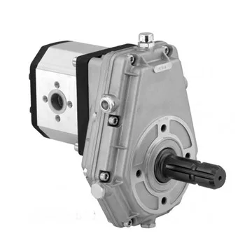
Model GP-PTO is a Power Take Off gear pump constructed with cast iron end plates and aluminium center section. It offers 4 displacement sizes from 3.41-9.76 in³/rev (56-160 cm³/rev). The standard drive is 1 3/8" diameter 6-tooth female spline.
Find the input horsepower (HP) required of the driven equipment. The power requirements of the driven equipment should be provided by the manufacturer of the driven equipment.
Establish the approximate engine speed desired during operation or PTO ratio (if known). PTO speed is stated as a percentage of engine speed. An example being the required pump speed of 1000 RPM and having an engine operating speed of 1500 RPM. The percentage of PTO to engine speed would be calculated to approximately two-thirds, or approximately 67 percent (e.g. 1000/1500 = 66.67, or 67%).
Determine the type and size of the PTO output required (i.e. driveshaft – the size of output required, direct mount pump – mounting flange and shaft type/size).
To further investigate what different PTOs are being offered, including the new 210 series PTO for the 2020 Ford Super Duty 10R140 Transmission, be sure to check out www.parker.com/chelsea to learn more.
DYNASET experts help you to find the perfect power take-off for your vehicle. Our selection covers installation kits of three partner companies, and we also offer tailored power take-offs. This ensures that your needs will be fully covered.
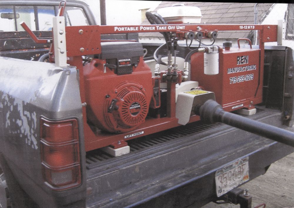
A belt drive PTO is for situations when a vehicle doesn’t have SAE or DIN-type attaching point for PTO. The power is taken from the crankshaft with the belt. The belt drive PTO can be installed into any vehicle and used while driving. Vans and pick-ups are standard vehicles for the belt drive PTO.
An engine PTO is used when the engine has SAE or DIN-type attaching point for the PTO. The engine PTO can be used while driving, and it can handle a lot of power. Most of the modern trucks have SAE or DIN-type attaching points for PTO. For example, refrigerated transports are one possible application for the engine PTO.
A transmission PTO can be installed if the transmission has SAE or DIN-type attaching point. The transmission PTO can be used while the vehicle is stationary. Applications like pipe cleaning units can be powered this way.
Split shaft PTO is implemented to the Cardan shaft, and it can be used while the vehicle is stationary. When the splitter is activated, the power is taken from the Cardan shaft to the piece of hydraulic equipment e.g. power washer.
A crankshaft coupling PTO can be used without SAE or DIN-type attaching point. This type of PTO can also be used while driving. It takes power straight from the crankshaft without a belt or so.
A power take-off or power takeoff (PTO) is one of several methods for taking power from a power source, such as a running engine, and transmitting it to an application such as an attached implement or separate machine.
Most commonly, it is a splined drive shaft installed on a tractor or truck allowing implements with mating fittings to be powered directly by the engine.
Semi-permanently mounted power take-offs can also be found on industrial and marine engines. These applications typically use a drive shaft and bolted joint to transmit power to a secondary implement or accessory. In the case of a marine application, such shafts may be used to power fire pumps.
In aircraft applications, such an accessory drive may be used in conjunction with a constant speed drive. Jet aircraft have four types of PTO units: internal gearbox, external gearbox, radial drive shaft, and bleed air, which are used to power engine accessories. In some cases, aircraft power take-off systems also provide for putting power into the engine during engine start.Coffman starter.
Also, in wave energy technology to harness the ocean wave energy, the power take-off systems are used. The working principle can vary and be classified as a direct mechanical drive system, hydro turbine transfer system, hydro motor system, pneumatic air turbine transfer system, and direct electrical drive system.
Various power transmission methods were available before power take-offs became common, but there were applications which would benefit more from some of the attributes that PTOs would provide. Flat belts were generally only useful for applications where the engine was stationary, such as factory steam engines, portable stationary engines, or traction engines parked in front of the work. For moving vehicles such as a traction engine or early tractor towing a farm implement, the implement could receive rotary power by taking it from one of its own wheels (whose turning was imparted by the towing) and distributing it via roller chains (to a sickle bar"s crank, for example), but such a transmission ceases if the vehicle stops traveling, and the workload"s resistance tends to make the wheel skid rather than turn, even if cleated. The concept of a shaft drive with easily connected and disconnected couplings, and flexibility for driving at changing angles (such as when an articulated tractor-and-trailer combination turns), was a goal to pursue.
Experimental power take-offs were tried as early as 1878, and various homemade versions were constructed over the subsequent decades.International Harvester Company (IHC) was first to market with a PTO on a production tractor, with its model 8-16, introduced in 1918.Case models. In 1920, IHC offered the PTO option on their 15-30 tractor, and it was the first PTO-equipped tractor to be submitted for a Nebraska tractor test. The PTO was a competitive advantage for IHC in the 1920s, and other companies eventually caught up with PTO implementation.
Inside the transmission, the exact point along the gear train where the power is taken off determines whether the PTO can be run independently of vehicle travel (ground speed). Early PTOs were often taken off the main output shaft, meaning that the vehicle had to be "in gear" in order to run the PTO. Later this was improved by so-called live PTO (LPTO) designs, which allow control of the PTO rotation independently of the tractor motion. This is an advantage when the load driven by the PTO requires the tractor motion to slow or stop running to allow the PTO driven equipment to catch up. It also allows operations where the tractor remains parked, such as silo-filling or unloading a manure spreader to a pile or lagoon rather than across a field. In 1945, Cockshutt Farm Equipment Ltd of Brantford, Ontario, Canada, introduced the Cockshutt Model 30 tractor with LPTO. Most PTOs built today
The PTO and its associated shafts and universal joints are a common cause of incidents and injury in farming and industry. According to the National Safety Council, six percent of tractor related fatalities in 1997 in the United States involved the PTO. Incidents can occur when loose clothing is pulled into the shaft, often resulting in bone fractures, loss of limb, or death to its wearer. On April 13, 2009 former Major League Baseball star Mark Fidrych died as a result of a PTO related accident; "He appeared to have been working on the truck when his clothes became tangled in the truck"s power take-off shaft", District Attorney Joseph Early Jr. said in a statement.
Two newer types, supporting higher power applications, operate at 1000 rpm and differ in shaft size. The larger shaft has 20 splines (diameter 1+3⁄4 in or 44 mm) (designated as Type 3), while the smaller has 21 splines (diameter 1+3⁄8 in or 35 mm) (designated as Type 2). Farmers typically differentiate these two types by calling them "large 1000" or "small 1000" as compared to the Type 1 which is commonly referred to as the "540".
Due to ever-increasing horsepower requirements from farm implements, and higher horsepower engines being installed in farm tractors, a still larger type (designated as Type 4) has been added to ISO 500. It operates at a higher rotational speed of 1300 rpm in order to allow for power transfer at reduced levels of torque. The shaft has 22 splines with a major diameter of 57.5 millimeters (mm). It is meant to handle PTO powers up to 450 kilowatts (kW), or roughly 600 horsepower (hp).
A 10-spline type was used with some early equipment such as the 1948 Land Rover. A six-spline adapter was usually supplied. It is customary for agricultural machines manufacturers to provide the nominal PTO power specification, an indication of the available instantaneous power at the shaft. Newer tractors may come equipped with 540/540E and/or 1000/1000E options that allow the tractor to power certain low-power-demand implements like hay rakes or tedders using lower engine speeds to maintain the revolutions per minute needed, using less fuel and placing less stress on the engine – thereby improving efficiency and reducing costs.
Truck transmissions have one or more locations which allow for a PTO to be mounted. The PTO must be purchased separately and care is required to match the physical interface of the transmission with a compatible PTO. PTO suppliers will usually require details of the make, model and even serial number of the transmission. Care is also needed to ensure that the physical space around the transmission allows for installation of the PTO. The PTO is engaged and disengaged using the main transmission clutch and a remote control mechanism which operates on the PTO itself. Typically, an air valve is used to engage the PTO, but a mechanical linkage, electric or hydraulic mechanism are also options.
Units will be rated according to the continuous and intermittent torque that can be applied through them and different models will offer different "PTO shaft rotation to engine RPM" ratios.
In the majority of cases, the PTO will connect directly to a hydraulic pump. This allows for transmission of mechanical force through the hydraulic fluid system to any location around the vehicle where a hydraulic motor will convert it back into rotary or linear mechanical force. Typical applications include:
A split shaft PTO is mounted to the truck"s drive shaft to provide power to the PTO. Such a unit is an additional gearbox that separates the vehicle"s drive shaft into two parts:
The unit itself is designed to independently divert the engine"s power to either the axle-facing shaft or the additional PTO output shaft. This is done by two independent clutches like tooth or dog clutches, which can be operated at total driveline standstill only. Because the main gearbox changes the rotation speed by selection of a gear, the PTO cannot be operated while the vehicle is moving.
A "sandwich" type split shaft unit is mounted between engine and transmission and used on road maintenance vehicles, fire fighting vehicles and off-road vehicles. This unit gets the drive directly from the engine shaft and can be capable of delivering up to the complete engine power to the PTO. Usually these units come with their own lubricating system. Due to the sandwich mounting style, the gearbox will be moved away from the engine, requiring the driveline to accommodate the installation.
NASA Technical Memorandum 101731; Monitoring Techniques for "X-29A Aircraft"s High Speed Rotating Power Takeoff Shaft"; David F Voracek, Ames Research Center, Dryden Flight Research Facility, Edwards, California, December 1990 nasa.gov
Quick, Graeme (March–April 2008). "Spinning an historical yarn about power-take-off shafts" (PDF). Australian Grain. Greenmount Press. 17 (6): 36–37. Archived from the original (PDF) on 2021-02-26. Retrieved 2022-07-28. [From p. 36] The medal for the very first recorded power take-off on a piece of mobile machinery on the other hand ought to go to an Aveling and Porter Bell-type reaper. This steam-powered outfit was put on show at the 1878 Universal Exposition in Paris.
Pripps, Robert N.; Morland, Andrew (photographer) (1993), Farmall Tractors: History of International McCormick-Deering Farmall Tractors, Farm Tractor Color History Series, Osceola, WI, USA: MBI, ISBN 978-0-87938-763-1.

Whether gear, vane, or piston pump, there may come a time when you have to replace your hydraulic pump. When your equipment isn’t working properly and you have narrowed the problem down to a hydraulic pump that needs to be replaced, what do you need to know?
The pump may simply be worn out—they do have a natural lifespan, as they are a wearable item in a hydraulic system. Although it is not possible to give an average lifespan given the different types of pumps and widely varying hours of operation; in general, you can expect many years of good operation from a hydraulic pump in most truck-mounted hydraulic systems. However, the life of a hydraulic pump might be much longer than what you are experiencing. Here are some questions you should ask:
Has the equipment been operating acceptably with this pump for a number of years without incident, and has the decline in performance been gradual over a longer period of time?
In this case, you’ll need to get the pump make and model number so that you can make sure that your replacement will be correct—either with an exact replacement or with another make that has the same operating specifications.
In any case, when replacing a failed hydraulic pump you will want to make sure to use this opportunity to also change out your hydraulic fluid (or at the very least use a filter cart and filter your oil). In the process of failing, your pump has introduced contaminants into your hydraulic system that you want to remove before they damage your new pump or any other hydraulic component. You will want to change your filter element(s) when you install your new pump, and then change it (them) out after a break-in period on your new pump.
If not, then let’s make sure there is not something else going on, or you may just find yourself replacing pumps frequently because the underlying problem hasn’t been addressed.
Input shaft is twisted/bcanroken: This occurs due to an extreme shock load to the pump. Typically, this happens when a relief valve is missing from the system, not functioning correctly, set to a much higher value than what the pump can withstand, or is too small for the system flow and thus cannot function correctly.
Shaft fretting:Fretting corrosion occurs under load in the presence of repeated relative surface motion, for example by vibration. Direct mount pump splines can be worn away. The solutions include:
Using larger pump and PTO shafts will not eliminate fretting, but may resolve the problem because of the increased metal available before the failure occurs.
Make sure that the pump is able to get a good flow of oil from the reservoir—pumps are designed to have the oil feed pushed to the pump by gravity and atmospheric pressure, not by “sucking” oil. If the oil level in the reservoir is lower than the inlet of the pump, or the run too long or uphill, oil may not flow adequately to the pump. You can check if the pump is receiving oil adequately by using a vacuum gauge at the pump inlet. For a standard gear pump, at maximum operating RPM, the gauge should read a maximum of 5 inches HG. Larger numbers will damage a gear pump, and if you have a piston pump, the maximum number will be lower for good pump life.
Over pressurization: Pressure relief settings may have been adjusted or changed, and are now higher than what the pump can withstand without causing damage.
Pumps don’t produce pressure, they produce flow and are built to withstand pressure. When the system pressure exceeds the pump design, failure begins—either gradually or catastrophically.
When installing the new pump, back all the relief settings off. Then with the use of a pressure gauge T’d in at the pump outlet, gradually adjust the pressure relief setting until a cylinder or motor begins to move. Once the cylinder has reached the end of its stroke, gradually increase the pressure relief setting until reaching the max system pressure (which would be the pressure rating of the lowest rated component in the system). Sometimes, if a pump has been replaced and is larger than the original (produces more flow), the relief may not be able to allow all the flow being produced to escape back to tank. When that happens, the relief valve is “saturated” and the effect is the same as having no relief in the system. Pressures can reach levels much higher than the relief settings and components can be damaged or destroyed.
Contamination: Over time, the system oil has gotten dirty or contaminated and no longer is able to lubricate the pump, or is carrying contamination to the pump.

The present invention relates generally to a hydraulic power coupling for agricultural equipment. More specifically, the invention relates to a hydraulic power coupling assembly for coupling a tractor power take-off (PTO) to various pieces of towed or stationary powered agricultural equipment.
Tractors are usually provided with a power take-off so that the power of the tractor can be used to drive various towed or stationary agricultural equipments, such seed planters, lime spreaders and the like. The equipment is connected to the power take-off shaft of the tractor. There have been numerous instances where the user has sustained serious injuries with entanglements with the power take-off shaft. The prior art discloses various safety devices, such as shields for the power take-off, as exemplified by the following patent art.
U.S. Pat. No. 3,507,347, issued on Apr. 21, 1970 to Marvin D. Bennett, describes a vehicle with a pump for delivering building materials such as plaster and a remote controlled power take-off for selectively powering the pump or the vehicle wheels. U.S. Pat. No. 3,717,045, issued on Feb. 20, 1973 to Thomas I. Burenga, describes a centrifugal pump assembly driven from the power take-off shaft of a farm tractor. U.S. Pat. No. 4,008,583, issued on Feb. 22, 1977 to Lewis Kle Davis, describes a swingable shield assembly for a tractor power take-off. U.S. Pat. No. 4,308,931, issued on Jan. 5, 1982 to Jagdish C. Khanna, describes a guard for a drive shaft in a farm tractor. U.S. Pat. No. 4,553,950, issued on Nov. 19, 1985 to Christian M. Teich, describes a flip-up shield assembly for a tractor power take-off. U.S. Pat. No. 4,665,768, issued on May 19, 1987 to Alexander Rashkovsky, describes a power take-off shaft shield assembly. U.S. Pat. No. 4,761,152, issued on Aug. 2, 1988 to Gerald L. Wagenbach, Jr., describes a foldable power take-off shaft shield. U.S. Pat. No. 5,311,961, issued on May 17, 1994 to Eugene E. Stabenow, describes a safety system for automatically shutting off the power take-off of a tractor in an emergency. U.S. Pat. No. 5,364,310, issued on November, 1994 to William Taylor, describes an attachment of a guard located around a power-off shaft extending between a tractor and a towed or mounted accessory or implement. Soviet Union Patent Document No. 1,751,587, dated Jul. 30, 1992, describes a system for automatic disconnection of the transmission of torque in agricultural equipment and a selectively open and closed protective guard. United Kingdom Patent Document No. 1,370,013, dated Oct. 9, 1974, describes a safety guard for a power take-off assembly. None of the above patents broadly disclose a hydraulic power coupling assembly for use with various pieces of agricultural equipment being powered, as defined by the present invention. Further, the cited prior art does not disclose a hydraulic power coupling assembly which includes a hydraulic pump mounted on the tractor PTO, a hydraulic motor mounted on a selected piece of agricultural equipment and quick-connect connectors among the pump, motor and the selected agricultural equipment. as defined by the present invention.
The present invention relates to a hydraulic power coupling assembly for coupling a tractor PTO to various pieces of towed or stationary powered agricultural equipment. The hydraulic assembly includes a hydraulic pump mounted on the tractor PTO, a hydraulic motor mounted on a selected piece of agricultural equipment and quick-connect connectors among the pump, motor and the selected agricultural equipment. The pump includes its own reservoir for oil or hydraulic fluid. A shield is incorporated into the pump to eliminate the need for a tractor mounted shield. The hydraulic assembly can be readily removed and transferred to another piece of agricultural equipment to be powered. Thus, the hydraulic assembly is readily available for any powered agricultural equipment needs, while at the same time, removing the exposure to the hazardous area of a tractor"s PTO drive unit.
Accordingly, it is a principal object of the invention to provide a hydraulic power coupling assembly for coupling a tractor PTO to various pieces of towed or stationary powered agricultural equipment.
It is another object of the invention to provide a hydraulic power assembly associated with a tractor PTO wherein the exposure to the hazardous area of the tractor"s PTO drive unit has been substantially eliminated.
It is a further object of the invention to provide a hydraulic power assembly associated with a tractor wherein the need for shielding at the connecting points between the tractor PTO and the powered agricultural equipment is substantially eliminated.
It is a still further object of the invention to provide a hydraulic power coupling assembly associated with a tractor PTO wherein the need for universal joints is substantially eliminated.
FIG. 1 is a perspective view of the hydraulic power coupling assembly associated with the tractor PTO for driving the towed or stationary agricultural equipment, in accordance with the present invention.
FIG. 3 is a perspective view of the brackets connecting the "A" frame beams to the bottom of the hydraulic motor housing, in accordance with the present invention.
In its broadest aspect the present invention is a hydraulic power coupling for coupling a tractor PTO to various pieces of towed or stationary powered agricultural equipment. The hydraulic power coupling assembly includes a hydraulic pump mounted on the power take-off shaft of the tractor, a hydraulic motor mounted on a selected piece of agricultural equipment being powered, quickconnect hose couplings between the pump and the motor, and quickconnect connectors between the selected piece of towed or stationary agricultural equipment and the coupling assembly.
With reference to FIGS. 1-2, there is illustrated a hydraulic power coupling assembly associated with a power take-off (PTO) shaft 10 of a tractor 12 for use with a particular piece of agricultural equipment which is powered for operative use. The example of an agricultural equipment that is disclosed for purposes of discussion is a wheeled spreader 14 for spreading a granular material and the like.
The hydraulic power coupling assembly includes a hydraulic pump housing 16 which is supported on the tractor 12 by suitable support means. A hydraulic pump 18 is mounted within the hydraulic pump housing 16 and is operatively connected with the PTO shaft 10 of the tractor 12. A hydraulic fluid reservoir 20 is mounted on the hydraulic pump 18. The hydraulic fluid reservoir 20 provides make-up fluid and deals with potential surges of the hydraulic pump 18. A conventional shield member (not shown) is incorporated within the hydraulic pump housing 16 thereby eliminating the need for a shield being directly associated with the PTO shaft 10 of the tractor 12. Also, the hydraulic pump housing 16 includes therein, a first inlet conduit 22 and a first outlet conduit 24. Each of the first inlet and outlet conduits 22, 24 is operatively respectively connected with the hydraulic pump 18 and includes a first quick-connect coupling member 26 mounted on the wall of the hydraulic pump housing 16. A hydraulic supply hose 28 is connected with the first hydraulic pump outlet conduit 24 via the respective first quick-connect coupling member 26. A hydraulic fluid return hose 30 is connected with the first inlet conduit 22 via the respective first quick-connect coupling member 26. A hydraulic motor housing 32 is supported by the towed spreader 14. The hydraulic motor housing 32 has a second inlet conduit 34 and a second outlet conduit (not shown). Each of the second inlet and outlet conduits respectively has second quick-connect coupling members (not shown) mounted on the hydraulic motor housing 32. The second quick-connect coupling members are similar to the first quick-connect coupling members 26. Each of the hydraulic supply and fluid return hose members 28, 30 respectively being of such length that each of the hose members can respectively be attached to the second quick-connect hose couplings on the hydraulic motor 32. A hydraulic motor 36 is mounted within the hydraulic motor housing 32 and is operatively connected via a rotating driven shaft 38 to a driven shaft 40 of the spreader 14. The rotating driven shaft 38 substantially duplicates the function of the PTO shaft 10. Thereby the rotating blades of the spreader 14 are powered by the PTO shaft 10 via the appropriate drive components of the hydraulic assembly.
The spreader 14 includes a supporting conventional A-shaped or "Al" frame 42, a base 44 mounted on the frame 42, a hopper 46 and a bracket 48 is mounted on the base 44 for holding the hopper 46 in an upright position. In FIG. 3, a pair of standard U-shaped brackets 50 bolts A-frame beams 52 to the bottom of the hydraulic motor housing 32. These types of bottom bracket fasteners provide a quick and easy structural arrangement of attaching the hydraulic assembly to any standard piece of towed or stationary agricultural equipment; that is, the user can purchase just one hydraulic power coupling assembly and use it on various pieces of towed or stationary agricultural equipment. The A-frame 42 is connected by a rod 54 which has a coupling 56 that attaches to a trailer hitch 58 of the tractor 12. Rotatable blades (not shown) are mounted in the hopper 46 for spreading the granular material from the hopper 46. The blades are rotated by the spreader shaft 40 which is powered via the hydraulic motor shaft 38.
Thus, the hydraulic power coupling assembly can readily be removed when the tractor is not in use and can be transferred to the next piece of agricultural equipment to be powered. Accordingly, the invention is comprised by having the hydraulic power coupling assembly readily available for any powered agricultural equipment need while at the same time, removing the hazardous exposure to the PTO drive unit.
Various modifications may be made to the present invention. For example, a remote controlled device, such as a voice-controlled remote controlled device may be utilized in conjunction with the hydraulic power coupling assembly of the present invention.

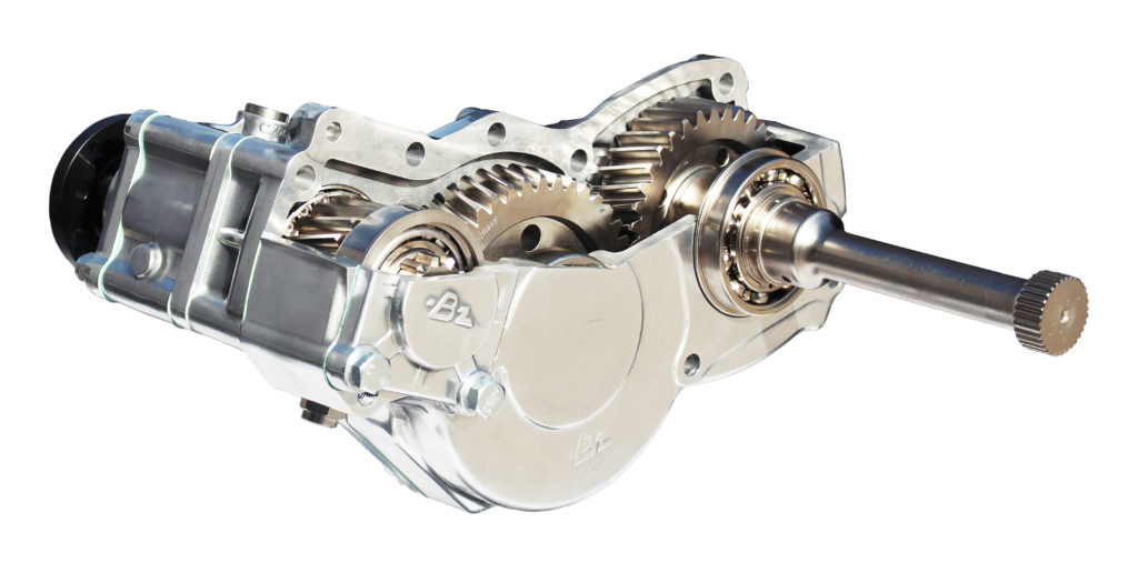
Abstract: A power take-off includes an input mechanism having an input gear that is rotatably supported on a housing of the power take-off portion. The input mechanism also has a portion that extends outwardly through the opening provided through the mounting surface of the housing of the power take-off portion and that is adapted to extend within and be rotatably driven by the source of rotational energy. The power take-off further includes an output mechanism that is disposed within the housing and includes a driven gear that is rotatably driven by the input gear of the input mechanism. A rotational axis of the input gear and a rotational axis of the driven gear are misaligned so as to minimize the transmission of torque transients and other vibrations therethrough during operation.
Abstract: A transaxle for use as a drive apparatus of a vehicle is provided. The transaxle includes a main housing joined to a gear housing to enclose a transmission and a reduction gear set. The transmission includes a pump assembly and a motor assembly arranged in a parallel configuration on one side of a center section. A charge pump is contained within a pocket on an opposing side of the center section. A charge pump cover assembly secures the charge pump in the pocket and has a charge relief assembly that extends into a void volume defined by a ring gear of the gear reduction set. The gear reduction set drives an axle extending from the gear housing.
Abstract: The present invention provides improved, real time sensing of pressure supplied to the hydraulic operator of a clutch for a motor vehicle driveline power take off. A proportional sensor in the hydraulic line to the power take off clutch actuator provides a data signal in real time of the actual pressure applied to the clutch actuator. This signal is provided to the power take off control module (PCM) and/or to the transmission control module (TCM). The power take off control module, having instantaneous data regarding the pressure applied to the hydraulic operator achieves two important operating functions: monitoring and feedback.
Abstract: A power take-off unit (“PTO”) may include a damper to reduce noise while the PTO is operating at low torque or at low RPM. The damper may also be located in the transmission before the PTO driver gear. A method may be used to systematically measure the frequency and/or amplitude of the vibrations that cause noise and to adjust the damping constant of a damper to reduce the noise.
Abstract: A hybrid vehicle drive system for use with a first prime mover and a transmission driven by the first prime mover. The system includes a second prime mover coupled to a rechargeable energy source, a split shaft PTO, and an accessory coupled to the split shaft PTO. The split shaft PTO is configured to couple to the second prime mover, and the accessory is configured to receive power from the second prime mover through the split shaft PTO.
Abstract: A drive apparatus driven by a prime mover and having a variable speed transmission disposed within a housing is disclosed. A power take off is driven by an output shaft of the prime mover and selectively drives a power take off output shaft. The variable speed transmission drives a transmission output shaft, which in turn drives a first clutch mechanism and a second clutch mechanism. A first drive axle is engaged to and selectively driven by the first clutch mechanism and a second drive axle is engaged to and selectively driven by the second clutch mechanism.
Abstract: A mounting surface of an agricultural work vehicle power takeoff system. In one example, an agricultural vehicle includes a power takeoff (PTO) device. The PTO device includes a drive shaft and a mounting surface. Furthermore, the mounting surface includes a plurality of threaded apertures for coupling an auxiliary system to the PTO device, and a pilot configured to engage with a complimentary pilot of the auxiliary system to facilitate alignment of the PTO device with the auxiliary system. The mounting surface and the auxiliary system have the same mounting configuration.
Abstract: A power take-off system for an internal combustion engine that has a drive gear positioned within a crankcase includes a housing. The housing is coupleable to the internal combustion engine. The system also includes an input gear with a drive gear engagement portion, a toothed portion, and a shaft extending between the drive gear engagement portion and the toothed portion. The input gear is coupled to the housing such that the driver gear engagement portion is positioned within the crank case and the toothed portion is positioned within the housing. The input gear also includes a vent conduit that extends through the shaft. The vent conduit includes a first end open to the housing and a second end open to the crankcase.
Abstract: A firefighting pump transmission for use with an emergency vehicle pump comprising a housing receiving a drive shaft, the drive shaft having a PTO gear affixed thereto within the housing, an impeller shaft for turning an impeller of a pump, and means for selectively powering the impeller shaft from the drive shaft, the means for powering may include a multi-disk clutch. The transmission allows for powering the PTO gear while the impeller shaft is idle. A Commercially Available PTO device may be mounted to the housing to power a variety of devices.
Abstract: A hydraulic system is provided for a hydraulic shifter assembly of a split shaft assembly having a power take off system and utilized on a vehicle that has an automatic transmission and limited access to the transmission—preventing a direct connection of a power take off to the transmission. The hydraulic system provides hydraulic pressure from the transmission to the hydraulic shifter assembly and back to the transmission from the hydraulic shifter assembly. The system also provides hydraulic pressure from the transmission to the power take off.
Abstract: A drive apparatus driven by a prime mover that has a prime mover output shaft is disclosed. The drive apparatus has a housing and a power take off. The power take off is driven by the prime mover output shaft and selectively drives a power take off output shaft. The drive apparatus further has a variable speed transmission disposed within the housing. The variable speed transmission drives a transmission output shaft, which in turn drives a first clutch mechanism and a second clutch mechanism. A first drive axle is engaged to and selectively driven by the first clutch mechanism and a second drive axle is engaged to and selectively driven by the second clutch mechanism.
Abstract: A kinetic energy system incorporates multiple flywheels, each flywheel situated and adapted to develop and store kinetic energy, and to subsequently impart that energy to move a work machine. Each flywheel is controlled by an ECM to operate in a selective sequence with respect to any of the other flywheels. Each flywheel has its own individual external gear and clutch unit adapted to be in communication with a commonly shared continuously variable transmission. The plurality of flywheels may be operated sequentially to develop, store, and dispense kinetic energy equivalently to that of a substantially larger unitary flywheel. In the disclosed embodiment and method of operation, the flywheel system may be employed with a traditional internal combustion engine to produce a hybrid motive source, with capability for effectively meeting transient load demands of an off-road work machine.
Abstract: A secondary drive device of a mobile working appliance with an electronic control unit for actuating a power take-off shaft clutch arranged between a transmission and a power take-off shaft is disclosed. According to the disclosure, the control unit is designed with a flange-mounting function unit which, when activated, executes a rotary position correction of the power take-off shaft with respect to the drive shaft. Furthermore, a method for coupling and/or uncoupling a working machine to/from the secondary drive device of a mobile working appliance as an energy source is proposed.
Abstract: A vehicle PTO driveline (10) in which a PTO input shaft (11) drives a PTO wet clutch (12) which when engaged drives a PTO output shaft (13). The driveline has an eccentric formation (34) on the input shaft (11) which oscillates a pumping piston (31) when the input shaft rotates, which piston pumps cooling/lubricating fluid from a reservoir (25c) to the wet clutch (12). The piston is connected with the eccentric formation by a ring (33) which surrounds the eccentric formation (34) and a hollow tube (32) which is attached to the ring and which carries the piston at a lower end, the piston oscillating inside a chamber (31a) when the input shaft rotates. The chamber (31a) is connected with the fluid reservoir (25c) and the oscillating piston pumps the fluid along the hollow tube (32) into the ring (33) which then delivers the fluid into internal passages (38) in the input shaft from where the fluid flows to the wet clutch.
Abstract: A power take-off unit (“PTO”) may include a retarder to reduce noise while the transmission PTO output gear is operating at low torque. The retarder may variably load the PTO based on the PTO output load, while disengaging from the PTO while the PTO is not operational. The retarder may also serve as a primary retarder function to slow a vehicle"s speed. The retarder may be controlled by a vehicle operator or by a processor.
Abstract: A mounting surface of an agricultural work vehicle power takeoff system. In one example, an agricultural vehicle includes a power takeoff (PTO) device. The PTO device includes a drive shaft and a mounting surface. Furthermore, the mounting surface includes a plurality of threaded apertures for coupling an auxiliary system to the PTO device, and a pilot configured to engage with a complimentary pilot of the auxiliary system to facilitate alignment of the PTO device with the auxiliary system. The mounting surface and the auxiliary system have the same mounting configuration.
Abstract: A tractor power take-off drive line having an output shaft (11) with a socket (12) within which a removeable PTO stub shaft (13) is drivingly received. The stub shaft is retained in the socket by radially moveable retaining members (16) housed in the output shaft and moveable between a radially inward retaining position in which the retaining members each projecting into the socket (12) to engage a retaining formation (18) in the stub shaft (13) within the socket and a radially outward releasing position in which the retaining members are free to move radially outwardly relative to the socket to disengage the retaining formation and allow the stub-shaft to be removed from the socket.
Abstract: A method of operating a drive-train of a motor vehicle having a hybrid drive with an internal combustion engine and an electric machine, an electrical energy accumulator that can be charged when the electric machine operates as a generator and discharged when the electric machine operates as a motor, a transmission connected between the hybrid drive and a drive output, and at least one auxiliary power takeoff on either the transmission or the hybrid drive side such that the auxiliary power takeoff can be operated with variable energy demand within functional capability limits that depend on the auxiliary power takeoff. Depending on the current operating status of the hybrid drive unit, the electrical energy accumulator and/or the auxiliary power takeoff, energy available in the drive-train, but not required at the drive output, can bypass the electrical energy accumulator and be stored in the auxiliary power takeoff.
Abstract: A kinetic energy system incorporates multiple flywheels, each flywheel situated and adapted to develop and store kinetic energy, and to subsequently impart that energy to move a work machine. Each flywheel is controlled by an ECM to operate in a selective sequence with respect to any of the other flywheels. Each flywheel has its own individual external gear and clutch unit adapted to be in communication with a commonly shared continuously variable transmission. The plurality of flywheels may be operated sequentially to develop store, and dispense kinetic energy equivalently to that of a substantially larger unitary flywheel. In the disclosed embodiment and method of operation, the flywheel system may be employed with a traditional internal combustion engine to produce a hybrid motive source, with capability for effectively meeting transient load demands of an off-road work machine.
Abstract: The subject is a rotary drive device (1), which has a device housing (7) in which drive means (2) are disposed that are in driving communication with a rotatably supported power takeoff part (4). The power takeoff part (4) has a power takeoff disc (5) that is received at least partly in a bearing receptacle (25) of the device housing (7), the power takeoff disc being surrounded by an annular roller bearing unit (33). The roller bearing unit has a bearing assembly (34) with rolling elements (35) and with one inner and one outer running surface arrangement (37, 38), and the entire bearing assembly (34) is disposed inside the bearing receptacle (25) and is surrounded radially outward by a boundary wall portion (27) of the device housing (7).
Abstract: A power take-off for compressors, comprising: a first rotating element (2), predisposed to be connected on command to a motor (40); at least a second rotating element (3), kinematically connected to the first rotating element (2), which is predisposed to be connected to a first user (50); a torque limiter or clutch (4), interposed between the first rotating element (2) and the second rotating element (3).
Abstract: Embodiments which selectively engage a motor with auxiliary equipment and a final drive assembly of the motor vehicle are disclosed. A transmission of such a motor vehicle may include a transmission input shaft to receive power from the motor, a transmission output shaft, and clutches and associated gears that define power delivered by the transmission output shaft based upon power received by the transmission input shaft. An auxiliary gearbox may include a transmission input gear associated with the transmission output shaft, an equipment output gear to power the auxiliary equipment, and a drive output gear to power the final drive assembly. The motor vehicle may further include a transmission control module to engage the transmission input gear with the equipment output gear by transitioning among locking the transmission output shaft, disengaging the clutches to reduce torque on the transmission output shaft, and placing the transmission in an unlocked neutral state.
Abstract: A modular drive system for a zero turn radius vehicle having a central gear box with a vertical input shaft, a central drive train that powers a variety of left and right side drive mechanisms, and a power take off mechanism having a clutch and brake assembly. The vertical input shaft is a through-shaft design that allows the central gear box to be mounted with either end of the through-shaft oriented in an upward direction. A screw-on filter acts in conjunction with a charge pump to remove debris from the central gear box"s hydraulic fluid.
Abstract: A hydraulic pump device for a work vehicle having a transmission case that houses a PTO shaft (12) comprises: a hydraulic pump (35), a pump input shaft (36) of the hydraulic pump (35) that has a projecting shaft portion projecting into the transmission case (1), a first bevel gear (41), and a second bevel gear (42). The first bevel gear (41) is fitted on the PTO shaft (12) and the second bevel gear (42) is connected to the projecting shaft portion. A holder (38) for supporting the PTO shaft (12) is removably attached to the transmission case (1). The first bevel gear and the second bevel gear are supported to the holder for rotation about respective axes.
Abstract: Embodiments which selectively engage a motor with auxiliary equipment and a final drive assembly of the motor vehicle are disclosed. A transmission of such a motor vehicle may include a transmission input shaft to receive power from the motor, a transmission output shaft, and clutches and associated gears that define power delivered by the transmission output shaft based upon power received by the transmission input shaft. An auxiliary gearbox may include a transmission input gear associated with the transmission output shaft, an equipment output gear to power the auxiliary equipment, and a drive output gear to power the final drive assembly. The motor vehicle may further include a transmission control module to engage the transmission input gear with the equipment output gear by transitioning among locking the transmission output shaft, disengaging the clutches to reduce torque on the transmission output shaft, and placing the transmission in an unlocked neutral state.
Abstract: An apparatus comprising a power take-off shaft includes an outer shaft and an inner shaft. The outer shaft includes an outer periphery and an inner periphery. The inner shaft includes an outer periphery and an inner periphery. A notch is configured around at least a portion of the outer periphery of the inner shaft, and a self-lubricating material is disposed on at least a portion of the notch.
Abstract: A transmission device for a work vehicle, comprising a travel drive system for transmitting engine power to a travel device; an implement drive system for transmitting engine power to an external power take-off shaft; braking operation tools for a braking operation; a stop operation mechanism provided to the travel drive system and capable of interrupting the transmission of power to the travel device; and a hydraulically operated PTO clutch for interrupting the transmission of power to the external power take-off shaft, the PTO shaft being provided to the implement drive system; wherein the stop operation mechanism and the PTO clutch are linked with the braking operation tools so that the stop operation mechanism is operated to a power transmission stopping position and the PTO clutch is disengaged along with a pressing operation of the braking operation tools, and the PTO clutch is engaged along with a press-releasing operation of the braking operation tools; and an operation timing is set so that the PT
Abstract: A shift device for a power take-off transmission. An input shaft is connectable to an output shaft with three gear pairs. The output shaft has a recess, in which a PTO stub shaft can be reversibly introduced. A mechanism, actuated by a PTO stub shaft actuates a gearshift sleeve, provided on the output shaft and rotationally fixed to the output shaft, is provided on the output shaft. In one shift position of the gearshift sleeve is rotationally fixed to a gear wheel of a first gear pair. In another shift position of the gearshift sleeve no fixed connection exists between the gearshift sleeve and gear wheel of the first gear pair. By means of a further gearshift sleeve a rotationally fixed connection can be established with a gear wheel of the second or the third gear pair.
Abstract: The subject is a rotary drive device (1), which has a device housing (7) in which drive means (2) are disposed that are in driving communication with a rotatably supported power takeoff part (4). The power takeoff part (4) has a power takeoff disc (5) that is received at least partly in a bearing receptacle (25) of the device housing (7), the power takeoff disc being surrounded by an annular roller bearing unit (33). The roller bearing unit has a bearing assembly (34) with rolling elements (35) and with one inner and one outer running surface arrangement (37, 38), and the entire bearing assembly (34) is disposed inside the bearing receptacle (25) and is surrounded radially outward by a boundary wall portion (27) of the device housing (7).
Abstract: The invention relates to a gear brake device for a multi-speed manual transmission (2), comprising a gear brake (16) that is arranged outside the transmission housing, that is led out of the transmission housing, and which has a power take-off shaft that is drive-connected or can be drive-connected with an input side gear shaft arrangement, said gear brake performing a synchronization function during up-shifting of the transmission in the known manner. According to the present invention, at least one PTO connection (20) with a drive connection to the power take-off shaft (12) is arranged downstream of the gear brake (16), so that the power take-off shaft (12) is also available for a PTO function.
Abstract: A power take-off (PTO) includes new features to make it more environmentally friendly, improve service life, and reduce service part inventory. The idler shaft, which holds the pick-up gear for connecting the PTO to a transmission, may include a splined shaft. The pick-up gear and an idler gear may be mounted on the splined in different configurations. The output of the PTO, including a splined output and an output plate for connecting to secondary equipment such as a hydraulic pump, can be easily replaced or reconfigured to work with different configurations of secondary equipment.
Abstract: An insulation application system is provided that utilizes a sole power source to drive the system"s multiple components. In one embodiment the system includes an insulation blower, a hydraulic drive, an electrical generator, and a vacuum fan that is powered by a power-take-off.
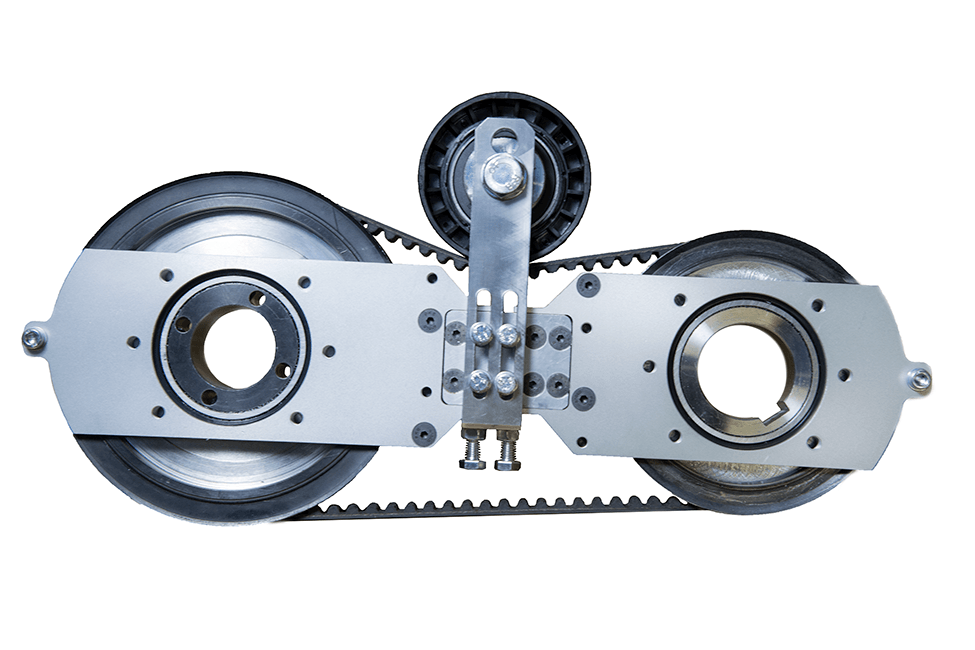
Abstract: A pass-through power take-off (PTO) mechanism for use with renewable energy systems is described to extract power from a linearly moving tether under high tension and to convert it to rotary power such as for driving an electric generator. Three such embodiments are described. The first uses two adjacent timing belts and transfers power from tether to PTO via friction. The second embodiment uses two adjacent roller chain loops and a mechanical engagement method to transfer power from tether to PTO. The third embodiment uses two adjacent double-sided timing belts and either a synchronous or an asynchronous method to transfer power from the tether to the PTO.
Abstract: A motor vehicle power take off system for a motor vehicle engine includes a viscous coupling. The input rotor of the viscous coupling is provided with a variable geometry impeller section which allows direct control over the proportion of input torque on the input shaft transferred to the viscous fluid and thereby to an output shaft. Both passive and active control schemes are proposed.
Abstract: A rotary lawn mower includes an internal combustion engine having a power take-off. The mower further includes a connector adaptor attached to the power take-off, and a lawn mower blade. A connector base of the mower is attached to the blade. The connector base and the connector adaptor have extensions designed to interlock the connector base with the connector adaptor. At least one of the extensions forms a J-shaped structure arranged longitudinally along an axis of rotation of the connector base and connector adaptor.
Abstract: A PTO clutch for a work vehicle and an operating structure for the PTO clutch includes: a PTO clutch having a clutch member and receiving drive power from an engine; a clutch control mechanically coupled to the clutch member for manually operating the PTO clutch via the clutch member; a PTO brake disposed downstream of the PTO clutch with respect to a direction in which power is transmitted, the PTO brake being movable to a braking position in association with a clutch disengaging operation of the clutch member; and a control retaining device for retaining the clutch control at a clutch disengaging position.
Abstract: A motor vehicle including an internal combustion engine, which utilizes a power take-off mechanism, that converts the reciprocating linear motion of the piston into reciprocating angular motion of the gearing cylinder, being in gear with the partially teethed connecting rod via right angled teeth and rotating motion of the drive shaft which runs coaxially through the gearing cylinder and vice versa. The mechanism has means for causing the piston to pause while the drive shaft rotates. The motor vehicle comprises a fuel heater, an exhaust cleaner including a sinuous tube and liquid for separating impure components of exhaust, a main control module controlling the function of the engine and piston function, a second control module controlling the engine during the minimal running state, thus controlling the pause time of the piston, a third control module controlling the energy flow to the heater, the fuel feeder, and the air feeder.
Abstract: A vehicle drive train for transferring torque to first and second sets of wheels includes a first driveline adapted to transfer torque to the first set of wheels and a first power disconnection device. A second driveline is adapted to transfer torque to the second set of wheels and includes a second power disconnection device. A hypoid gearset is positioned within one of the first driveline and the second driveline in a power path between the first and second power disconnection devices. The hypoid gearset is selectively disconnected from being driven by either of the first driveline and the second driveline when the first and second power disconnection devices are operated in a disconnected, non-torque transferring, mode.
Over the years, revolutionary advancements have been instigated in the tractor control systems’ field. These changes are primarily attributed to integrating various hydraulic inventions in the tipping trailer, braking system, implementing control structure, and steering to enhance this machinery’s optimum functionality. Hydraulic flow and pressure can be translated to motion and forces that enhance a tractor’s capacity to execute tasks that operators cannot perform manually or physically (Gannon, 2017). This paper provides a comprehensive discussion of tractor hydraulics and highlights the benefits of this particular technology.
There are two forms of hydraulic systems: the open- and closed-center structures. The latter is typical in modern-day farm equipment; this includes most tractor models. When in neutral, this system’s closed center valve obstructs oil flow from the pump. This fluid travels to an accumulator, which typically stores it under pressure. The valves also block fluid flow via the center when the hydraulic is in the aforementioned state. A variable flow pump also halts its operation following the closure of the valve. Open hydraulic structures were commonly used in most of the preliminary tractors. When in neutral, this system’s open-center valves link all lines back to the reservoir, directly bypassing the pump, which is always in operation, fostering the constant flow of oil without accumulating pressure. Valves also allow the flow of fluid through the center and into the reservoir during this particular.
Hydraulic oil, particularly non-pressurized fluid, is usually stored in the reservoir. According to Moinfar and Shahgholi (2018), reservoirs are usually vented towards the atmosphere to acclimatize the changing levels of oil. The air vent is fitted with filters to impede the entry of dust or dirt into the reservoir. The reservoir’s metallic walls enhance the cooling process of the fluid by improving the outflow of heat. The decreased pressure within this structure also gives room for dissolved or trapped air to escape from the hydraulic fluid. A sufficient surface area is also essential to foster the dispersal of heat.
JIC and NPTF fittings prevent hydraulic components’ port leakage. NPTF taper pipe threads hinder seepage by using the male-to-female resistance thread taper. On the other hand, JICs sue O-ring (Moinfar & Shahgholi, 2018). The brake hydraulic system’s components are usually joined using hoses and lines. The latter connects the hydraulic system’s stationary parts while hoses consolidate in motion. The hose, tubing, or pipe’s size is crucial (Moinfar & Shahgholi, 2018). If the hose’s size is minimal, the flow of oil increases rapidly, generating heat and causing the fluid to lose power. The cost and time for installing a large hose, on the other hand, can be too high.
The hydraulic pump plays a crucial role in enhancing fluid transmission from the reservoir and towards the hydraulic system. This process elevates the fluid’s energy level by triggering significant surges in its pressure. A one-phase pump typically has a single flow rate and one maximal pressure. These pumps are usually attached to the PTO shaft or crankshaft on a farm tractor. These pumps are often fitted on manual loaders and backhoes. On the other hand, a two-step pump first generates high fluid volumes by enhancing the cylinder’s rapid in-and-out movements. In case of any form of resistance, an additional gear set is used to create high pressure for splitting and lifting. Nonetheless, the fluid’s volume will reduce significantly during this phase.
Examples of valves fitted in the hydraulic system of a tractor include the flow, pressure, and direction control valve. They function by stopping or impeding liquid or pressure flow and controlling the quantity, pressure, and direction of flow. The motor is located within the pump’s power source, i.e., the cylinder. The fluid with high-pressure levels exerts its action on the piston and rod located within the hydraulic cylinder (Gosaye et al., 2015). Each cylinder stroke converts or translates the power or pressure of the fluid into mechanical force or work. While the piston and rod extend, the reservoir’s oil levels decrease, and when these two devices retract, the fluid flows back to the reservoir.
The pressure is typically applied or exerted on one region of the piston in single-acting cylinders; thus, mechanical force occurs in a single direction only. The cylinder then assumes its initial position under the load’s weight. Contrarily, pressure may be exerted on both sides of the piston in double-acting cylinders. Consequently, work takes place in either direction. The fixed ends in welded cylinders are usually welded to increase the durability and strength for high-pressure functions. Four rods are typically used to hold tie-rod cylinders together.
The instigation of hydraulics triggered significant changes in the agricultural industry, especially concerning the manner and method of production. The adoption of this technology has triggered substantial reductions in the level of manual power or effort needed to perform farm-related activities both in terms of work animals and workers (“How Hydraulics Transformed,” 2019). The tractor has also been effective in decreasing the risks associated with farm-related injuries by minimizing the number of hours individuals spend working in agricultural fields. This invention has also helped restrict the downtime rate amid agricultural operations. Furthermore, it has been crucial in promoting personal and overall productivity and efficiency during practice.
Significant advancements in agricultural engineering, particularly in tractor hydraulics, have triggered farm-related practices’ efficacy and efficiency. The tractor hydraulic system has several components, including the reservoir, pump, and motor. Hydraulics foster a tractor operator’s capacity to execute tasks that demand substantial effort with an electrical switch flip or simple lever push, which, in turn, actuates the hydraulic circuit. Contemporary farming integrates the use of hydraulics for operations that were initially controlled by mechanical means.
Gosaye, C., Mengiste, Z., & Hailu, A. (2015). Evaluation of the compatibility of tractors and implements at Tendaho Sugar Estate. ARPN Journal of Science and Technology, 5(10), 476–483. Web.


 8613371530291