
pressure compensated hydraulic pump supplier

A pressure compensator is a device built into some pumps for the purpose of automatically reducing (or stopping) pump flow if system pressure sensed on the pump outlet port, should rise above a pre-set desired maximum pressure (sometimes called the "firing" pressure). The compensator prevents the pump from being overloaded if an overload is placed on the hydraulic system.
A compensator is built into the pump at the factory and usually cannot be added in the field. Any pump built with variable displacement can be controlled with a compensator. These include several types of axial piston pumps and unbalanced (single lobe) vane pumps. Radial piston pumps can sometimes be built with variable displacement but do not lend themselves readily to this action. Most other positive displacement pumps including internal and external gear, balanced (double lobe) vane, gerotor, and screw types cannot be built with variable displacement.
Figure 1 is a schematic of a check valve axial piston pump, variable displacement, controlled with a pressure compensator. The pistons, usually 5, 7, or 9 in number, are stroking inside a piston block which is keyed to and is rotating with the shaft. The left ends of the pistons are attached through swivel joints, to piston shoes which bear against and slide around on the swash plate as the piston block rotates. The swash plate itself does not rotate; it is mounted on a pair of trunnions so it can swivel from neutral (vertical) position to a maximum tilt angle. The angle which the swash plate makes to the vertical causes the pistons to stroke, the length of stroke being proportional to the angle. Normally, at low system pressures, the swash plate remains at its maximum angle, held there by spring force, hydraulic pressure, or by the dynamics of pump construction, and pump flow remains at maximum. The compensator acts by hydraulic pressure obtained internally from the pump outlet port. When pump pressure rises high enough to over-come the adjustable spring behind the compensator piston, the "firing" pressure has been reached, and the compensator piston starts to pull the swash plate back toward neutral, reducing pump displacement and output flow. The spring in the compensator can be adjusted for the desired maximum or "firing" pressure.
Under working conditions, on a moderate system overload, the compensator piston reduces the swash plate angle just enough to prevent the system pressure from exceeding the "firing" pressure adjusted on the compensator. On severe overloads the compensator may swing the swash plate back to neutral (vertical) to reduce pump flow to zero.
Maximum Displacement Stops. Some pumps are available with internal stops to limit the tilt angle of the swash plate. These stops limit the maximum flow and limit the HP consumption of the pump. They may be fixed stops, factory installed and inaccessible from the outside, or they may be externally adjustable with a wrench.
Manual Control Lever. Some pressure compensated pumps, especially hydrostatic transmission pumps, are provided with an external control lever to enable the operator to vary the swash plate angle (and flow) from zero to maximum. On these pumps the pressure compensator is arranged to override the manual lever and to automatically reduce the swash plate angle if a system overload should occur even though the operator control lever is still shifted to maximum displacement position.
Basically the pressure compensator is designed to unload the pump when system pressure reaches the maximum design pressure. When the pump is unloaded in this way, there is little HP consumed and little heat generated even though pressure remains at the maximum level, because there is no flow from the pump.
Variable displacement pumps are usually more expensive than fixed displacement types, but are especially useful in systems where several branch circuits are to be supplied from one pump, and where full pressure may be required simultaneously in more than one branch, and where the pump must be unloaded when none of the branches is ill operation. If individual 4-way valves are used in each branch, each valve must have a closed center spool. The inlet ports on all 4-way valves must be connected in parallel across the pump line. However, if all branch circuits are operated from a bank valve of the parallel type, a pressure compensated variable displacement pump may not be necessary; a fixed displacement pump, gear, vane, or piston, may serve equally well because the bank valve will unload the pump when all valve handles are placed in neutral, but when two or more handles are simultaneously shifted, their branch circuits will automatically be placed in a parallel connection.
As in all hydraulic systems, more pump oil will flow to the branch with the lightest load. Bank valve handles can be modulated to equalize the flow to each branch. When individual 4-way valves are used in each branch, flow control valves may be installed in the branch circuits and adjusted to give the flow desired in each branch.
Figure 2 shows a multiple branch circuit in which a variable displacement pump is used to advantage. Individual 4-way valves, solenoid operated, are used for each branch, and they have closed center porting. Please refer to Design Data Sheet 54 for possible drift problems on a pressure manifold system. A pressure relief valve is usually required even with a pressure compensated pump due to the time interval required for the swash plate to reduce its tilt angle when a sudden overload occurs. The relief valve will help absorb part of the pressure spike generated during this brief interval. It should be adjusted to crack at about 500 PSI higher than the pressure adjustment of the compensator piston spring to prevent oil discharge across it during normal operation.
All hydrostatic transmission systems use a variable displacement pump with pressure compensator, and often combine the compensator with other controls such as the horsepower input limiter, load sensing, flow sensing, or constant flow control.

Hydraulic pumps are an incredibly important component within hydraulic systems. IFP Automation offers a variety of pump and hydraulic system products that deliver exceptional functionality and durability. Our partner Parker’s extensive line of hydraulic pumps deliver ideal performance in even the most demanding industrial and mobile applications. In this post, we are going to spend time discussing pressure compensated and load sensing hydraulic pumps.
Do to the surface area of the servo piston and the pressure exerted on that area, a force is generated that pushes the swash plate of the pump to a lower degree of stroke angle.
The pump tries to maintain compensator setting pressure, and will provide whatever flow (up to it’s maximum flow rate) that is necessary to reach that pressure setting.
For more information on how you can make use of hydraulic pump technology in your applications, please contact us here to receive a personalized contact by an IFP Application Engineer:

Drop in equivalent to Vickers 02-341804 hydraulic pressure compensated piston pump 19.48 GPM @ 1800 RPM 3000 PSI.3000 PSI maximum operating pressure. 2400 RPM maximum RPM.

Drop in equivalent to Vickers 02-341818 hydraulic pressure compensated piston pump 19.48 GPM @ 1800 RPM 3000 PSI.3000 PSI maximum operating pressure. 2400 RPM maximum RPM.

These pumps are designed for applications where light weight design, lower displacements, and multiple configuration capabolities are design requirements.
This Pressure Compensated Piston Pump is one of many pumps that the Hydraulic Megastore has to offer and they are all available for next day delivery.

max flow: 7.8 GPMHyvair’s line of pressure compensated industrial piston pumps (PCP) are stocked with displacements from 0.49 cu.in/r. (8.0cc) to 4.27 cu.in/r. (70.0cc) and continuous pressure up to 3,000 PSI. All sizes in our industrial line are available with multiple control options from load sensing to dual pressure solenoid. Through drives are available on all pump sizes except the PCP33. The semi-cylindrical swash plate design allows for smooth, stable operation, increases efficiency and reduced noise by sealing pressure on its face. catalog pdf Cad File

max flow: 3.80 GPMHyvair’s line of pressure compensated industrial piston pumps (PCP) are stocked with displacements from 0.49 cu.in/r. (8.0cc) to 4.27 cu.in/r. (70.0cc) and continuous pressure up to 3,000 PSI. All sizes in our industrial line are available with multiple control options from load sensing to dual pressure solenoid. Through drives are available on all pump sizes except the PCP33. The semi-cylindrical swash plate design allows for smooth, stable operation, increases efficiency and reduced noise by sealing pressure on its face. catalog pdf Cad File

Piston pumps are typically much more complicated and are often available in wither fixed or, commonly, variable displacement configurations and with pressure compensation. These are big words that mean that piston pumps can usually adapt to the system pressure, providing maximum efficiency and flexibility. They are often used in “closed center” systems where the pump displacement varies to meet the needs of the work being done. Piston pumps use a “swashplate” to move the pistons and the angle of the swashplate & bore of the pistons determines the displacement. Pressure compensation regulates outputs in response to variations in the system. Piston pumps are typically the most efficient type of hydraulic pumps.

Pressure compensated pumps, pressure compensated flow controls or even just straight-up pressure compensators – these terms are thrown around constantly. But unless you’re a hydraulic specialist, you may not know what these are, let alone what they do. Of course, you’ve probably heard of systems analysts and cartographers too, but even thoseguys don’t know what they do.
The word pressureis self-explanatory, but just considering the meaning of compensategoes far to explain its use here. The dictionary says: reduce or counteract (something unwelcome or unpleasant) by exerting an opposite force or effect. Take that pressure!Your shenanigans are not welcome here! Okay, so we do want pressure and lots of it. But sometimes we don’t, and that’s where a compensator comes in.
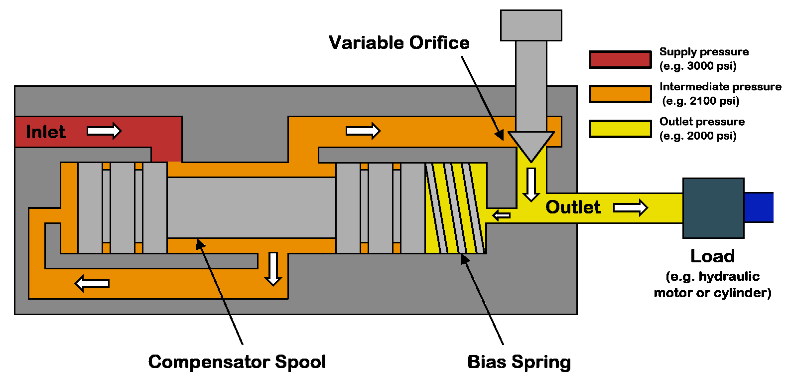
A pressure compensator works by comparing two pressure signals, one of which is a target and the other a pilot reading of downstream pressure. I’ve created a diagram showing a cutaway of a pressure compensated flow control and a symbol for the same (note, these valves are not identical). The primary difference between the two examples is the location of the compensator. The cutaway places the compensation before the variable orifice, while the symbol example places the compensator afterthe orifice. However, both will work so long as the compensator measures the pressure drop across the orifice.
Because flow rate is a function of pressure drop, and because pressure differential changes with flow rate, these understandings allow us to make sense of pressure compensator operation. Starting with the pressure compensated flow control symbol on the right, the flow path starts at port 1 and continues past port 3 out to the subcircuit being regulated.
The compensator has a spring value of 90 psi, and just like this example, most often, the spring value comes fixed. The compensator spool uses two pilot passages to measure pressure drop across the needle valve. In this case, port b measures pressure upstream of the needle valve at port 1, while port a measures downstream pressure at port 2.
The compensator spool will open or close itself to maintain 90 psi of differential pressure across the needle valve. Should load-induced pressure increase at port 2, the yellow pilot path to port a will push the spool backwards to open the combined flow path from port 1 to port 3. Should downstream pressure again decrease or supply pressure upstream of port 1 increase, any differential pressure than 90 psi will push the valve closed to restrict flow.
The cutaway example works much the same way. The red inlet flow must first pass a metering notch before entering the orange chamber, where the flow accesses its input. Next, metered flow crosses from orange to yellow before exiting the valve at the top. The yellowpassage comprises the differential pressure to the tune of the spring (assume 90 psi once again) trapped by the magenta spool. The difference in pressure between the orange and yellow defines the pressure drop through the needle valve.
Should downstream load-induced pressure at yellow start to decrease pressure drop from orange to yellow, the magenta spool moves backwards to open the flow path from red to orange, thereby increasing flow to sustain 90 psi pressure drop. Conversely, should pump-side pressure increase upstream of red, the increased pressure in the orange chamber will close the magenta spool against the spring. With less flow entering the orange chamber, pressure drop from orange to yellow remains stable at 90 psi.
In many ways, a pressure compensator is both a pressure and flow valve, but really quite simple in operation. For more information on pressure compensators, watch the Lunchbox Session videos on the subject. Expertly narrated by Carl Dyke, the first in the series can be found here.
Another option is to utilize a load sense compensator. With a load sense compensator, this compensator will include a lighter spring setting to control the swash plate. Upstream pressure is ported into a load sense port on the pump, as the pressure requirement increases, the pressure acts against the load sense piston. Once the pressure requirement is higher than the offset, the pump swash plate angle changes and the pump begins to increase flow, by increasing the swash plate angle, until we have enough pressure to balance the piston. Once balanced, the flow remains steady until the load changes.
The offset pressure is normally 200-300 PSI. With a load sense compensator, the pump produces what the load requires plus the spring offset, normally 200-300 PSI.
This system will also utilize a standard compensator so if the system pressure increases enough, the pressure compensator will take control and reduce the swash plate angle to reduce the pressure.
With a standard pressure compensator, you would have to set the pump at 2600 PSI to accomplish the work. When the work only requires 1500 PSI, the pump will be trying to produce 2600 PSI. Fifty percent of the time, your system will be operating at 1100 PSI of inefficiency, which means heat. With a load sense compensator, when the load requires 1500 PSI, the pump will actually produce about 17-1800 PSI. Yes, this is 300 PSI inefficient, but that is much better than 1100 PSI inefficient.
With a varying load, the load sense is a much better system. For additional control, you can utilize an electronic proportional flow control or throttle. You can use an electrical signal to vary the hydraulic signal which is received by the pump’s load sense line. This would give you full electronic control of the amount of flow the pump produces.
There are additional control options which allow you to remotely control the pressure compensator. With this remote compensator control, you can set 2 or more different system pressures. With the ability of a variable piston pump to build 5,000 or more PSI; the additional setting can be used when operating components with a much lower pressure requirement.
The next control is a torque limiting or HP limiting control. By adding an additional spring and piston, you can set a pump to always maximize its allowable input torque, therefore, maximizing output flow and pressure at a defined setting.
In this application, you are operating large bore, long strong cylinder. The cylinder has a 10” bore and 150” stroke. During most of the stroke, the cylinder is not doing very much work and can operate at 800-1200 PSI. During the last 20” of stroke, we want to hit our system pressure of 4500 PSI, but we can move much slower.
Our pump has an output of 15 CIR, a maximum flow of about 113 gallons at 1750 RPM. Our prime mover is an electric motor, 75HP with a 1.15 service factor. I want to keep my cylinder moving as fast as possible, but I also want to ensure that I never exceed a power demand 82 HP.
At 82 HP, the pump can produce 1254 PSI at full output, 113 GPM. As the load requires more pressure, the pump will begin to reduce flow and increase pressure. At 90 GPM flow, the system will produce about 1560 PSI; at 60 GPM we can get almost 2350 PSI. At 4500 PSI, the pump flow will be reduced to about 31 GPM. The advantage of this pump is that the internal controls of the pump are adjusting to maximize flow and pressure at all times without exceeding the available HP.
If I wanted to use a pump which could produce 113 gallons of flow at 4500 PSI, I would need 296 HP. If I choose a 75 HP motor with a pressure compensated variable piston pump, the motor would stall before the pressure compensator could kick in and reduce the pump flow. Depending on the load, a load sense pump could also stall the 75 HP motor if the load pressure is high enough to use up the HP before the pressure compensator kicks in. With a torque limiting (HP) control, we utilize the full limits of the prime mover and maximize power usage.

Pressure compensated hydraulic systems are becoming more popular due to their high efficiencies. These systems run great when properly applied but there are things you should know before you run a pressure compensated system.
Heat and contamination are the two leading causes of failure in a hydraulic system; if both aren’t properly maintained then your system will inevitably fail. For now, let’s focus on the heat. Heat can be a hard culprit to chase down when starting a prototype system. Two major factors of heat generation in a pressure compensated system are relief valve heat and standby heat.
When first starting up a pressure compensated hydraulic system, you have to always set the pressures on the pump’s compensator and the main system relief valve. Doing this properly is the key to avoiding heat generation. The compensator must always be set at a lower pressure than your system relief valve. If the system relief is lower or equal to the compensator setting, you will have constant flow over the main relief, which will then produce a ton of heat until the system fails. It is a safe practice to set your system relief valve 300 PSI above what your compensator is set at. This will ensure no flow is going over the relief during normal working conditions but will still protect your systems from any pressure spikes.
A cause of heat that is rarely considered – and to some, completely unknown – is the standby heat. The benefit of a pressure compensated pump is that it will destroke once the pressure builds to the compensator setting, therefore cutting off the pump flow but still maintaining the desired pressure. The downfall to this is that if you are running at a high pressure and are destroked at the compensator pressure, you are creating heat inside the case which will flow out of the case drain line and into your reservoir. Many may think of this as a minor amount of heat, but if a system is left sitting in this high-pressure standby state, the heat can become a major factor in your system. Below is a chart that shows just how much heat can be created at different pressures and speeds when sitting at compensator pressure.

422 hydraulic pump compensator products are offered for sale by suppliers on Alibaba.comAbout 48% % of these are hydraulic pumps, 6%% are pumps, and 3%% are construction machinery parts.
A wide variety of hydraulic pump compensator options are available to you, You can also choose from piston pump, gear pump and vane pump hydraulic pump compensator,as well as from 1 year, 6 months, and 3 months hydraulic pump compensator,and whether hydraulic pump compensator is hydraulic power units, or valves.


 8613371530291