
pressure compensated hydraulic pump free sample

In the example, a 10 GPM pressure compensating pump is supplying fluid through a hand valve to a hydraulic motor. The pressure required to drive the motor is 800 PSI. The pump compensator is set at 1000 PSI. With the hand valve fully open, all 10 GPM can flow to the hydraulic motor. The pressure on both sides of the hand valve is basically the same since the motor is the only resistance in the circuit. The compensator spool does not shift because the system pressure is below the compensator setting
In the next example, the hand valve is partially closed off. Only 7 GPM can flow through the valve and to the motor. Pressure will now build upstream of the hand valve because 10 GPM cannot flow through the valve. When the pressure nears 1000 PSI, the compensator spool shifts, allowing the pump volume to be reduced. The pump now only supplies 7 GPM to the system.
In the next operation the hand valve has been fully closed. The pump will now fully de-stroke and deliver nearly 0 GPM. Only enough fluid will be supplied to make up for bypassing in the pump and system.
Bypassing will be at maximum when the pump is compensating. Heat is generated as the small amount of bypassed fluid returns to tank. A cooler installed in the case drain will remove this heat.
When the pump compensates, the GPM drops down near zero so therefore the horsepower required to drive the pump also drops. The electric motor doesn’t pull as much current to drive the system, therefore conserving energy.

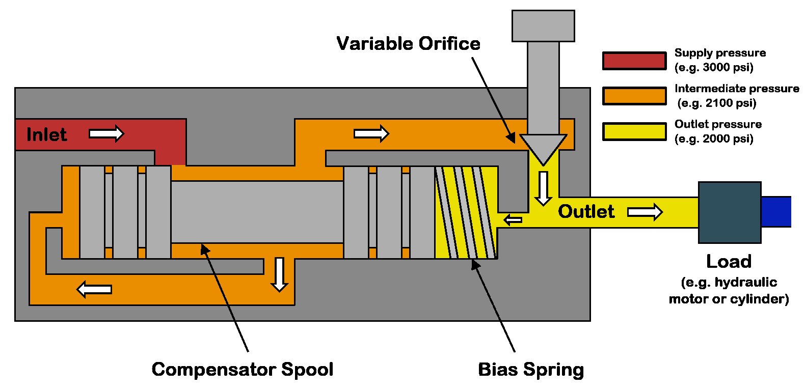
A pressure compensator is a device built into some pumps for the purpose of automatically reducing (or stopping) pump flow if system pressure sensed on the pump outlet port, should rise above a pre-set desired maximum pressure (sometimes called the "firing" pressure). The compensator prevents the pump from being overloaded if an overload is placed on the hydraulic system.
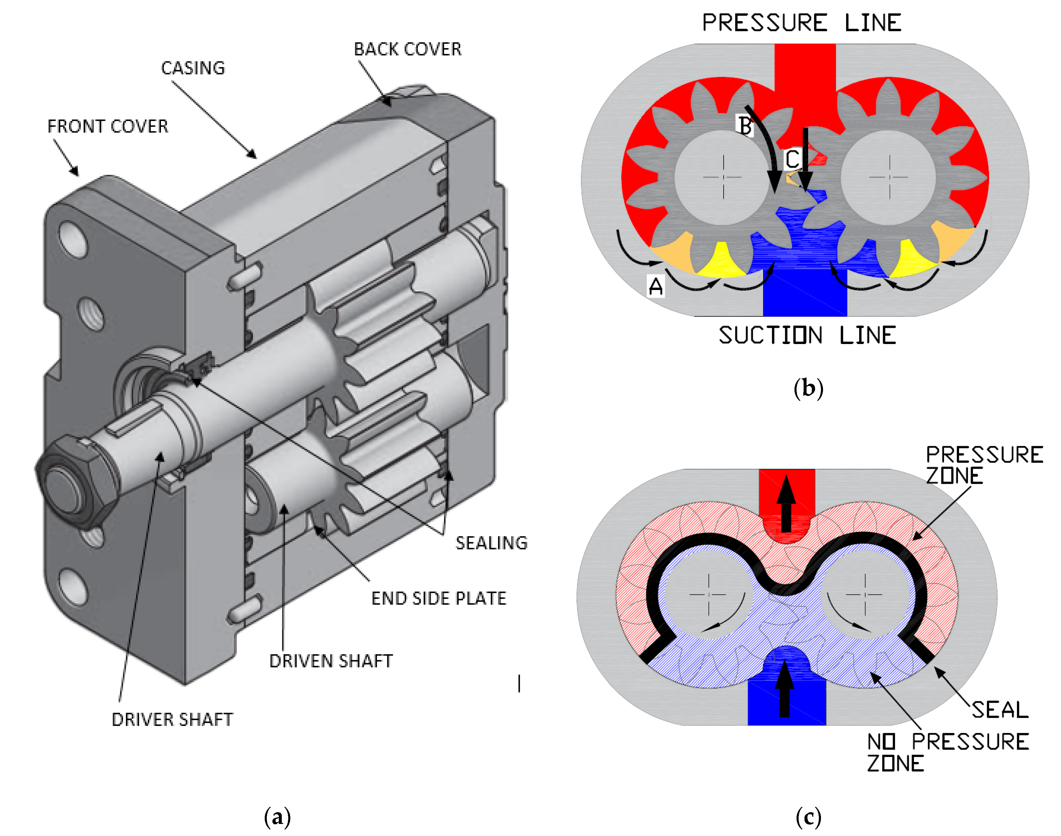
A compensator is built into the pump at the factory and usually cannot be added in the field. Any pump built with variable displacement can be controlled with a compensator. These include several types of axial piston pumps and unbalanced (single lobe) vane pumps. Radial piston pumps can sometimes be built with variable displacement but do not lend themselves readily to this action. Most other positive displacement pumps including internal and external gear, balanced (double lobe) vane, gerotor, and screw types cannot be built with variable displacement.
Figure 1 is a schematic of a check valve axial piston pump, variable displacement, controlled with a pressure compensator. The pistons, usually 5, 7, or 9 in number, are stroking inside a piston block which is keyed to and is rotating with the shaft. The left ends of the pistons are attached through swivel joints, to piston shoes which bear against and slide around on the swash plate as the piston block rotates. The swash plate itself does not rotate; it is mounted on a pair of trunnions so it can swivel from neutral (vertical) position to a maximum tilt angle. The angle which the swash plate makes to the vertical causes the pistons to stroke, the length of stroke being proportional to the angle. Normally, at low system pressures, the swash plate remains at its maximum angle, held there by spring force, hydraulic pressure, or by the dynamics of pump construction, and pump flow remains at maximum. The compensator acts by hydraulic pressure obtained internally from the pump outlet port. When pump pressure rises high enough to over-come the adjustable spring behind the compensator piston, the "firing" pressure has been reached, and the compensator piston starts to pull the swash plate back toward neutral, reducing pump displacement and output flow. The spring in the compensator can be adjusted for the desired maximum or "firing" pressure.
Under working conditions, on a moderate system overload, the compensator piston reduces the swash plate angle just enough to prevent the system pressure from exceeding the "firing" pressure adjusted on the compensator. On severe overloads the compensator may swing the swash plate back to neutral (vertical) to reduce pump flow to zero.
Maximum Displacement Stops. Some pumps are available with internal stops to limit the tilt angle of the swash plate. These stops limit the maximum flow and limit the HP consumption of the pump. They may be fixed stops, factory installed and inaccessible from the outside, or they may be externally adjustable with a wrench.
Manual Control Lever. Some pressure compensated pumps, especially hydrostatic transmission pumps, are provided with an external control lever to enable the operator to vary the swash plate angle (and flow) from zero to maximum. On these pumps the pressure compensator is arranged to override the manual lever and to automatically reduce the swash plate angle if a system overload should occur even though the operator control lever is still shifted to maximum displacement position.
Basically the pressure compensator is designed to unload the pump when system pressure reaches the maximum design pressure. When the pump is unloaded in this way, there is little HP consumed and little heat generated even though pressure remains at the maximum level, because there is no flow from the pump.
Variable displacement pumps are usually more expensive than fixed displacement types, but are especially useful in systems where several branch circuits are to be supplied from one pump, and where full pressure may be required simultaneously in more than one branch, and where the pump must be unloaded when none of the branches is ill operation. If individual 4-way valves are used in each branch, each valve must have a closed center spool. The inlet ports on all 4-way valves must be connected in parallel across the pump line. However, if all branch circuits are operated from a bank valve of the parallel type, a pressure compensated variable displacement pump may not be necessary; a fixed displacement pump, gear, vane, or piston, may serve equally well because the bank valve will unload the pump when all valve handles are placed in neutral, but when two or more handles are simultaneously shifted, their branch circuits will automatically be placed in a parallel connection.
As in all hydraulic systems, more pump oil will flow to the branch with the lightest load. Bank valve handles can be modulated to equalize the flow to each branch. When individual 4-way valves are used in each branch, flow control valves may be installed in the branch circuits and adjusted to give the flow desired in each branch.
Figure 2 shows a multiple branch circuit in which a variable displacement pump is used to advantage. Individual 4-way valves, solenoid operated, are used for each branch, and they have closed center porting. Please refer to Design Data Sheet 54 for possible drift problems on a pressure manifold system. A pressure relief valve is usually required even with a pressure compensated pump due to the time interval required for the swash plate to reduce its tilt angle when a sudden overload occurs. The relief valve will help absorb part of the pressure spike generated during this brief interval. It should be adjusted to crack at about 500 PSI higher than the pressure adjustment of the compensator piston spring to prevent oil discharge across it during normal operation.
All hydrostatic transmission systems use a variable displacement pump with pressure compensator, and often combine the compensator with other controls such as the horsepower input limiter, load sensing, flow sensing, or constant flow control.

Pressure compensation is the control of flow by compensating for the changes in load pressure. Most hydraulic systems today use pre-compensation as a means of maintaining consistent flow from an orifice or spool. However, there are applications when post-compensation has advantages over pre-compensation.
The fundamental difference is that with pre-compensation, the pressure drop across the orifice or spools is determined by the compensator. With post-compensation, the pressure drop is determined by the load sense (LS) spring inside the pump.
In post-compensated systems with multiple functions, the pump flow is divided at a fixed ratio. If flow settings exceed the pump output capability, the flow is reduced to each function at a fixed ratio. This is why post-compensation is sometimes referred to as “flow sharing”.
In post-compensated circuits, the pressure drop across each valve is determined by the load sense spring in the pump and all valves or orifices will have the same pressure drop. The load sense differential, sometimes referred to as standby, decreases when the pump cannot satisfy the total demand. All pressure compensators reference the highest load of the various functions.
The benefits include high efficiency under partial load and/or partial speed conditions and all functions slow down together at a fixed ratio when the pump cannot fully satisfy demand.
In the example below, the pump differential, or standby, is 200 PSI. The load sense pump will develop enough pressure to overcome the load and maintain a 200 PSI differential. The pressure drop across the valve or orifice remains fixed and is calculated by: system pressure minus the highest load pressure minus the compensator spring value.
The circuit below is an example of the flow sharing aspect. When another function is operated and the pump cannot fully satisfy the flow demand, the differential decreases. The pressure drop across each valve or orifice is reduced at the same fixed ratio, so the flow is divided, or shared, equally. In this example, each valve is fully open so total pump flow is shared equally between the functions.
So what happens when the functions require different flows and the pump cannot fully satisfy the total flow demand? The pump flow will be divided into the ratio of each function to total flow available. In the example below, the theoretical total flow demand is 42 GPM. The ratio of the function flow demand to total theoretical flow demand multiplied by the maximum pump flow is the resulting actual flow from each valve.
Post-compensation will increase stability and control in systems where demand can exceed the pump’s flow output. Because of its increased efficiency under partial load conditions, the compensator saves horsepower and reduces heat. It will also make the initial movement of actuators more predictable and provide better operator control.

We usually think and practice corresponding for the change of circumstance, and grow up. We aim at the achievement of a richer mind and body as well as the living for Mini 12v Dc Hydraulic Power Pack Unit, Dc Hydraulic Power Unit, Small Hydraulic Power Unit, Created products with brand value. We attend seriously to produce and behave with integrity, and by the favor of customers at home and abroad in the xxx industry.
This power unit specially designs for stackers. It’s made up of high pressure gear pump, AC motor, multi- manifold, hydraulic valve, oil tank, etc. There’s micro switch on manual unloading valve. The lift and fall action of stacker is controlled by joy sticker of unloading valve. Fall speed is automatically controlled by built-in pressure compensated throttle valve.
It adheres for the tenet "Honest, industrious, enterprising, innovative" to develop new products and solutions continuously. It regards shoppers, success as its individual success. Let us produce prosperous future hand in hand for Free sample for Komatsu Hydraulic Gear Pump - Power Unit for Semi-electric Stacker – Guorui, The product will supply to all over the world, such as: Slovakia, Sri Lanka, Slovakia, In the increasingly competitive market, With sincere service high quality products and well-deserved reputation, we always offer customers support on products and techniques to achieve long-term cooperation. Living by quality, development by credit is our eternal pursuit, We firmly believe that after your visit we will become long-term partners.

The following is an unedited transcript from a recent Fluid Power World Webinar:Load Sense Hydraulics Simplified. FPW Associate Editor Mike Santora moderates with the presenter, Carl Dyke.
Mike Santora: Hello and thank you, everyone, for attending today’s webinar, Load Sense Hydraulics Simplifiedbrought to you by Fluid Power World magazine, Ametek, and Higginson. We would like to thank our presenter, Carl Dyke, for being here today. I’m Mike Santora Associate Editor for Fluid Power World Magazine and I’ll be your moderator.
Ametek Factory Automation has been supplying linear displacement transducers to the hydraulics industry for more than 30 years, under the brand name Gemco. The technology they use to help solve cylinder positioning needs is called magnetostriction. Magnetostriction transducers are the preferred feedback in hydraulic cylinders. They are absolute and can survive conditions associated with hydraulic cylinders. Whether it is high temperature, pressure or high cycle rate, there’s simply nothing to wear out. Ametek transducers are known for their flawless operation in the most demanding and hostile environments.
Load sense hydraulic is a deep topic to try and cover inside of a one-hour session. There are so many design and engineering perimeters for manufacturers of machinery that integrate a load sense type of system. In this particular webinar, we’re going to try and stick to the basics and illustrate them as best we can for practical purposes.
A load sense system, if you think about the typical pressure compensated pump, the type of pump that might only have three hoses, the type of pump that has a high-pressure cutoff only, that’s the type of pump that can match the flow demand that occurs as you open a throttling valve, a proportional directional valve. But as we’re going to find out, a load sense system adds a fourth hose, a control hose to that pump. It allows the pump also to match the pressure needs and the pressure demands. We’re going to find out more about that as we go.
CD:All right, well I hope that your opportunity to fly through a load sense system in 3D helps a little bit with what is the sometimes slightly dryer, more obscure terminology that goes with load sense systems. Why is a load sense system so attractive? Primarily because of the opportunity to save input energy, which also translates in so many circumstances into a reduction of heat, but how is that done? Well, for a moment, let’s go backward to a time of simpler hydraulic systems, systems that are still in place for some simpler machinery, consider the gear pump and the relief valve.
A gear pump is always pumping at its maximum flow. If we’re using a proportional valve to meter the flow rate to an actuator, then we’re always operating this hydraulic system at maximum energy consumption. What you see here on a cut-away model with the gear pump and a relief valve, you will also see that the proportional valve is only set to half open in order to control speed as desired to the cylinder. Well, if that’s the case, our gear pump is pumping at full volume, of course, but also we are pumping over the relief valve, the unused fluid that is not desired at the cylinder. Therefore, we’re also pumping at maximum pressure.
The energy consumption is what you see by the horsepower line, which is the dark blue diagonal, all the way across the red zone. That’s a picture of our input energy. Well right now, we’re running with an enormous amount of input energy where, at the business end of the hydraulic system over there on the right past the hydraulic cylinder, we can see the energy requirement for flow and pressure at the cylinder is actually quite low. The horsepower line in green shows energy, or the horsepower output that we actually need to move the load; so a very inefficient system. I think you get the picture there.
Then, enter the pressure compensated pump, the type of pump that has only one setting, a high-pressure cutoff point. Well, in this type of system, this pump still operates at its maximum pressure. It’s matching the flow output to the demand at the proportional valve, but we’re still operating at maximum pressure. This is still a lot better than the gear pump. Gear pumps in some systems aren’t more than 10% energy efficient, where the pressure compensated pump arrangement can possibly make it possible to get to 25% energy efficiency.
Here we see an energy picture for the pressure compensated pump. What we can see that’s changed is while the flow rates of the pump now matches the demand through the proportional valve, we see that we’re still pumping at maximum pressure, but at least that diagonal dark blue line is now shorter by at least a percentage, and those energy savings are welcomed; both from in terms of cost of input energy, and potential for building up undesirable heat in the system.
As we bring in the load sense pump, which has an additional compensator, some manufacturers refer to that second adjustment as the flow compensator. But I think really what you saw in the video, and what you’ll see as we continue here, is that, that flow compensator, that load sense adjustment is just another pressure compensator with a softer spring setting. We also bring in pressure feedback on a special signal line, as we’ll see in the next screen, that ties in from the load at the cylinder. What we’re really doing is we’re setting pressure compensation on the fly. There’s a big energy savings potential associated with that.
In this image here, that thinner, narrower, yellow horizontal line you see it going from the proportional valve back to the pump’s compensator controller, that’s our load sense signal line. That’s our opportunity to instruct the pump about what’s happening at the load in the cylinder. We could have that load sense signal line coming right from the cylinder, but it’s generally more convenient to have it pick up either the A or the B work port lines from the cylinder just inside the directional valve, as shown here.
Here’s our energy savings curve when we look at where the big potential is for energy savings and heat reduction in a load sense system. What we’re seeing now is that this system not only matches the flow rate requirement, the pressure compensated pump did that. But the load sense system is also matching the pressure issues, the pressure requirements in the hydraulic cylinder, and producing a pump outlet pressure that’s only slightly higher than what’s needed at any one time. Look how short that diagonal dark blue line is now. There is the big savings. The opportunity here to go from pressure compensated pump systems, which might reach 25% energy efficiency, right up to potentially 60% energy efficiency for a load sense system. My source on that statistic came from a parker, a pump division manual that I was looking at to verify yesterday; and just refresh on that.
If you imagine for a moment that I click on the green plus button, which very gently just adds one brick to the stack on top of the cylinder; which then might perhaps increase our load pressure from 900 PSI, that’s the gauge on the right, up to 1200 PSI as we add that one brick. That pressure value is transmitted along the load sense signal line up the yellow vertical and across horizontally to the left to the pump’s controller; where that 1200 PSI would be added to the 300 PSI perhaps spring setting in the load sense compensator, to then change the left gauge reading before the flow … before the metering valve. Increasing that one to 1500 PSI, and thereby always maintaining a 300 PSI pressure drop as seen on the bottom gauge, our delta P gauge. The type of gauge that has two pressure inputs to it.
What we find out is that no matter what happens to our load at the cylinder, adding or removing bricks as a way of seeing pressure changes, our pump is constantly changing its maximum output pressure and holding a value that allows us to have steady flow through the flow controlling device without needing to work at very high pressures. Lots of energy savings there.
You might be thinking for a minute, what happens during shock load? Well yeah, that’s where things start to get a little bit more interesting. What happens if that third brick drops from the sky, let’s say, instead of being added gently? It hits down hard on the cylinder as its lifting up. Well, that might induce a pressure like what we’re showing on the right-hand gauge at the moment, 1500 PSI.
Well, if our left side gauge was still at 1200 PSI, the momentary pressure compensation value from the pump. Well, now we have a reverse delta B of negative 300 PSI. As you could imagine, for a very brief moment in time, this cylinder might grind to a halt as the new load sense pressure is transmitted to the pump, which can happen a little slowly. In some cases with shock pressure, there may be a shudder or a brief interruption in the cylinder’s motion, and enter in discussions about exactly where should the margin pressure be set on a load sense pump. Well, we’ll come back to that one in a moment.
Let’s go to the next level, one that we looked at in the video where things get most interesting. That is when we have a multifunction load sense system, where we’ve got more than one parallel application. In this case, enter in a very small little element inside the load sense system, often just a very small ball bearing, the shuttle valve; sometimes called ball resolvers. One in each section of a multi-section valve bank, and also pressure compensators in each valve section. Why are they needed?
Here is a schematic depiction of a simplified two section load sense system. On the left, you’ll see our blue return line through a cooler and filtration to tank. In the middle, we’ll see our load sense pump with its controlling compensator shown in full detail. Then over to the right, a two-section valve bank with, in each case, a hydraulic motor. We put some brake shoe brick stackers over top of those motor symbols so that we’ll be able to imagine different pressure loadings for each section.
Let’s zoom in a little bit and move that return to tank line off to the left. Now that we’re just looking at … the pump on the left, and the load sense capable two section valve crank on the right take a moment to notice down low in the middle, a line marked ‘LS.’ Leaving the valve bank in orange, and it is our load sense signal line transmitting up to port X on the pump compensator, top left. Also notice the common pump line in red entering in through the port marked ‘P’ on the lower left side of the valve bank, and moving along the bottom of the valve bank supplying two applications. Two valve sections in parallel.
The interesting features that we’re drawing some attention to here, and you saw them in 3D in the video as well in green. We see circled the load sense shuttle valves, the ball resolvers. You saw what tiny little parts those were in 3D in the video, and highlighted in purple, our pressure compensators, also very necessary. There’s a reminder of the components that we were talking about in the video.
Adjustment procedures is an area where things get kind of interesting. There’s some different terminology that can be applied here. I think one of the things that’s really important, I’m going to jump to the bottom bullet point first. That is to check with the manufacturer of your pump, or check with the manufacturer of your machine, and find out what they recommend as the best and safest procedure. Make sure you have training and guidance the first time that you’re making these adjustments to keep safe around potentially hazardous pressurized hydraulic systems.
Typically, that pressure compensator adjustment, that pressure cutoff, the one with the stiffer spring, that one will be adjusted first at the highest pressure. To make that adjustment, that may require that the load sense adjustment be tightened right down to the bottom so that it doesn’t react, or it might be recommended that the load sense signal line coming into that compensator be connected somehow to the pump’s main outlet during that first setting. Again, check with your pump manufacturer for that.
Then, the load sense adjustment is set to the required standby pressure, which is going to be a low value, often in the range of around 300 PSI. That’s the standby pressure that would be present on the main outlet of the pump when the system is in neutral; meaning that there’s really no consumption flow path through the machine, that the valve handles have been released. We’re in a neutral state.
Alternately, some manufacturers of machinery want the adjustment process to involve the measurement of pressure differential across a valve section from the inlet of the valve section to an outlet to, say, a hydraulic motor while oil is flowing. Those are the two typical procedures there. Again, we’re moving through this very briefly. It’s very difficult to cover all facets of load sense hydraulics inside of a one hour session, but hopefully this is giving you a sense of some key issues.
On the maintenance side of things and troubleshooting side, what we find in our travels is that the margin or standby pressure setting has to be set correctly. If it’s set too high, if we widen that red margin that you see there, that’s going to cause heating in the hydraulic system that wasn’t there before. That’s a waste of energy as well, which could be electricity or it could be diesel fuel. If it’s set too low, that may allow for some momentary stalling or shuddering in hydraulic cylinder action. For reasons tied to the example I was showing you earlier, where we had a shock loader, perhaps a sudden increase in pressure loading at the actuator.
In our travels over 20 years, so many problems that we end up helping to troubleshoot that tied back to contaminated flue, a flue that’s contaminated specifically with solid particles. What we haven’t shown in schematic form is that in many cases, … but I think you saw it in the video. In many cases, there is a damping orifice in the load sense signal line. The reason that orifice is often installed is so that momentary, very short lived changes in pressure loading at the hydraulic cylinder or motor, if they’re going to be very short lived changes in increases in pressure, we may not want to tell the pump’s compensator about those pressure changes; at least not tell the pump fully about them. Because by the time the pump may upstroke to react, the pressure loading at the cylinder may have gone away. We can end up into an osculation cycle where this is some unevenness in cylinder speed produced by the slow feedback that occurs as a pressure shockwave travels through the load sense signal line.
Quite often, there’s a load sense damping orifice, and that’s a very small opening. Again, doesn’t take much contaminants in there to now cause a slowdown at actuators when the work becomes harder. In other words, higher pressure.
Again with contaminated particle, contaminated fluid, a plugged bleed down orifice may be a problem. What’s the bleed down orifice? Well, all load sense systems typically have this. It’s either in the pump’s compensator, or if it’s not there, if you don’t find it in the pump’s compensator, the bleed down orifice might be in the load sense valve bank itself. Basically, why it has to be there is when you let go of the valve handles, when we say, ‘Hey, we don’t need our hydraulic cylinders or hydraulic motors to move for a period of time, that’s the time to really save input energy and allow the pump to idle down to that low standby pressure.’ If that bleed down orifice becomes plugged, then the pump’s outlet pressure may not drop down to that low standby pressure. We’ll be wasting input energy and building up unnecessary heat. …
Yes, the contaminated … again with particle contaminants, we have one example from this model of valve bank sitting in our shop where another component coming apart in the system had shed some aluminum particles. It caused the pressure compensator to become completely stuck and jammed in place. What happens in this case, if the pressure compensator can’t move, is that we’ll often see a speed up or slow down at the lower pressure actuators on the valve bank when the heavier loaded valve sections experience their pressure changes.
MS:Okay, thanks, Carl. Yeah, so we’re going to move on to some questions. The first we have coming in for you, Carl, is what is the most common load sense margin pressure value?
The physical size of the load sense line, in many respects, is actually quite large. Keep in mind that the load sense line is really not carrying any noticeable amount of flow. Yes, there is flow through the bleed down orifice when the valve handles are in neutral. There is a continuous flow, but it’s very, very small. The load sense signal line is really there just to transmit a pressure value, which can move as a shock wave through the fluid, whether it’s flowing or not.
MS: Okay, so here’s a question that I’ve actually had myself, because I hear both terms used. Is there a difference between margin pressure and standby pressure?
CD: In most cases, the answer to that is no. Certainly, the answer is no in terms of load sense system ideals. But there is the odd machine that we bump into where all of a sudden, there is a difference where the margin pressure may be referring to the setting of that softer spring, perhaps let’s say 300 PSI, that softer spring and the compensator. Due to the way the machine works when it’s running, or perhaps when the engine is at high idol, the machine manufacturer may have allowed for a signal higher than zero PSI to be transmitted back to the load sense compensator on the pump.
They may be allowing for a 50 or a 100 PSI signal to keep the system in a higher state of readiness for the valves when they open. In that case, we’ll see that the standby pressure, which you might measure on the pump’s outlet at that moment, might actually be 50 or 100 PSI higher than the margin pressure you set earlier, which was just the spring setting itself.
MS: Okay, Carl. I have another question I want to throw at you. It looks like somebody has asked is there a difference between post and pre-compensated valves?
CD: Oh yeah, okay. The pressure compensators in the valve banks themselves, I think is what’s being asked here. Yes, there is a bit of difference. There have been other webinars on that. We followed some other valve bank manufacturers. We’re not the designers or manufacturers of any valve banks, but yes, we do notice that some mobile machinery manufacturers choose to go with the pressure compensators directly on the A and B work ports as we’re traveling out to the hydraulic cylinders, as opposed to our example where the pressure compensator was coming in before the P port on the spool.
If I understand correctly and if my memory serves, I believe that in many cases, you get a more accurate … and faster acting compensation for extremes of changes in pressure loading at the cylinders when the pressure compensators are post spools. I think there’s a couple of arguments, couple of schools of thought there, and different valve bank manufacturers argue for the benefits of one versus the other.
If you’d like to access more information about an introduction to hydraulic pumps, we highly recommend that you visit LunchBox Sessions’ website and make use of the fabulous resources available there.
Some of the sessions are free; you don’t need to sign up. However, if you are serious about expanding your knowledge of hydraulic systems, we recommend you consider signing up for a subscription to the entire LunchBox Session service. This way, you get full access to all the interactive training materials, tests and simulations for just $29 per month. Students are entitled to a 60% discount off this price when they share their college or university ID.

Provisional application for patent No. 60/405,674 of Aug. 24, 2002 with the same title: “Equalizing Flow From Pressure Compensated Pumps, With or Without Load Sensing, in a Multiple Pump Circuit” which is hereby incorporated by reference. Applicant claims priority pursuant to 35 U.S.C. Par. 119 (e) (I).
This invention relates to improving the performance of two or more pressure compensated pumps, with or without load sensing, that supply fluid to a single driven circuit. The invention uses a rotary type flow divider operating in reverse to make fluid flow through the pumps at the same rate of flow even when the pumps are limited to different output pressures.
It is often necessary to use more than one pressure compensated pump, with or without load sensing, to supply a hydraulic circuit"s highest flow demand. A prior art hydraulic system might use separate pumps, with separate drive motors for each pump, to feed into a common manifold that supplies pressurized hydraulic fluid to a circuit. In such a prior art arrangement there is an attempt to set each pump so that they will operate at the same sensed pressure level such that when there is a need for pressurized flow that both pumps will supply at least part of the flow. The main problem with such a prior art arrangement is that no matter how closely the pumps are set, one pump will almost always start first and the other pump or pumps sensing the increased pressure will not operate. Even when it is possible to set the pumps to supply flow simultaneously, contamination, wear, spring deterioration and other variations will soon change such that one pump will start off supplying flow and the other pump or pumps will not start until the system requirements exceed the capacity of the first pump. The concept can be implemented with two or more pumps.
The prior art multiple pump system allows one pump to lead and the other pumps to start flowing when pressure drops due to a flow demand higher than the first pump can supply. One pump starts and the others start as needed. Some pump manufacturers recommend their pumps be set with triggering pressures 100–150 PSI apart so that they will not try to start flowing at the same time. The problem with starting the prior art system pumps at nearly the same pressure is that the first pump can be forced to no flow when the second pump flow reaches the manifold. In this situation the pumps can oscillate on and off so fast that they suffer mechanical damage.
Thus it can be seen that there is a need for a multi-pump system that will allow for multiple pumps to supply hydraulic fluid to a single hydraulic circuit.
A rotary flow divider is normally used to divide the flow from a single pump to two or more separate circuits. Operating in reverse of normal installation, the rotary flow divider can become a rotary flow combiner, combining two or more flows instead of dividing them. Normally hydraulic fluid from a pump is fed into a single inlet of a rotary flow divider, is ported to two or more identically sized hydraulic motors in the rotary flow divider and flows out two or more outlets to supply hydraulic fluid in equal volume to two or more circuits. The hydraulic motors of the rotary flow divider have a common shaft so they must turn at the same rate and since they are equal in size they pass the same flow. Equal flow leaving each hydraulic motor outlet of the rotary flow divider is sent to devices needing the same flow even though the devices may operate at different pressures.
In this invention the rotary flow divider"s normal outlets become inlets for the rotary flow combiner receiving flow from multiple pump sources and combines them into a common flow output. Since the hydraulic motors of the rotary flow combiner perform like pumps when driven it does not matter if the pressure compensating pumps with or without load sensing have exactly the same pressure setting. When the circuit needs flow the pressure drop at the rotary flow combiner outlet also gives a pressure drop at both inlets causing the pump compensators to shift both pumps on flow and to maintain them on flow. With both pumps flowing pressure at the outlet of the flow combiner equalizes.
In another aspect of the invention, when the system requires more fluid than the pumps are capable of producing, pressure drops below compensator setting of both pumps and they will go to full flow. If one pump has less flow than required to meet the demand it will see a vacuum at its outlet since the rotary flow combiner acts as a pump, at this point hydraulic fluid will be drawn directly from a reservoir to make up the required flow difference. This differential flow is powered by the pump with the larger flow through the rotary flow combiner.
FIG. 2 illustrates the operation of the preferred embodiment of the present invention when the embodiment is functioning with identical pumps at low pressure;
FIG. 3 illustrates the operation of the preferred embodiment of the present invention when the embodiment is operating with pumps of different flows at less than maximum pressure;
FIG. 4 illustrates the operation of the preferred embodiment of the present invention when the embodiment is operating with pumps of different flows near maximum pressure;
FIG. 5 illustrates the operation of the preferred embodiment of the present invention when the embodiment is operating with pumps at different pressures while an actuator is moving at a pressure higher than the low pressure pump can reach;
FIG. 1 illustrates the preferred embodiment of the present invention. As shown in FIG. 1 a hydraulic system 100 comprises two pressure compensated pumps 1A and 1B powered by drives 3 which can be electrical or can be internal combustion engines or a combination of one electrical motor and one engine. The system 100 supplies fluid power to any number of actuators such as fluid driven rotating actuators 12, 13 or a fluid driven linear actuator 14 in driven circuit 200. Three position solenoid controlled valves 8 can be used to control the operation of the rotating actuators 12, 13 and linear actuator 14 while the meter out flow controls 9 can set the flow requirements for each actuator 12, 13, 14. Filter 10 filters the flow of hydraulic fluid back to reservoir 6. Anti-cavitation check valves 5A and 5B, have 1 PSI springs in them so they can open and keep the rotary flow combiner 7 from starving for hydraulic fluid from a either pump 1A, 1B. Flow meters 2 can show the flow of each pump 1A, 1B and pressure gauges 24 and 25 can show pressure from the pumps 1A and 1B in supply lines 20 and 23. Pressure gauge 27 shows the pressure in line 26, which is the outlet of the rotary flow combiner 7 and the supply for the driven circuit 200.
FIG. 2 illustrates the hydraulic system 100 with the hydraulic motor 12 using, for example, 22 gallons per minute (GPM) flow as set by the meter out flow controls 9. The rotary flow combiner 7 accepts fluid from the first pump 1B that starts flowing and immediately the operation of the rotary flow combiner 7 will lower the pressure in line 23 enough to trip the pump 1A making it flow as well. Check valve 5A connected parallel to pump 1A, keeps the left rotary motor 7C of the rotary flow combiner from cavitating by allowing hydraulic fluid to flow to it from the reservoir 6 until pump 1A produces flow. Pressure on gauges 24, 25 and 26 will read at or near the same pressure (750 PSI) while the rotary motors 7C and 7D are running. Flow meters 2A and 2B will show identical flow when both pumps 1A and 1B are operating. Both pumps 1A and 1B will give equal flow until reaching set flow of meter out flow control 9, thus the system makes continual effective use of both pumps 1A and 1B.
Rotary flow dividers have a characteristic referred to as ‘intensification’ when used in the conventional manner. If there is resistance to flow out of one outlet of a rotary flow divider, then pressure in that outlet will intensify as the rotary flow divider will attempt to maintain the same volume of flow to each outlet. In this invention, with the rotary flow divider reversed to be a rotary flow combiner 7, fluid entering the inlets 7A and 7B is deintensified so if one pump 1A is at 1000 PSI and the other pump 1B is at 0 PSI, then the outlet line 26 will be at 500 PSI. (1000+0/2=500).
FIG. 3. Illustrates the hydraulic system 100 of the hydraulic motor actuator 12 using hydraulic fluid at a rate again of 22 GPM as set by meter out flow controls 9. In this arrangement of the driven circuit 200 the left pump 1A is set to pump no more than 8 GPM so anti-cavitation check valve 5A is forced open by atmospheric pressure which pushes an extra 3 GPM into line 23. The same result would occur if left pump were replaced with a pump only capable of producing 8 GPM flow. Because of the vacuum, gauge 25 will actually read a pressure slightly below zero such as −2 PSI. Pump 1B is at 11 GPM and 1200 PSI. Note that pump 1B is actually capable of pumping 15 GPM at 1500 PSI and that pump 1B provides the extra power that allows the rotary flow combiner 7 to pull additional hydraulic fluid through the check valve 5A. Since only one pump 1B is at pressure, hydraulic fluid going to the hydraulic motor actuator 12 is only at half pressure 600 PSI; (1200 psi+0 psi)/2=600 PSI. Flow meter 2A is showing 8 GPM while flow meter 2B is showing 11 GPM with the flow through the check valve 5A making up the rest of the 22 GPM flow.
FIG. 4 illustrates the hydraulic system 100 with said driven circuit 200 with the hydraulic motor actuator 12 still requiring hydraulic fluid at the same 22 GPM rate as set by meter out flow control 9. In this case the left pump 1A is only capable of pumping 8 GPM and the pressure required to operate the hydraulic motor actuator 12 is higher than half the set pressure of pump 1B. The pump 1B will go to full pressure and the flow from pump 1B will be reduced (a characteristic of pressure compensated pumps). When pump 1B flow has dropped to 8 GPM, flow from pump 1A will push into the left inlet 7A of the rotary flow combiner 7 at 500 PSI and the rotary flow combiner will push 16 GPM at 1000 PSI into the driven circuit 200. This flow is not enough to meet the full requirements of the driven circuit 200 but will keep the driven circuit 200 working. In all cases, flow into the inlets 7A and 7B of the rotary flow combiner 7 will be equal when any flow is present.
FIG. 5 illustrates the driven circuit 200 with the hydraulic motor actuator 12 still requiring hydraulic fluid at a rate of 22 GPM as set by meter out flow control 9. In this case the hydraulic motor actuator can use 22 GPM at a pressure above what the lowest pressure pump 1A or 1B can supply. The pump 1A can produce 15 GPM at 1300 PSI and the pump 1B can produce 15 GPM at 1500 PSI. The rotary flow combiner 7 in this case will produce output flow of hydraulic fluid to the driven circuit 200 at 22 GPM and 1400 PSI maximum and 15 GPM up to 1500 PSI. Again although pump 1A is not fully capable of meeting the load requirement both pumps will operate at capacity. Without a rotary flow combiner 7 this combination of pumps, with flows into a manifold, could only produce 15 GPM at pressures above 1300 PSI because the lower pressure pump 1A would compensate to no flow above this pressure.
FIG. 6 illustrates the driven circuit 200 with the hydraulic motor actuator 12 still requiring hydraulic fluid at a rate of 22 GPM as set by meter outflow controls 9. This hydraulic system 300 for example uses the same driven circuit 200 but uses three pressure compensated pumps without load sensing 1A, 1B and 1C that feed into the inlets 70A, 70B, 70C of a three motor rotary flow combiner 70. The operation of the three motor rotary flow combiner 70 is similar to that of the two motor rotary flow combiner 7 in that each rotary motor 70D, 70E and 70F must turn at the same speed and allow for the same flow rates from each inlet 70A, 70B and 70C regardless of flow or pressure settings. The rotary motors 70D, 70E and 70F can be gear motors for example sharing a common shaft (not shown) that keeps them rotating at a proportional rotary speed such as the same speed. Fluid from the third pump 1C is supplied through line 29 to inlet 70C and gauge 28 can monitor pressure in line 29.
Using a rotary flow combiner with motors having different ratio flows (not shown) would allow different flow rated pumps to use all their flow output at a pressure without restricting the higher flow ones.
A specific example of a useful application is when separate internal combustion engines are driving pumps of the same or different volumes at the same or different pressures. Each internal combustion engine would give its required portion of flow and operate at a comparable horsepower rating for any flow requirement. Without the equal flow provided by the rotary flow combiner, one engine would do all the work most of the time, while the other burns fuel and does no useful work. Neither engine would be operating efficiently. Adding the rotary flow combiner 7 as shown above causes both engines to do a significant portion of the work at all times resulting in even wear on the engines and in more efficient operation.
A benefit of this invention is that the pumps in a multi-pump system can be set as closely as possible to the same pressure without causing the pumps to override each other. An additional benefit of this invention is that a conventional multiple pressure compensated pump with or without load sensing circuit can have a noticeable pressure drop as the lead pump reaches its maximum flow and the next pump starts flowing. This pressure drop will be at least as much as the pumps pressures are set differently and even more for a short period of time as the lagging pump or pumps respond and start flowing.

Open vs. closed center hydraulic systems can be complex to understand. So let us explain the main differences between the two systems and the pros/ cons of application use.
In open center hydraulic systems oil flows through entire system continuously . A solenoid directs flow in the component to either operate the component (ex.- compressor or crane), or to bypass the component without operating it.
In closed center hydraulic system’s the main pump is pressure compensated, which means that the flow is directed to components only when needed. When a component is not in use, the system pressure flow does not flow through the component.
The most noticeable difference in open and closed center hydraulic systems will be the addition of a “load sense line” connection on the closed center version. This connection will send a hydraulic signal back to the pressure compensated pump when the compressor is needed.
Vanair® offers both open and closed center versions of all Reliant™ Air Compressors. Reliant compressors are hydraulically driven and offer 30 to 185 CFM of air power, these reciprocating and rotary screw machines outperform the competition by offering a wider range of air power. Ideal for a variety of heavy-duty markets, these vehicle-mounted designs carry many built-in features, including cold weather packages and integrated hydraulic/compressor oil coolers.
Check that the pump shaft is rotating. Even though coupling guards and C-face mounts can make this difficult to confirm, it is important to establish if your pump shaft is rotating. If it isn’t, this could be an indication of a more severe issue, and this should be investigated immediately.
Check the oil level. This one tends to be the more obvious check, as it is often one of the only factors inspected before the pump is changed. The oil level should be three inches above the pump suction. Otherwise, a vortex can form in the reservoir, allowing air into the pump.
What does the pump sound like when it is operating normally? Vane pumps generally are quieter than piston and gear pumps. If the pump has a high-pitched whining sound, it most likely is cavitating. If it has a knocking sound, like marbles rattling around, then aeration is the likely cause.
Cavitation is the formation and collapse of air cavities in the liquid. When the pump cannot get the total volume of oil it needs, cavitation occurs. Hydraulic oil contains approximately nine percent dissolved air. When the pump does not receive adequate oil volume at its suction port, high vacuum pressure occurs.
This dissolved air is pulled out of the oil on the suction side and then collapses or implodes on the pressure side. The implosions produce a very steady, high-pitched sound. As the air bubbles collapse, the inside of the pump is damaged.
While cavitation is a devastating development, with proper preventative maintenance practices and a quality monitoring system, early detection and deterrence remain attainable goals. UE System’s UltraTrak 850S CD pump cavitation sensor is a Smart Analog Sensor designed and optimized to detect cavitation on pumps earlier by measuring the ultrasound produced as cavitation starts to develop early-onset bubbles in the pump. By continuously monitoring the impact caused by cavitation, the system provides a simple, single value to trend and alert when cavitation is occurring.
The oil viscosity is too high. Low oil temperature increases the oil viscosity, making it harder for the oil to reach the pump. Most hydraulic systems should not be started with the oil any colder than 40°F and should not be put under load until the oil is at least 70°F.
Many reservoirs do not have heaters, particularly in the South. Even when heaters are available, they are often disconnected. While the damage may not be immediate, if a pump is continually started up when the oil is too cold, the pump will fail prematurely.
The suction filter or strainer is contaminated. A strainer is typically 74 or 149 microns in size and is used to keep “large” particles out of the pump. The strainer may be located inside or outside the reservoir. Strainers located inside the reservoir are out of sight and out of mind. Many times, maintenance personnel are not even aware that there is a strainer in the reservoir.
The suction strainer should be removed from the line or reservoir and cleaned a minimum of once a year. Years ago, a plant sought out help to troubleshoot a system that had already had five pumps changed within a single week. Upon closer inspection, it was discovered that the breather cap was missing, allowing dirty air to flow directly into the reservoir.
A check of the hydraulic schematic showed a strainer in the suction line inside the tank. When the strainer was removed, a shop rag was found wrapped around the screen mesh. Apparently, someone had used the rag to plug the breather cap opening, and it had then fallen into the tank. Contamination can come from a variety of different sources, so it pays to be vigilant and responsible with our practices and reliability measures.
The electric motor is driving the hydraulic pump at a speed that is higher than the pump’s rating. All pumps have a recommended maximum drive speed. If the speed is too high, a higher volume of oil will be needed at the suction port.
Due to the size of the suction port, adequate oil cannot fill the suction cavity in the pump, resulting in cavitation. Although this rarely happens, some pumps are rated at a maximum drive speed of 1,200 revolutions per minute (RPM), while others have a maximum speed of 3,600 RPM. The drive speed should be checked any time a pump is replaced with a different brand or model.
Every one of these devastating causes of cavitation threatens to cause major, irreversible damage to your equipment. Therefore, it’s not only critical to have proper, proactive practices in place, but also a monitoring system that can continuously protect your valuable assets, such as UE System’s UltraTrak 850S CD pump cavitation senor. These sensors regularly monitor the health of your pumps and alert you immediately if cavitation symptoms are present, allowing you to take corrective action before it’s too late.
Aeration is sometimes known as pseudo cavitation because air is entering the pump suction cavity. However, the causes of aeration are entirely different than that of cavitation. While cavitation pulls air out of the oil, aeration is the result of outside air entering the pump’s suction line.
Several factors can cause aeration, including an air leak in the suction line. This could be in the form of a loose connection, a cracked line, or an improper fitting seal. One method of finding the leak is to squirt oil around the suction line fittings. The fluid will be momentarily drawn into the suction line, and the knocking sound inside the pump will stop for a short period of time once the airflow path is found.
A bad shaft seal can also cause aeration if the system is supplied by one or more fixed displacement pumps. Oil that bypasses inside a fixed displacement pump is ported back to the suction port. If the shaft seal is worn or damaged, air can flow through the seal and into the pump’s suction cavity.
As mentioned previously, if the oil level is too low, oil can enter the suction line and flow into the pump. Therefore, always check the oil level with all cylinders in the retracted position.
If a new pump is installed and pressure will not build, the shaft may be rotating in the wrong direction. Some gear pumps can be rotated in either direction, but most have an arrow on the housing indicating the direction of rotation, as depicted in Figure 2.
Pump rotation should always be viewed from the shaft end. If the pump is rotated in the wrong direction, adequate fluid will not fill the suction port due to the pump’s internal design.
A fixed displacement pump delivers a constant volume of oil for a given shaft speed. A relief valve must be included downstream of the pump to limit the maximum pressure in the system.
After the visual and sound checks are made, the next step is to determine whether you have a volume or pressure problem. If the pressure will not build to the desired level, isolate the pump and relief valve from the system. This can be done by closing a valve, plugging the line downstream, or blocking the relief valve. If the pressure builds when this is done, there is a component downstream of the isolation point that is bypassing. If the pressure does not build up, the pump or relief valve is bad.
If the system is operating at a slower speed, a volume problem exists. Pumps wear over time, which results in less oil being delivered. While a flow meter can be installed in the pump’s outlet line, this is not always practical, as the proper fittings and adapters may not be available. To determine if the pump is badly worn and bypassing, first check the current to the electric motor. If possible, this test should be made when the pump is new to establish a reference. Electric motor horsepower is relative to the hydraulic horsepower required by the system.
For example, if a 50-GPM pump is used and the maximum pressure is 1,500 psi, a 50-hp motor will be required. If the pump is delivering less oil than when it was new, the current to drive the pump will drop. A 230-volt, 50-hp motor has an average full load rating of 130 amps. If the amperage is considerably lower, the pump is most likely bypassing and should be changed.
Figure 4.To isolate a fixed displacement pump and relief valve from the system, close a valve or plug the line downstream (left). If pressure builds, a component downstream of the isolation point is bypassing (right).
The most common type of variable displacement pump is the pressure-compensating design. The compensator setting limits the maximum pressure at the pump’s outlet port. The pump should be isolated as described for the fixed displacement pump.
If pressure does not build up, the relief valve or pump compensator may be bad. Prior to checking either component, perform the necessary lockout procedures and verify that the pressure at the outlet port is zero psi. The relief valve and compensator can then be taken apart and checked for contamination, wear, and broken springs.
Install a flow meter in the case drain line and check the flow rate. Most variable displacement pumps bypass one to three percent of the maximum pump volume through the case drain line. If the flow rate reaches 10 percent, the pump should be changed. Permanently installing a flow meter in the case drain line is an excellent reliability and troubleshooting tool.
Ensure the compensator is 200 psi above the maximum load pressure. If set too low, the compensator spool will shift and start reducing the pump volume when the system is calling for maximum volume.
Performing these recommended tests should help you make good decisions about the condition of your pumps or the cause of pump failures. If you change a pump, have a reason for changing it. Don’t just do it because you have a spare one in stock.
Conduct a reliability assessment on each of your hydraulic systems so when an issue occurs, you will have current pressure and temperature readings to consult.
Al Smiley is the president of GPM Hydraulic Consulting Inc., located in Monroe, Georgia. Since 1994, GPM has provided hydraulic training, consulting and reliability assessments to companies in t...

When you need to choose a hydraulic pump solution for a hydraulic system, it is important to decide what type of pump you will require. You must also understand the basics of how pumps work and hydraulics.
All hydraulic systems rely on pressurized fluid to create force in order to perform work that is accomplished by transforming mechanical energy into hydraulic energy inside hydraulic pumps and creating a positive displacement downstream. For example, a forklift needs to raise and lower pallets—which would be the desired work.
You must also choose between a ‘closed-loop’ or ‘open-loop’ system. In a ‘closed-loop’ system, the fluid passes from the pump directly to the motor before returning to the pump. In an ‘open-loop’ system, the pump draws the fluid from a reservoir or tank, and then pumps it to a control valve from where it is directed to the services being operated before returning to the tank.
Fixed-displacement pumps are well suited to a wide range of functions where the amount of pressure required to perform work is the same each and every time. For instance, if the pump is rated as a 30 cc pump, it will pump 30 ml of hydraulic fluid through the system for every single rotation.
The pressure and flow rate will not change, no matter how the pump is operated or what occurs elsewhere in the system. If you need a lower flow rate, then you will have to divert the excess flow or use a variable displacement pump.
Two common types of fixed-displacement pumps you can use are the bent axis piston pump and the gear pump. The bent axis piston pump provides the added benefit of normally having a higher pressure capability than a gear pump.
Aside from flow rates being directly proportional to pump drive speeds, fixed-displacement hydraulic pumps have several key benefits over variable displacement pumps, including:
Unlike fixed-displacement pumps, variable displacement pumps are able to increase or decrease the fluid flow rates electronically, manually, or hydraulically. The method used will depend on the flow required and the type of pump being used, such as a vane pump, axial piston pump, etc.
Furthermore, the method of displacement changes based on the pump’s internal structure. For example, a variable displacement piston pump is determined by the bore area of the pistons and the stroke length. The stroke length can vary to help regulate the flow rates as shaft rotation turns and moves the pistons inside the pump.
The control piston inside the pump also helps regular pressure and, essentially, functions as a relief valve. When pressure increases above the desired pressure compensator setting, the control piston moves outwards and slows the travel distance of the other pistons.
As can be seen, fixed-displacement pumps and variable displacement pumps have their own benefits, depending on your specific needs. For further assistance in choosing the right pump or for other hydraulic system solutions, please feel free to contact White House Products, Ltd. at +44 (0) 1475 742500 today!


 8613371530291