
pto hydraulic pump for planter free sample

�����HydraBoost is a closed center, pressure compensating system powered by a pto,� says Dan Symington, Command Hydraulics. �We can produce the higher pressure needed for down pressure and for other precision planting equipment, as well as for vacuum fans and more.�
����The company suggests that HydraBoost works with every tractor/planter combination on the market. It is available in multiple sizes, from 12 gpm to 40 gpm, and can be equipped with either 4 or 6 additional ports. Reservoir capacity ranges from 15 to 25 gal., depending on pump size. The kit also includes Command Hydraulics� PumpDoctor, designed initially for use with Case IH and Kinze planters.
�����PumpDoctor is an integral part of HydraBoost,� says Symington. �We also sell it by itself for use with other pto-powered hydraulic pumps. Anytime you put a pump directly on the pto, you tend to get vibration. Our double chain connection PumpDoctor cushions it.�
����The PumpDoctor is a support bracket that secures any pto pump directly to any tractor frame via a mounting plate. Without such a bracket, the pump hangs on the pto shaft. The weight causes excess vibration, shaft strain and warping or breakage. The PumpDoctor is available in 3 models for 16, 18 and 12-tooth sprockets.
����The tractor mounting plate is designed to match the exact bolt pattern for specific tractor models, ensuring a secure and tight fit. The PumpDoctor kit also includes sprockets, chain and hardware for mounting.
����Contact: FARM SHOW Followup, Command Hydraulics, 8095 215th St. W., Lakeville, Minn. 55044 (ph 952 890-6800; toll free 800 778-6200; sales@commandhydraulics.com; www.commandhydraulics.com).
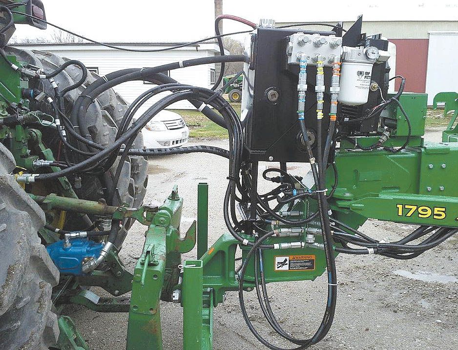
Slick Way To Add Extra Hydraulics MISCELLANEOUS EQUIPMENT Pumps You can get more hydraulic power from your existing tractor with HydraBoost from Command Hydraulics Designed to meet the needs of new planters and other hydraulic power hogs HydraBoost is a self-contained auxiliary hydraulic supply package It can eliminate the need to trade up tractors to run a planter that needs more hydraulic power �HydraBoost is a closed center pressure compensating system powered by a pto � says Dan Symington Command Hydraulics �We can produce the higher pressure needed for down pressure and for other precision planting equipment as well as for vacuum fans and more � The company suggests that HydraBoost works with every tractor/planter combination on the market It is available in multiple sizes from 12 gpm to 40 gpm and can be equipped with either 4 or 6 additional ports Reservoir capacity ranges from 15 to 25 gal depending on pump size The kit also includes Command Hydraulics� PumpDoctor designed initially for use with Case IH and Kinze planters �PumpDoctor is an integral part of HydraBoost � says Symington �We also sell it by itself for use with other pto-powered hydraulic pumps Anytime you put a pump directly on the pto you tend to get vibration Our double chain connection PumpDoctor cushions it � The PumpDoctor is a support bracket that secures any pto pump directly to any tractor frame via a mounting plate Without such a bracket the pump hangs on the pto shaft The weight causes excess vibration shaft strain and warping or breakage The PumpDoctor is available in 3 models for 16 18 and 12-tooth sprockets The tractor mounting plate is designed to match the exact bolt pattern for specific tractor models ensuring a secure and tight fit The PumpDoctor kit also includes sprockets chain and hardware for mounting HydraBoost ranges in price from $5 245 to $11 500 Pricing for the PumpDoctor is available from the company Contact: FARM SHOW Followup Command Hydraulics 8095 215th St W Lakeville Minn 55044 ph 952 890-6800; toll free 800 778-6200; sales@commandhydraulics com; www commandhydraulics com
It mounts easily to any planter and, depending which pump size is purchased, will provide an extra 12 gpm to 40 gpm as well as 4 to 6 additional ports.
Many producers wanting to upgrade or upsize their air seeders discover they are lacking hydraulic capacity on their current tractor, and don’t have room in their machinery budget to upgrade their tractor.
One solution is the Command HydraBoost PTO-driven auxiliary hydraulic system, these can operate a portion of the hydraulic flow requirement, allowing producers to continue using their favourite tractor! These units come in several sizes, the larger sizes - 24gpm, 32 gpm & 40 gpm are used in combination with air seeders.

This website is using a security service to protect itself from online attacks. The action you just performed triggered the security solution. There are several actions that could trigger this block including submitting a certain word or phrase, a SQL command or malformed data.
.jpg)
Table of ContentsIndexOperating, Maintenanceand Installation Instructions401-845A, 401-846A, 401-847A, 401-848A,401-849A, 401-879A and 401-956APTO Pump Accessory for Single-SectionAir-Pro ® Planters & Fan Update KitManufacturing, Inc.www.greatplainsmfg.comRead the installation manual entirely. When you see this symbol, thesubsequent instructions and warnings are serious - follow without exception.Your life and the lives of others depend on it!To avoid Injury orMachine Damage:*Operate only with540 rpm PTOCAUTION818-130C Rev. B34617Cover illustration shows only selected components for one kit. Manual illustrations mayshow various Yield-Pro ® planter models and configurations where installation detailsare identical for the immediate topic.ORIGINAL INSTRUCTIONSEN© Copyright 2013 Printed 2013-03-04 401-885MTable of ContentsIndex
Great Plains Manufacturing, Inc. Cover Index iiiTable of ContentsImportant Safety Information ......................................1PTO-Specific Hazards....................................................1Using PTO Safely...........................................................2Safety Decals .................................................................4Introduction ..................................................................6Description of Unit ..........................................................6Suitable Applications ..................................................6Document Family ...........................................................6Using This Manual..........................................................6Definitions...................................................................6Call-Outs ....................................................................6Owner Assistance ..........................................................7PTO Operation ..............................................................8Tractor Requirements.....................................................8PTO Clearance...........................................................8Hitching with PTO...........................................................9Prepare Tractor ..........................................................9Mount Pump ...............................................................9Secure Pump..............................................................9Check Hydraulics .........................................................10Check Oil Level ........................................................10Inspect Hoses and Fittings .......................................10Starting the Pump.........................................................11Setting Meter Pressurization ........................................12PTO Unhitching ............................................................13PTO Troubleshooting.................................................14PTO Maintenance .......................................................15Oil and Filter Change ...................................................15Oil Fill .......................................................................15Oil Specification....................................................15Oil and Filter Change................................................15Lubrication and Scheduled Maintenance .....................16Appendix A - Installation ...........................................17Before You Start...........................................................17Compatible Planters .....................................................17Fan Motor Compatibility............................................17Configuration Compatibility.......................................18YP425A Compatible Kits ..........................................18YP625A Compatible Kits ..........................................18YP825A Compatible Kits ..........................................18Other Single-Section Air-Pro ® Implements ..............18Tools Required .............................................................19Call-Outs ..................................................................19Pre-Delivery and Other Options................................... 19Prepare Planter............................................................ 19Prepare Fan ................................................................. 20Disconnect Existing Fan Hoses ............................... 20Disconnect 2-Port Fan ......................................... 20Disconnect 3-Port Fan ......................................... 20Open Fan Screen..................................................... 21Dismount or Relocate Sensor Bracket ..................... 21Update Fan Motor .................................................... 22Recover Motor Fittings ......................................... 22Release Impeller .................................................. 22Dismount Fan....................................................... 23Remove 3-Port Hydraulic Motor........................... 23Mount 2-Port Hydraulic Motor .............................. 24Re-Mount Fan ...................................................... 24Install New Impeller Bushing................................ 25Install Motor Fittings and Loop ............................. 26Re-Mount Fan Inlet Screen .................................. 26Re-Install RPM Sensor Bracket ........................... 27Install Fan Cooler......................................................... 27Install Fan Cooler ..................................................... 28Break Down Cooler Assembly ............................. 28Install Cooler Shroud............................................ 28Orient Cooler Elbows ........................................... 28Re-Assemble Fan Cooler..................................... 29Modify Fan Cage.................................................. 29Attach Cooler Hoses & Close............................... 30Reconnect Hitch Hoses ............................................... 31Install Oil Reservoir...................................................... 31Determine Reservoir Location.................................. 31Reservoir on Row Unit Tool Bar............................... 32Row Location ....................................................... 32Support Row Unit ................................................. 33Mount Row Unit Reservoir ................................... 33Reservoir on Fertilizer Sub-Frame............................... 34Reservoir on Mainframe Truss..................................... 35Install Flow Control Valve ............................................ 36Determine Control Location ..................................... 36Install Controls on Fan Mast .................................... 36Install Controls on Fertilizer Frame .......................... 37Install Hoses ................................................................ 38General Hose Installation......................................... 38401-845A Flow Control Hydraulics........................... 38401-846A Flow Control Hydraulics........................... 39401-847A Flow Control Hydraulics........................... 40401-848A Flow Control Hydraulics........................... 41© Copyright 2013 All rights ReservedGreat Plains Manufacturing, Inc. provides this publication “as is” without warranty of any kind, either expressed or implied. While every precaution has beentaken in the preparation of this manual, Great Plains Manufacturing, Inc. assumes no responsibility for errors or omissions. Neither is any liability assumed fordamages resulting from the use of the information contained herein. Great Plains Manufacturing, Inc. reserves the right to revise and improve its products asit sees fit. This publication describes the state of this product at the time of its publication, and may not reflect the product in the future.Trademarks of Great Plains Manufacturing, Inc. include: Singulator Plus, Swath Command, Terra-Tine.Registered Trademarks of Great Plains Manufacturing, Inc. include:Air-Pro, Clear-Shot, Discovator, Great Plains, Land Pride, MeterCone, Nutri-Pro, Seed-Lok, Solid Stand,Terra-Guard, Turbo-Chisel, Turbo-Chopper, Turbo Max, Turbo-Till, Ultra-Till, Verti-Till, Whirlfilter, Yield-Pro.Brand and Product Names that appear and are owned by others are trademarks of their respective owners.Printed in the United States of America2013-03-04 Cover Index 401-885M
2 Air-Pro ® PTO Pump Table of Contents Index Great Plains Manufacturing, Inc.Using PTO SafelyThe accessories covered by this manual rely on PTOpower to operate, and require an adjustment at theplanter while the PTO is running. The PTO pump isdesigned to work on a stub shaft PTO, and leaves noexposed shaft in use.▲ Use only a tractor with an approved master shield for thePTO.▲ Use all guards provide for the tractor PTO. Have minimalor NO shaft exposed after connecting the PTO pump.▲ Use only a rear-facing PTO. The provided hoses and torquearms are not designed for use with a tractor-front ortractor-side PTO.▲ Use only a 540 rpm PTO, or an adjustable PTO set to540 rpm maximum. Running at a higher speed could resultin equipment failure, and serious injury.▲ Use only a PTO with the correct shaft:1 3 ⁄ 8 inch (35 mm) 6-spline.▲ Do not use an adaptor, extender or external gearbox.▲ Use only a “live” or “independent” PTO. If the PTO onlyoperates when the tractor is in motion, there is no safe wayto set the fan speed.▲ Ensure that all involved personnel are trained on PTOoperations and hazards. Always know where all teammembers are before, during and after PTO operations.▲ Allow only essential personnel near the PTO during setup,adjustment, operation and disconnection.▲ Prior to PTO setup, remove any stray wire, rope or twinefound nearby. Should a loose end encounter the PTO stub, itis taken up at over 7 feet per second, and could wraparound someone and pull them in.▲ Wear only snug-fitting clothes, with no scarfs, loose strings,cords or ties, and no frays, when working near a PTO.▲ Tie long hair back or gather it up under a well-secured hat.▲ Always shut the tractor off when making PTO connectionsor disconnections. Do not trust your life to clutches andthrow-outs.▲ A PTO shaft is a hazard at any speed, even when well belowrated shaft rpm, coasting to a stop, or idling.▲ Never step on or over the master shield or installed PTOpump.▲ Be extra vigilant if any tractor PTO controls are external,and in proximity to the PTO.▲ Elevate pump hose slack so that ground contact is notpossible during transport or field operations.▲ Keep all PTO safety decals clean and legible. Replace anythat are faded or damaged.CAUTIONTo avoid Injury orMachine Damage:*Operate only with540 rpm PTO818-130C Rev. B✔1.375 in35 mm401-885M Table of Contents Index 2013-03-04
Great Plains Manufacturing, Inc. Table of Contents Index Important Safety Information 3Prepare for Emergencies▲ Be prepared if a fire starts▲ Keep a first aid kit and fire extinguisher handy.▲ Keep emergency numbers for doctor, ambulance, hospitaland fire department near phone.Be Familiar with Safety Decals▲ Read and understand “Safety Decals” in the Operatormanual.▲ Read all instructions noted on the decals.▲ Keep decals clean. Replace damaged, faded and illegibledecals.Avoid High Pressure FluidsObserve normal precautions for hitch hydraulicconnections and disconnections. Escaping fluid underpressure can penetrate the skin, causing serious injury.▲ Avoid the hazard by relieving pressure before disconnectinghydraulic lines.▲ Wear protective gloves and safety glasses or goggles whenworking with hydraulic systems.▲ If an accident occurs, seek immediate medical assistancefrom a physician familiar with this type of injury.Practice Safe Maintenance▲ Understand procedure before doing work. Use propertools and equipment. Refer to this manual for additionalinformation.▲ Work in a clean, dry area.▲ Lower the planter, put tractor in park, turn off engine, andremove key before performing maintenance.▲ Make sure all moving parts have stopped and all systempressure is relieved.▲ Inspect all parts. Make sure parts are in good conditionand installed properly.▲ Remove buildup of grease, oil or debris.▲ Remove all tools and unused parts from planter beforeoperation.2013-03-04 Table of Contents Index 401-885M
4 Air-Pro ® PTO Pump Table of Contents Index Great Plains Manufacturing, Inc.Safety At All Times▲ Thoroughly read and understand the instructions in thismanual before operation. Read all instructions noted on thesafety decals.▲ Be familiar with all implement functions.▲ Operate machinery from the driver’s seat only.▲ Do not leave implement unattended with tractor enginerunning.▲ Wear snug-fitting clothing to avoid entanglement withmoving parts.Safety DecalsSafety DecalsKit components are shipped with all safety decals inplace. They are intended to help you safely operate yourimplement.▲ Read and follow decal directions.▲ Keep all safety decals clean and legible.▲ Replace all damaged or missing decals. Order new decalsfrom your Great Plains dealer. Refer to this section forproper decal placement.▲ When ordering new parts or components, also requestcorresponding safety decals.Danger Decals858-005CDANGERTo install new decals:1. Clean the area on which the decal is to be placed.2. Peel backing from decal. Press firmly on surface,being careful not to cause air bubbles under decal.ROTATING DRIVELINE -CONTACT CAN CAUSE DEATHKEEP AWAY!DO NOT OPERATE WITHOUT-All driveline guards, tractorand equipment shields in placePTO pump assembly securelyattached with torque arm and chain858-005CDanger: Rotating DrivelineOn chain plate of torque arm at pump;1 totalCAUTION818-130C Rev. BTo avoid Injury orMachine Damage:*Operate only with540 rpm PTO34617401-885M Table of Contents Index 2013-03-04
858-004CGreat Plains Manufacturing, Inc. Table of Contents Index Important Safety Information 5Warning Decals858-004CWARNINGHOT FLUID HAZARDRead Owner’s Manual BEFORE operating machine.Keep tractor at IDLING SPEED and slowly engage PTOto prevent damage to Hydraulic MotorKeep Radiator clean and free of foreign matter toprevent overheating.Do NOT operate with hydraulic oil at or above 180°F.Warning: Hot FluidOn front face of oil reservoir;1 total34617CAUTION818-130C Rev. BTo avoid Injury orMachine Damage:0rpm PTO*Operate only withCaution Decals818-130CCAUTIONTo avoid Injury orMachine Damage:*Operate only with540 rpm PTO818-130C Rev. BCaution: 540 RPM PTOOn chain plate of torque arm at pump;1 totalCAUTION818-130C Rev. BTo avoid Injury orMachine Damage:*Operate only with540 rpm PTO346172013-03-04 Table of Contents Index 401-885M
6 Air-Pro ® PTO Pump Table of Contents Index Great Plains Manufacturing, Inc.IntroductionDescription of UnitOne of six dealer- or field-installed kits convert thehydraulic fan power source from tractor hydraulic remoteto tractor Power Take-Off (PTO). An additional kitupdates older fan motors for PTO compatibility.Refer to Figure 1Each Air-Pro ® PTO Pump kit includes:• a flow control valve assembly 1 for setting fan rpm,• a tethered 540 rpm PTO pump 2 , with torque arm andsafety chain (no gearbox or coupler is required),• an oil reservoir 3 , with sight gauge, line filter and6.5 gallon capacity (5.5 gallons/21 liters, used),• an oil cooler 4 , mounted inside the fan, and;• all interconnecting hoses (not shown).There are separate kits for pull-type and 3-point planters,and for planters with and without fertilizer capability.Suitable ApplicationsA PTO kit may be needed where:• the tractor has an Open Center hydraulic system;• the tractor has no remote port for the fan; or,• the tractor is Closed Center, but the remotes offerinsufficient oil flow to reliably operate the fan.Document Family401-885M Operation, Maintenance and Installation(this document)401-651M Operator manual, YP425A, YP625A andYP825A pull-type models.401-651B Rate manual, YP4/6/825A/3P401-652P Parts manual, YP4/6/825A pull-type401-652M Operator manual, YP425A3P, YP625A3Pand YP825A3P three-point models.401-652P Parts manual, YP4/6/825A 3-pointUsing This ManualThis manual familiarizes you with safety, operation,adjustments, maintenance and assembly. Follow therecommendations to ensure safe and efficient operation.DefinitionsThe following terms are used throughout this manual.RFUDBLCAUTION818-130C Rev. BTo avoid Injury orMachine Damage:*Operate only with540 rpm PTONote: Paragraphs in this format provide usefulinformation related to the current topic.2Liability, Economic and Results Risks:Paragraphs in this format present a crucial point of informationrelated to the current topic. Read and follow the directions to:remain safe, avoid serious damage to equipment and ensuredesired field results.Right-hand and left-hand asused in this manual areUdetermined by facing thedirection the machine will F Rtravel while in use unlessotherwise stated.LAn orientation rose (shown atright) depicts Up, Right, Back,Down, Left and Front.DBCall-Outs1 to 9 Single-character callouts identifyand components in the currently referenceda to z Figure or Figures. Numbers and letters maybe reused for different items on other pages.The information in this manual is current at printing.Some parts may change to assure top performance.3Figure 1:PTO Kit Major Components1434617401-885M Table of Contents Index 2013-03-04
Great Plains Manufacturing, Inc. Table of Contents Index Introduction 7Owner AssistanceIf you need customer service or repair parts, contact aGreat Plains dealer. They have trained personnel, repairparts and equipment specially designed for Great Plainsproducts. Your machine’s parts were specially designedand should only be replaced with Great Plains parts.Record your Air-Pro ® PTO pump kit model number herefor quick reference:Model Number:__________________________Date Purchased: __________________________Your Great Plains dealer wants you to be satisfied withyour updated machine. If you do not understand any partof this manual or are not satisfied with the servicereceived, please take the following actions.1. Discuss the matter with your dealership servicemanager. Make sure they are aware of anyproblems so they can assist you.2. If you are still unsatisfied, seek out the owner orgeneral manager of the dealership.For further assistance write to:Product SupportGreat Plains Mfg. Inc., Service DepartmentPO Box 5060 Salina, KS 67402-5060785-823-32762013-03-04 Table of Contents Index 401-885M
8 Air-Pro ® PTO Pump Table of Contents Index Great Plains Manufacturing, Inc.PTO OperationTractor RequirementsThe Air-Pro ® PTO pump accessories require a tractorwith:Refer to Figure 2• a rear-facing ASABE or ASAE Type 1 PTO stubshaft 5 with master shieldshaft: 1 3 6⁄ 8 inch (35 mm) 6-spline,clockwise rotation (as viewed from tractor rear, facingforward)• a “live” or “independent” PTO drive system, that canbe operated with the tractor stationary,• a fixed or available shaft speed of 540 rpm, and anavailable PTO power output of 5 hp (3.7 kW)• a drawbar 7 that engages the torque arm of the PTOpump assembly, and• a chain anchor point 8 - a stable, non-movingcomponent of the tractor, within reach of the pump’storque arm chain.CAUTIONTo avoid Injury orMachine Damage:*Operate only with540 rpm PTO818-130C Rev. BPTO ClearanceIf the tractor PTO is not known to conform to Type 1specifications, check the following pump-specificclearance dimensions:Refer to Figure 3a. Shaft to master shield top:3.5 inches (8.9 cm) minimumor hinged lidb. Shaft to master shield sides:5.0 inches (12.7 cm) minimumc. Shaft to drawbar top:9 inches (22.8 cm) minimum15 inches (38.1 cm) maximumIt may be necessary to invert an offset drawbar, orrelocate or remove any clevis installed on thedrawbar.d. Shaft to ground:16 inches (40.6 cm) minimumb8Figure 2:Tractor PTOacFigure 3:Tractor PTO Clearances657d3461834623401-885M Table of Contents Index 2013-03-04
Great Plains Manufacturing, Inc. Table of Contents Index PTO Operation 9Hitching with PTOThe pump may be installed before or after hitching theplanter to the tractor. With a 3-point planter, installing thepump first may be easier.Prepare Tractor1. Back the tractor into close proximity to the planter(within pump hose reach of the PTO shaft).2. Shut down the tractor and remove the key.2Entanglement and Crushing Hazard:Never perform any mechanical adjustment, PTO setup orhitching with the tractor running. Take no chances that thePTO might become active. Entanglement or flailing equipmentcan cause serious injury or death faster than you can react.Refer to Figure 43. Make any necessary adjustment to the tractordrawbar 1 . This might include:inverting an offset drawbar, and/orrelocating a clevis assembly (not shown).1Figure 4:Mount PTO Pump334620Entanglement and Flailing Equipment Hazards:Do not use a driveline, shaft extension, adaptor or externalgearbox with the PTO pump. Use the pump only on a native540 rpm 6-spline stub shaft. Extra fittings create entanglementhazards. Fittings also destabilize the shaft, and may make itimpossible to adequately secure the pump against torque andshaft slip.Mount Pump4. Clear the PTO shaft 2 of any pins or wires thatmight prevent the pump from fully seating on theshaft.5. With hydraulics hoses to rear, and torque arm 3 toright of drawbar, slide the pump assembly fully ontothe PTO shaft.Secure PumpRefer to Figure 5 (shown with pump off for clarity)6. With the torque arm firmly against the drawbar:loop the chain once 4 around the drawbar,then through the anchor point 5 ,then around the drawbar 1 at least once more,then through the keyhole slot 7 in the torque plate.The drawbar loops prevent pump rotation.The anchor loop retains the pump on the PTO shaft.5 467Figure 5:Route Pump Chain346222013-03-04 Table of Contents Index 401-885M
858-003C858-004C10 Air-Pro ® PTO Pump Table of Contents Index Great Plains Manufacturing, Inc.Refer to Figure 67. At least one full chain link must be exposed at theslot 7 on the decal side of the torque arm plate.If there are more than a few chain loops left at theplate keyhole, route any excess chain through theanchor point and/or around the drawbar.8. Do NOT use any pins, cross-bolts or wires to securethe pump to the PTO shaft. Such fasteners are notrequired for safe pump operation, and would add aneedless entanglement hazard.9. Pull and twist the pump assembly to verify that thechain is sufficiently taut to prevent excess pumprotation or sliding along the PTO shaft.10. Complete normal planter hitching.Check Hydraulics7DANGERROTATING DRIVELINE -CONTACT CAN CAUSE DEATHKEEP AWAY!DO NOT OPERATE WITHOUT-All driveline guards, tractorand equipment shields in placePTO pump assembly securely858-005Cattached with torque arm and chainCheck Oil LevelRefer to Figure 71. Verify that the planter is level front to back and sideto side.Figure 6:Secure Pump Chain346272. Inspect the sight gauge 8 on the pump systemreservoir tank. The oil level 9 must be aligned withthe center border of the OIL FILL LINE decal(858-003C).Hot Surface and Hot Fluid Hazards:Assess the tank temperature before adjusting oil level.Draining excess hot oil could result in a severe burn. If thePTO has been operated recently, the oil temperature could beas high as 180°F (82°C).3. Add or drain oil as needed to obtain the correctamount. Some adjustment is normally required witha new system, or after a filter change.Note: The fill level dimension from tank bottom is:a 9.15 inches (23.2 cm)If the 858-003C decal requires replacement, adjustthe center border line to this height.9a8OIL FILL LINECAPACITY = 5.5 U.S. GALSUSE ANY HIGH QUALITY MINERAL BASEDHYDRAULIC FLUID WITH A VISCOSITY RATINGOF 10W-30. OIL MUST BE CLEAN AND FREEFROM DIRT OR CONTAMINANT PARTICLES TOPREVENT DAMAGE TO PUMP AND MOTOR.REPLACE FILTER ELEMENT AFTER EVERY150 OPERATING HOURS OR 2 YEARS SERVICE.LEVEL TOOLBAR BEFORE CHECKING OIL LEVELWARNINGHOT FLUID HAZARDRead Owner’s Manual BEFORE operating machine.Keep tractor at IDLING SPEED and slowly engage PTOto prevent damage to Hydraulic MotorKeep Radiator clean and free of foreign matter toprevent overheating.Do NOT operate with hydraulic oil at or above 180°F.Inspect Hoses and Fittings4. Check that all hydraulic fittings are tight and dry.Inspect all hoses for damage, wear and fatigue.Because the PTO pump system is closed, anyvisible fluid may be an indication of a leak.Figure 7:Check Oil Level34625401-885M Table of Contents Index 2013-03-04
Great Plains Manufacturing, Inc. Table of Contents Index PTO Operation 11Starting the PumpWhile the planter is stationary, it may be necessary tobriefly operate the pump for any of several reasons:• verify system installation or PTO operation• verify oil level with system fully charged• set initial meter pressurizationRefer to Figure 81. If the system is adjusted, leave the flow controlvalve as-is.21If the system is not yet adjusted, close the flowcontrol valve to prevent fan motion. Turn the lockdisc 1 counter-clockwise to release the knob 2 .Turn the knob fully clockwise to close the valve.2. Clear the hitch area of non-essential persons.Check essential personnel for long hair, scarfs,cords, frays, loose flaps and anything else thatmight get entangled. Clear the area of dangling orloose wires, straps, cord and other lines that mightbecome entangled and pull someone in.3. It is not necessary to run the PTO at the full540 rpm. You may run it any speed that providessufficient meter pressurization (page 12).Figure 8:Flow Control ValveEntanglement and Crushing Hazard:Use extreme caution in the hitch area when the PTO isoperating.34626Equipment Damage Risk:Do not START the pump and fan suddenly at high PTO power.Engage the PTO clutch slowly (if possible) and/or at lowengine rpm, and gradually increase PTO rpm. The hydraulicfan can be damaged by sudden acceleration.4. • Check that tractor is in Park or Neutral.• Check parking brake set.• Set the tractor PTO controls for540 rpm gearing (if multi-speed) andclockwise rotation (if bidirectional).• Start tractor engine and set throttle to idle.• Engage the PTO.• Bring the tractor engine and PTO up to intendedfield rpms.5. Check for hydraulic fluid leaks.6. Verify fluid level in tank (page 10).High Pressure Fluid Hazard:Watch for signs of fluid leaks. Escaping fluid under pressurecan have sufficient pressure to penetrate the skin causingserious injury. Use a piece of paper or cardboard, NOT BODYPARTS, to check for leaks. Wear protective gloves and safetyglasses or goggles when working with hydraulic systems. If anaccident occurs, seek immediate medical attention from aphysician familiar with this type of injury.2013-03-04 Table of Contents Index 401-885M
12 Air-Pro ® PTO Pump Table of Contents Index Great Plains Manufacturing, Inc.Setting Meter PressurizationRefer to Figure 9Meter pressurization is set as for a standard planter,using the PTO kit valve 1 rather than a lever for a tractorhydraulic remote. This adjustment is normally made withthe seed meters full of seed.Consult your planter Seed Rate manual for the correctseed disk, meter inlet shutter setting, and recommendedinitial pressure as reported by the Magnehelic ® gauge 2 .1. Check that the Inlet Butterfly valve handle 3 is setto 30°. If not, loosen the pivot bolt, reset handle, andRe-secure bolt.2. Mount the PTO pump (page 9).3. Per your planter Operator manual, hitch the planter.Raise the planter. Install lift locks. This is to free themeter ground drive wheel.4. Shut off the tractor and remove the key.5. Consult your planter Seed Rate manual for theintended crop, noting:• Range and Transmission sprockets required,• correct Air-Pro ® seed disk (not shown),• initial inlet shutter setting (not shown), and• initial meter pressurization.6. Configure the meter drive system sprockets.7. Install seed disks. Leave rain covers off meters (notshown).8. Set meter inlet shutters per the Seed Rate manual.9. Open any slide gates under hoppers (not shown).10. Load enough seed to completely fill the meter inlettubes, and at least partially fill every hopper.11. Set out containers, under row unit seed tubes, tocollect seed metered during setup.12. Clear the hitch area of non-essential persons. Clearthe hitch area of non-essential persons. Checkessential personnel for long hair, scarfs, cords,frays, loose flaps and anything else that might getentangled. Clear the area of dangling or loosewires, straps, cord and other lines that mightbecome entangled and pull someone in.13. • Check that tractor is in Park or Neutral.• Check parking brake set.• Set the tractor PTO controls for540 rpm gearing (if multi-speed) andclockwise rotation (if bidirectional).• Start tractor engine and set throttle to idle.• Engage the PTO.• Bring the tractor engine and PTO up to intendedfield rpms.142Figure 9:Meter Pressure AdjustmentEntanglement and Crushing Hazard:Use extreme caution in the hitch area when the PTO isoperating.29842251373462614. At the flow control valve, turn the lock disc 4counter-clockwise to release the knob 1 . Slowlyturn the knob counter-clockwise to start the fan.Bring the fan speed up until the Magnehelic ® gaugedisplays the suggested pressure for this crop.15. Turn the meter ground drive wheel forward severalturns, until all exposed cells in all seed disks containseed.16. Recheck the Magnehelic ® gauge. The reportedpressure is likely to have increased. Adjust the flowcontrol knob to bring the pressure reading back tothe recommended value. Tighten the lock disc.17. Shut down the PTO, and as desired, the tractor.18. Install rain covers on seed meters.The PTO pump is now ready for field work. Someadjustment of meter pressure and inlet shutters may berequired, depending on seed and planting conditions.Use the flow control valve, and not the butterfly valve, tomake pressure adjustments.3401-885M Table of Contents Index 2013-03-04
Great Plains Manufacturing, Inc. Table of Contents Index PTO Operation 13PTO UnhitchingThe pump may be dismounted before or after unhitchingthe planter and tractor. With a 3-point planter,dismounting the pump last may be easier, which is theorder shown on this page. For safety, have the tractorcompletely shut down during PTO dismounting.1. At the tractor, shut down the PTO.Note: The PTO may be shut down suddenly or gradually.The fan circuit includes a bypass to recirculateexcess pressure during deceleration. The fan isonly sensitive to sudden acceleration.2. Do not approach the hitch area until the PTO shaft,and the fan, have slowed to a complete stop.3. Mechanically unhitch the planter per the Operatormanual. Leave the PTO pump mounted at this time.4. Pull the tractor forward enough to allow access tothe PTO pump. Put the tractor in Park or Neutral.Engage the parking brake. Shut the tractor down.Remove the key.5. Pass the free end of the pump chain forwardthrough the torque arm keyhole.6. Unwrap the chain from the anchor point anddrawbar.7. Slide the PTO pump off the PTO shaft. Store thepump on the planter. Use the chain to secure it toany available structure.Entanglement Hazard:Remain clear of a rotating PTO shaft. Even when coasting to astop, a PTO shaft can have enough residual torque to inflictserious or fatal injury.Hot Surface Hazard:Remain clear of the pump reservoir during unhitching.The oil may be hot enough to inflict a painful burn.2013-03-04 Table of Contents Index 401-885M
14 Air-Pro ® PTO Pump Table of Contents Index Great Plains Manufacturing, Inc.PTO TroubleshootingSymptom Cause RemedySeed meter pressuretoo lowPressure correct onMagnehelic ® , butskips or doublesFlow control adjusted too low Increase flow control (page 12).Fan butterfly valve closed or set at too high Reduce to 30° (page 12).an anglePTO rpm too lowBring up PTO rpm, but do not exceed540 rpm.Fan running in reverse (multiple possible See “Fan running in reverse” below.causes)Pump cavitating Check oil level (page 10).No blank disks in unused seed meters Install blank disks to balance pressure.Seed inlet shutters open too wideVerify setting vs., rate charts. Adjust asneed for actual seed pool.Oil filter clogged Replace oil filter and oil (page 15).Magnehelic ® gauge disconnected or Check air gauging system.sample line(s) leakingMagnehelic ® gauge uncalibratedRe-zero (see Operator manual).Flow control valve failure or malfunction Repair or replace valve.Fan seals damagedRepair or replace fan motor.PTO rotation and fan or valve hosesreversed (highly unlikely)Fan cooler pluggedPressure gauge disconnected or sampleline(s) leaking.Magnehelic ® gauge uncalibrated.Seed variety may require adjustment.Set tractor controls for clockwise PTO.Reconnect hoses.Clean or replace fan cooler.Check air gauging system.Re-zero (see Operator manual).Check all other possible pressure errors,then fine tune pressure for one seed perdisk cell.Oil overheating Oil filter clogged Replace oil filter and oil (page 15).PTO rpm too highAdjust system for ideal pressure at lowerPTO rpm.Fan running inreverseFan butterfly valve angle too high Reduce to 30° (page 12).PTO shaft turning counter-clockwise Set tractor controls for clockwise PTO.Hoses reversedCheck hose routing from pump to valve, totank and fan per Parts manual.Fan doesn’t run at all Low oil level in tank Top off tank. Check system for leaks.Flow control valve closed Adjust valve (page 12).Hoses misconnected Review installation (page 38).401-885M Table of Contents Index 2013-03-04
858- 03C858- 04CGreat Plains Manufacturing, Inc. Table of Contents Index 15PTO MaintenanceOil and Filter ChangeOil FillRefer to Figure 10 and Figure 11A dry or fully drained system may require as much as6.5 gallons (25 liters) of oil to charge the cooler, pump,motor, hoses, filter and valve, and leave 5.5 gallons(21 liters) in the reservoir.Before adding oil, check that the drain plug 1 is secure,and that there are no signs of leaks in hoses or at anysystem fittings.Oil Specification10W-30 good quality mineral base hydraulic fluid,viscosity 70 to 250 SUS at 210°F (100°C)Remove the filler cap 2 . Add oil until the oil level in thetank, as observed on the sight gauge 3 , reaches the fillline on the decal (the horizontal mid-border of the decal).The fill line is 9.15 inches (23.2 cm) above the tankbottom. If the 858-003C decal requires replacement,adjust the center border line to this height.Operate the PTO system briefly, or until the tank levelstops changing. See “PTO Operation” on page 8 foroperations.Recheck the sight gauge. As necessary, add oil to fillline.Oil and Filter ChangeAt a regularly scheduled oil change, also change thefilter. At initial system flush, no filter change is required.Refer to Figure 11 and Figure 101. Wait for the oil to cool before changing the oil.2. Place a container with at least a 7 gallon (26 liter)capacity under the drain plug 1 of the reservoir.3. Carefully remove the drain plug.4. Allow several minutes for oil in the filter to drain intoand out of the reservoir. Change filter as required.See page 16 for filter size. Seat filter perinstructions on filter.5. Thread the plug back into the tank. Seating torqueis 27 to 43 foot-pounds (37 to 58 N-m).32CAUTION818-130C Rev. BTo avoid Injury orMachine Damage:*Operate only with540 rpm PTOFigure 10:Oil Filler Cap and Filter34617Hot Surface and Hot Fluid Hazards:Assess the tank temperature before adjusting oil level.Draining excess hot oil could result in a severe burn. If thePTO has been operated recently, the oil temperature could beas high as 180°F (82°C).1OIL FILL LINECAPACITY = 5.5 U.S. GALSUSE ANY HIGH QUALITY MINERAL BASEDHYDRAULIC FLUID WITH A VISCOSITY RATINGOF 10W-30. OIL MUST BE CLEAN AND FREEFROM DIRT OR CONTAMINANT PARTICLES TOPREVENT DAMAGE TO PUMP AND MOTOR.REPLACE FILTER ELEMENT AFTER EVERY150 OPERATING HOURS OR 2 YEARS SERVICE.LEVEL TOOLBAR BEFORE CHECKING OIL LEVELWARNINGHOT FLUID HAZARDRead Owner’s Manual BEFORE operating machine.Keep tractor at IDLING SPEED and slowly engage PTOto prevent damage to Hydraulic MotorKeep Radiator clean and free of foreign matter toprevent overheating.Do NOT operate with hydraulic oil at or above 180°F.Figure 11:Oil Drain Plug346882013-03-04 Table of Contents Index 401-885M
16 Air-Pro ® PTO Pump Table of Contents Index Great Plains Manufacturing, Inc.Lubrication and Scheduled MaintenanceMulti-purposespray lubricantMulti-purposegrease lubricantMulti-purposeoil lubricant34208Inspection50Intervals(operating hours)at which serviceis requiredOil Filter25 / 1501 filter per planterType: Great Plains 891-110CFleetguard HF6610Pall HC 9540S UJ4HZinga HE-10Change filter after first 25 hours, and then every 2 yearsor 150 hours.orUTION34617Pump/Fan Oil300 or 4 Years1 tank per planterType: 10W-30 Mineral-Based Oil70 to 250 SUS at 210°F (100°C)Quantity: 5.5 U.S. gallons (21 liters)Change filter when changing oil, except at initial systemflush.orUTION34617Seal Kit1 kit per planterType: Great Plains 810-904CPrince PMCK-PTO-1A60034634Consult the PTO Series Pump Parts Manual, availablefrom Prince Manufacturing Corp:www.princehyd.com401-885M Table of Contents Index 2013-03-04
Great Plains Manufacturing, Inc. Table of Contents Index 17Appendix A - InstallationBefore You StartMost accidents are the result of negligence andcarelessness, usually caused by failure of the installer tofollow simple but necessary safety precautions. Allow noone to install the Air-Pro ® PTO pump before carefullyreading this manual.Fasteners may be loosely assembled. Remove thembefore mounting the component. Due to evolvingmanufacturing practices, sub-assemblies may already becompletely pre-assembled. If so, check that fasteners aretight, and skip the unneeded assembly steps.Compatible PlantersOne PTO pump kit is always required. Older plantersmay also require a fan update kit.Fan Motor CompatibilityThe Air-Pro ® PTO Pump kits require a 2-port fanhydraulic motor (having no case drain). Older planters,having 3-port fan hydraulic motors (with a case drain)cannot install a PTO kit unless the fan is updated.Check the planter serial number, or inspect the fan.Planters manufactured with 3-port fans are:3Planter ModelYP425AYP425A3PYP625AYP625A3PYP825AYP825A3PSerial Number or LowerB1008NB1004MB1043QB1006PB1014SB1007RIf the planter has a 3-port/case-drain fan motor, orderone fan update kit:KitPart NumberYP4,6,8 FAN UPDATE 401-956AInstructions for installing this kit are merged with theinstructions for the Air-Pro ® PTO Pump kits.B PortA Port2Figure 12:Top: Older 3-Port Fan MotorBottom: Current 2-Port Motor29781317542013-03-04 Table of Contents Index 401-885M
18 Air-Pro ® PTO Pump Table of Contents Index Great Plains Manufacturing, Inc.Configuration CompatibilityRefer to Figure 13 to distinguish between the liquid and dryfertilizer options.Before installing any kit, inspect the planter configurationand serial number plate (for precise model number).Refer to the Operator manual for plate location.Each kit updates one planter.YP425A Compatible KitsPTO Pump KitYP425A PlantersYP425A (PT) Dry Fertilizers/n B1005M+YP425A (PT) Liquid FertilizerYP425A (PT) without FertilizerYP425A3PYP625A Compatible Kits401-845A401-846A401-847A401-848A✔✔✔✔PTO Pump KitYP625A PlantersYP625A (PT) Dry FertilizerYP625A (PT) Liquid FertilizerYP625A (PT) without FertilizerYP625A3PYP625PDYP625TDYP825A Compatible KitsYP825A PlantersYP825A (PT) Dry FertilizerYP825A (PT) Liquid FertilizerYP825A (PT) without FertilizerYP825A3PYP825AR401-845A401-846A401-847A401-849A✔✔✔✔n/an/aPTO Pump Kit401-845A401-846A401-847A401-849A401-879A✔✔✔n aw bn/aa. For narrow row spacings: 30 inch (76.2 cm) or less.b. For “wide” row spacings: 36 inch (91.4 cm) or more.Figure 13:Top: Liquid Fertilizer PlanterBottom: Dry Fertilizer Planter2990931794Other Single-Section Air-Pro ® ImplementsPTO Pump Kit2025A2525AYP625PDYP625TDYP925TDPlanters Model401-845A401-846A401-847A401-848An/an/an/an/an/a401-849A401-879A401-885M Table of Contents Index 2013-03-04
Great Plains Manufacturing, Inc. Table of Contents Index Appendix A - Installation 19Tools Required• a lift or hoist with a 100 pound \ 45 kg capacity(600 pound \ 272 kg capacity for kits 401-845A,401-847A, 401-847A and 401-848A)• basic hand tools• 6 to 12 gallons of good quality 10-W30 mineral basehydraulic fluid, viscosity from 70-250 SUS range at210°F (100°C).• bucket for collecting oil• hose marker, such as white electrical tape andindelible marker• power equipment with a Type 1 PTO for flushing andcharging the system• the planter Operator and Parts manuals (see page 6)• protective footwear if the planter already has coultersor row cleaners installedTorque values for fasteners are shown on page 49.Call-Outs11 to 42 Two-digit callouts in the range 11 to 42reference existing parts removed andreused. They are listed on page 48.101 to 172 Three-digit callouts in the range 101 to 129reference new parts from the new parts listbeginning on page 44. The descriptionsmatch those on the parts, cartons, bags oritem tags, as well as descriptions yourupdated Parts Manual.Pre-Delivery and Other OptionsIf you are installing the Air-Pro ® PTO Pump on anewly-shipped planter, it may be more convenient toinstall the PTO pump system during the pre-deliverysetup:• Install the PTO pump system after installing thetongue (pull-type only). The tongue must be in placefor hose re-routing.• Install the PTO pump system after mounting a fertilizersub-frame (option, pull-type only). This sub-framemust be in place for flow control valve mounting, and insome cases, reservoir mounting.• Install the PTO pump system before installingframe-mounted row options. This improves foot roomand reduces sharp object hazards while working neartool bars.• Install the PTO pump system before installingrow-mounted coulters or row cleaners. This improvesfoot room and reduces sharp object hazards whileworking near tool bars.• Install the PTO pump system before installingmarkers. This eliminates an overhead sharp objecthazard, and improves working space at themainframe.Prepare Planter1. Read and understand “Important SafetyInformation” starting on page 1.2. Position the planter on a level surface in a welllighted location suitable for the installation. A clearsurface beneath makes it easier to recover anydropped parts. If markers are already installed,choose an area with enough room to unfold them.3. Configure the planter for Parking, as instructed inthe planter Operator manual.4. If markers are already installed, unfold them.5. Unhitch the planter.2013-03-04 Table of Contents Index 401-885M
20 Air-Pro ® PTO Pump Table of Contents Index Great Plains Manufacturing, Inc.Prepare FanDisconnect Existing Fan HosesNewer fans have 2 hoses to the hitch. Older fans have 3hoses to the hitch (and require a fan update kit).Disconnect 2-Port FanRefer to Figure 146. Set out an oil collection bucket near the hitch endsof the hoses.7. Remove any hose handle housings 1 .8. Disconnect the hoses from the hitch fittings at theJIC connectors 2 . Drain the QD ends into thebucket. Set the open hose ends in the bucket.9. Crack the JIC connections 3 at the upper ends ofthe hoses at the fan. When all hoses havecompletely drained, fully disconnect them from thefan fittings.10. Release the hoses from all clamps on their route.These clamps may be reused for PTO systemhoses.Note: For a PTO pump installation, the original fan hoses,their fittings and handles are not reused.Continue at “Open Fan Screen” on page 21.Disconnect 3-Port FanRefer to Figure 14 and Figure 1511. Set out an oil collection bucket near the hitch endsof the hoses.12. Remove any hose handle housings 1 .13. Disconnect the hoses from the hitch fittings at theJIC connectors 2 . Drain the QD ends into thebucket. Set the open hose ends in the bucket.14. If not installing a PTO kit, mark hoses at the pump.Mark the hose at port a as “A”, and the hose at bas “B”. No mark is required for the case drain c .15. Crack the JIC connections 3 at the upper ends ofthe hoses at the fan. When all hoses havecompletely drained, fully disconnect them from thefan fittings.16. If also installing a PTO pump: release the hosesfrom all clamps on their route. These clamps maybe reused for PTO system hoses.If not installing a PTO pump: release only the casedrain hose from clamps.Note: For a PTO pump installation, the original fan hoses,their fittings and handles are not reused.123Figure 14:2-Port Fan HosesFigure 15:3-Port Fan Motorbc34676a34689401-885M Table of Contents Index 2013-03-04
Great Plains Manufacturing, Inc. Table of Contents Index Appendix A - Installation 21Open Fan ScreenRefer to Figure 1617. Remove and save four sheet metal screwsand one:40e 890-624C SCREEN FAN COVER1140e40cRFUDBLFigure 16:Open Fan Screen34631Dismount or Relocate Sensor BracketRefer to Figure 1718. Inspect the fan cage for presence of a:17 401-537D DJ FAN SENSOR MOUNT BRKTIf there is no sensor bracket, or the bracket isinstalled in the top and bottom holes a , skip tostep 21. The bracket may or may not have a sensorinstalled.19. This step presumes that there is a sensorbracket 17 , and it is mounted in one of the lateralholes sets b . Remove and save two sets of fastenersecuring the bracket, and two sets at the top andbottom holes a , four sets total:21 802-005C HHCS 1/4-20X1 GR528 804-006C WASHER LOCK SPRING 1/4 PLT31 804-075C WASHER FLAT 1/4 USS PLTIf also performing a fan motor update, skip tostep 21 (do not relocate sensor at this time).20. If the fan already has a 2-port hydraulic motor (nofan update being performed), relocate the sensorbracket 17 to a vertical orientation, using holeset a . Secure it with two sets of saved fasteners.21. Remove and save two or four sets of fasteners atlateral holes b :212831802-005C HHCS 1/4-20X1 GR5804-006C WASHER LOCK SPRING 1/4 PLT804-075C WASHER FLAT 1/4 USS PLTIf performing a fan motor update, the screen cage iscompletely loose at this point. Remove and save it.RFUDBL1740c21 2831bbaFigure 17:Prepare Fan Cagea40bb34631If not installing a 401-956A fan motor update, continue at“Install Fan Cooler” on page 28.2013-03-04 Table of Contents Index 401-885M
22 Air-Pro ® PTO Pump Table of Contents Index Great Plains Manufacturing, Inc.Update Fan MotorIf not installing a 401-956A fan motor update, continue at“Install Fan Cooler” on page 28.Recover Motor FittingsRefer to Figure 18Note: The recirculation loop hose 39 is likely to be full ofoil. Have the oil collection bucket and a rag at hand.Disconnect the higher of the two JIC connectionsfirst.22. Remove and save one each:3632343539811-088C AD 3/4MORB 3/4MJIC810-037C VALVE LINE CHECK811-077C TE 3/4MORB 3/4MJIC 3/4MJIC811-078C TE 3/4MJIC841-196C HH1/2R2 024 3/4FJICand two:37 811-150C EL 3/4FJIC 3/4MJICThe remaining fittings are not re-used.32363437353739Figure 18:Recover Fittings34631Release ImpellerIf not installing a 401-956A fan motor update, continue at“Install Fan Cooler” on page 28.Refer to Figure 1923. Locate the impeller hub bushing:41 890-891C BUSHING, JA X 20 MMinside the fan housing. Remove three:11 HHCS #10-24x1 INCH GRADE 8 FULL THREAD1911124. Thread the cap screws into the threaded holesin the bushing 41 . Screw them in until they contactthe impeller. Drive them one turn at a time, in arotating pattern, until the bushing is free. Recoverand save the bushing, screws and one:19 800-373C SQ KEY 6MM X 35MMThe impeller may now be loose inside the fanhousing.11 1The bushing and screws are not reused.41Figure 19:Fan Impeller Hub Bushing34683401-885M Table of Contents Index 2013-03-04
Great Plains Manufacturing, Inc. Table of Contents Index Appendix A - Installation 23Dismount FanIf not installing a 401-956A fan motor update, continue at“Install Fan Cooler” on page 28.Refer to Figure 2025. Disconnect the duct hose at the outlet 2 (duct notshown).26. At the mount plate 42 , remove and save one:20 801-081C SCREW HEX SELF TAP 1/4-20X3/427. Prepare to support the weight of the fan assembly,which may be as much as 70 pounds (32 kg).422016282428. At the fan mount weldment 16 , starting at thebottom, remove and save five:28 804-006C WASHER LOCK SPRING 1/4 PLT24 802-224C HHCS 1/4-20X1 1/4 GR52The fan/motor assembly is now loose. Move it to aworkbench or similar flat surface, with the fan inletfacing down.Figure 20:Dismount Fan34681Remove 3-Port Hydraulic MotorIf not installing a 401-956A fan motor update, continue at“Install Fan Cooler” on page 28.Refer to Figure 2129. Remove and save two:2530803-014C NUT HEX 3/8-16 PLT804-013C WASHER LOCK SPRING 3/8 PLTfour:29 804-011C WASHER FLAT 3/8 USS PLTtwo:22 802-079C HHCS 3/8-16X1 1/4 GR5The following items are not reused:42 890-899C VOLVO HYD MOTOR MOUNT PLT15 23907 HUB/MOTOR PLATE SEAL (2B)33 810-556C PARKER F-11 FAN MOTOR2530293315422922Figure 21:Remove 3-Port Motor346802013-03-04 Table of Contents Index 401-885M
24 Air-Pro ® PTO Pump Table of Contents Index Great Plains Manufacturing, Inc.Mount 2-Port Hydraulic MotorIf not installing a 401-956A fan motor update, continue at“Install Fan Cooler” on page 28.Refer to Figure 2230. Select one each new:180 890-892C HYDRAULIC MOTOR MOUNT PLTSet this on the work surface with the raised rim up.Note that there are 8 holes. Motor installation usesthe 2 holes that are aligned with midpoints of the sixedges (shown as dashed arrows). Do not use holesaligned with corners, or (if present) circular holes.18017631. Select two sets:22 802-079C HHCS 3/8-16X1 1/4 GR529 804-011C WASHER FLAT 3/8 USS PLTPlace a flat washer 29 on each bolt 22 . Insert these,from below, through the two edge-centered slottedholes.32. Select one new:176 810-273C HYD MOTOR 7/8ORBFOrient the new motor 176 , shaft down, to mate withthe bolts positioned at step 31.292233. Select two each saved293025804-011C WASHER FLAT 3/8 USS PLT804-013C WASHER LOCK SPRING 3/8 PLT803-014C NUT HEX 3/8-16 PLTFigure 22:Mount 2-Port Motor34678Secure the motor 176 , centered on the plate 180 ,using flat washers , lock washers and nutson the bolts from step 31.29 30 25Re-Mount FanIf not installing a 401-956A fan motor update, continue at“Install Fan Cooler” on page 28.Refer to Figure 2934. Place the mount plate 180 and motor assembly onthe LH fan housing 14 . Align the plate so that motorPort A is toward fan top, and Port B is toward fanbottom (direction of fan exhaust port).35. Select one saved:20 801-081C SCREW HEX SELF TAP 1/4-20X3/4Secure the back corner of the plate to the fanhousing with this screw.141802016282436. Select five sets saved:28 804-006C WASHER LOCK SPRING 1/4 PLT24 802-224C HHCS 1/4-20X1 1/4 GR5Support the weight of the fan/motor assembly at themast mount weldment 16 . With the fan exhaustpointing down, secure the assembly to the mountwith the bolts and lock washers.2RFUDBL37. Reconnect the duct hose at the outlet 2 (duct notshown).Figure 23:Mount 2-Port Motor34679401-885M Table of Contents Index 2013-03-04
Great Plains Manufacturing, Inc. Table of Contents Index Appendix A - Installation 25Install New Impeller BushingIf not installing a 401-956A fan motor update, continue at“Install Fan Cooler” on page 28.Refer to Figure 24 (shown with fan RH housing transparent)38. Select one new:178 890-396C BUSHING - FANThe bushing 178 includes three screws:179 HHCS #10-24x1 INCH GRADE 8 FULL THREADThese screws may be loose in a package, or maybe threaded into the drive-out holes of the bushing.If threaded, remove them.39. Make sure the surfaces of the bushing cone,impeller central hole and impeller threaded holesare free of any anti-sieze compounds or otherlubricants.40. Select one new:175 168-094D HYD MOTOR 1/8 KEYPlace the impeller 12 onto the motor shaft 176 .Place the cone end of the bushing 178 onto themotor shaft. Rotate the bushing until the bushingkeyway and the motor shaft keyway align. Insert thekey 175 , making the outside end flush with thebushing face.Refer to Figure 2541. Press the bushing 178 firmly into the impeller .Check that the gap 3 between the bushing flangeand the impeller face is equal around the edge ofthe bushing.Equipment Failure Risk:Mind the gap 3 . The flange to impeller face gap must not beclosed at any point, and must be as consistent as practical toensure proper key capture and minimize impeller run-outduring operation.42. Place the three screws 179 into the drilled(clearance) holes of the bushing. Thread them intothe tapped holes of the impeller, until the screwheads just make contact with the bushing.43. Using a small hand wrench, tighten the screwnearest the key to just hand tight.44. Tighten the remaining two screws alternately tohand tight.45. Using a torque wrench, tighten all three screws, insequence, one full rotation per screw, until thespecified torque is reached:60 inch-pounds (6.7 N-m, 5 foot-pounds)46. Check that the impeller spins freely and withoutexcessive run-out. If not, re-adjust seating screwsand re-tighten to torque spec.17917812175Figure 24:Install New Bushing17634686Equipment Failure Risk:Do not lose these screws 179 . If any need replacement, useGrade 8 or higher strength, rated for 60 inch-pounds torque.Using weaker screws has a high risk of impeller separationduring operation, substantial equipment damage, and somerisk of personal injury.12178Figure 25:Seat Bushing Screws176 1793 3175346872013-03-04 Table of Contents Index 401-885M
26 Air-Pro ® PTO Pump Table of Contents Index Great Plains Manufacturing, Inc.Install Motor Fittings and LoopIf not installing a 401-956A fan motor update, continue at“Install Fan Cooler” on page 28.Refer to Figure 2647. Select two new:177 811-502C AD 7/8MORB 3/4FJICInstall these in the motor 176 ports.48. Select one saved:34 811-077C TE 3/4MORB 3/4MJIC 3/4MJICInstall it at the Port A adaptor just installed, with theMORB port facing to the back of the planter.49. Select one saved:35 811-078C TE 3/4MJICInstall it at the Port B adaptor, with the MORB portfacing to the back of the planter.50. Select two saved:37 811-150C EL 3/4FJIC 3/4MJICInstall these at both tees just installed, with the JIVends facing to planter front.51. Select one saved:32 810-037C VALVE LINE CHECKWith the flow direction indicator oriented as shown,attach the check valve to the MORB port of the toptee 34 . This valve allows flow from the top tee(motor outlet) to the bottom tee (motor inlet) whenthe impeller is spinning to a stop after hydraulic flowis stopped from the tractor or PTO pump.3417717734373732B PortA Port17636Figure 26:2-Port Pump FittingsRFUBLD393175452. Select one saved:36 811-088C AD 3/4MORB 3/4MJICConnect it to the back end of the check valve 32 .53. Select one saved:39 841-196C HH1/2R2 024 3/4FJICConnect it from the lower tee 37 to the top tee 34Re-Mount Fan Inlet ScreenIf not installing a 401-956A fan motor update, continue at“Install Fan Cooler” on page 28.Refer to Figure 2754. Select one saved:40c 890-624C SCREEN FAN COVERand four sets saved (or six if no sensor bracket 17 ):21 802-005C HHCS 1/4-20X1 GR528 804-006C WASHER LOCK SPRING 1/4 PLT31 804-075C WASHER FLAT 1/4 USS PLTOrient the screen cage with the rain shield 38 ontop. Secure it to the fan housing, at the lateralholes b, using bolts 21, lock washers 28 and flatwashers 31 . if no sensor bracket 17 , use all sixholes (sets a and b )RFUDBL1740c21 2831bbaaFigure 27:Re-Mount Fan Screen38bb34631401-885M Table of Contents Index 2013-03-04
Great Plains Manufacturing, Inc. Table of Contents Index Appendix A - Installation 27Re-Install RPM Sensor BracketIf there is no sensor bracket, or if not installing a401-956A fan motor update, continue at “Install FanCooler” on page 28.Refer to Figure 2855. Select one saved:17 401-537D DJ FAN SENSOR MOUNT BRKTand two sets saved:212831802-005C HHCS 1/4-20X1 GR5804-006C WASHER LOCK SPRING 1/4 PLT804-075C WASHER FLAT 1/4 USS PLTWith the bend in the bracket 17 toward the impellerbushing, install the bracket at the top and bottomholes a, using the bolts 21, lock washers 28 andflat washers 31 .Route any sensor lead present out the previouslyexisting hole in the fan screen.If installing a fan motor update only, continue at step 65on page 30.RFUDBL1740c21 2831bbaaFigure 28:Re-Install Sensor Bracketbb34631Install Fan CoolerRefer to Figure 29In normal use, the hydraulic fan circuit requires enoughpower that, absent a tractor oil radiator or local cooler,the oil would overheat. The Air-Pro ® PTO pump kitincludes a cooler 102 (radiator) that installs inside the fancage.Note: Do not disconnect the fan motor hoses duringcooler installation. Those hoses are reconnectduring “Install Hoses” on page 38.102Figure 29:Fan Cooler General LocationRFUBLD346172013-03-04 Table of Contents Index 401-885M
28 Air-Pro ® PTO Pump Table of Contents Index Great Plains Manufacturing, Inc.Install Fan CoolerBreak Down Cooler AssemblyRefer to Figure 30The cooler assembly 102 must be partially disassembledto have access to the shroud mounting holes.56. Select one new:102 401-833L 6IN HYD FAN COOLER ASSYRemove and save four:105 802-159C HHCS 5/16-18X1 GR5Leave the nut clips 104 on the shroud 103 . Separatethe shroud and cooler 106 :103 401-834H 6 IN HYD FAN SHROUD106 810-804C C12 HYD OIL COOLER105104106102 103Figure 30:Break Down Cooler34632Install Cooler ShroudRefer to Figure 31 (shown with fan cage dismounted forclarity of bolt hole assignment - the cage should already besecured via top and bottom holes)57. Select one new:103 401-834H 6 IN HYD FAN SHROUDand four sets saved:212831802-005C HHCS 1/4-20X1 GR5804-006C WASHER LOCK SPRING 1/4 PLT804-075C WASHER FLAT 1/4 USS PLTAttach the shroud through the fan cage holes, to thefan housing, using the saved fasteners.21 2831103bOrient Cooler ElbowsRefer to Figure 3258. Set the fan cooler 106 horizontally on a worksurface (mounting holes at top and bottom). This isthe orientation of the cooler after final installation.Loosen the jam nuts of the elbow fittings 107 .Rotate the inlet JIC ends to point at the anglesshown. When installed in the fan cage, theseorientations point roughly at top center and bottomcenter of the cage.Tighten the jam nuts (see page 50 for fitting torque).Figure 31:Install Cooler Shroud50°to60°34632106107Figure 32:Orient Elbows34636401-885M Table of Contents Index 2013-03-04
Great Plains Manufacturing, Inc. Table of Contents Index Appendix A - Installation 29Re-Assemble Fan CoolerRefer to Figure 3359. Select the:106 810-804C C12 HYD OIL COOLERand four sets saved:105 802-159C HHCS 5/16-18X1 GR5With the elbow fittings toward the cap end of the fan,use the bolts 105 to re-attach the fan cooler 106 tothe shroud 103 at the nut clips 104 .105104106103Figure 33:Re-Assemble Cooler34632Modify Fan CageRefer to Figure 3460. Prepare an exit opening in the fan cage for thecooler hoses. The hole needs to be:• located at bottom center of the fan cage,• on the center-line of the MJIC elbow ports,• wide enough for a 3/4 FJIC hose fitting, about:1 1 ⁄ 4 inches \ 3.2 cm),• long enough for one hose diameter plus one3/4 FJIC hose fitting, about2 1 ⁄ 4 inches \ 5.7 cm) total, and• have a smooth edge. Making cuts (- - -) asshown, and folding back the cage edges, to theinside, provides an adequately smooth edge.Figure 34:Hose Opening in Cage2013-03-04 Table of Contents Index 401-885M
30 Air-Pro ® PTO Pump Table of Contents Index Great Plains Manufacturing, Inc.Attach Cooler Hoses & CloseRefer to Figure 3561


 8613371530291