
pulley hydraulic pump free sample

a hydraulic shaft carries a set of pulley wheels at the end. The motor has a moment of inertia of 0.8 kg.m^2. If the natural frequency of torsional vibration is 4.74 Hz, what is the distance between the motor and the pulley wheels in meter if the diameter of the shaft is 15mm and modulus of rigidity is 80 GN/m^2
The present invention relates to a motorised head pulley with a rotating drum, which is driven by a hydraulic motor permanently mounted in the pulley.
Motorised head pulleys of the type mentioned in the introduction are known from U.S. Pat. Nos. 3,788,605 and 4,148,464, where the hydraulic motor is arranged to be driven by means of a standard oil-based hydraulic medium. It has proved, however, that it is difficult to arrange these motorised head pulleys with such a high degree of tightness that the oil-based hydraulic medium cannot possibly escape to the surroundings and pollute them. The application of these motorised head pulleys for driving for example conveyors in food processing factories such as slaughterhouses in particular, is today very restricted as a consequence of the risk mentioned that the oil-based hydraulic medium escapes to the surroundings and pollute for example foodstuff when leaks occur in the pulley or in pressure pipes.
It should also be mentioned that in addition to this last mentioned motorised head pulley, motorised head pulleys are known where the driving motor is an electro-motor, see for example U.S. Pat. No. 5,088,596. On the background of the drawbacks mentioned above, these motorised head pulleys have been used increasingly for driving conveyors especially in food processing industries, but still they involve a not inconsiderable risk of leaks at the oil lubricated transmission, which may also lead to unwanted contamination of the surroundings. The electrically driven head pulleys often have a high, unwanted generation of heat, when they have received an often pre-determined number of start/stop signals within a given period of time, and the high degree of heat generation heats in an unwanted manner the driven arrangement such as a conveyor. The high degree of heat generation causes different friction and uneven pull of the conveyor, which will quite often lead to increased wear or break-down.
The motorised head pulley according to the present invention is characterised in that a reduction gear is inserted between the motor and the pulley, and that the motor and the reduction gear comprise moving parts which are arranged for operation in contact with a water-based, lubricant-free pressure fluid.
A motorised head pulley is hereby provided, which can be used for many, different purposes, without the necessity of paying attention to a risk of pollution from the hydraulic medium, especially during operation, but also during installation and service of the motorised head pulley. The high conductivity of the water-based pressure medium will ensure a necessary and very efficient transport of the frictional heat away from the moving parts of the reduction gear.
The motorised head pulley can suitably be suspended by the shaft, for example by means of a fork-like unit gripping each shaft end, and the motorised head pulley can suitably be installed direct for replacing existing motorised head pulleys, driving for example conveyors.
The invention provides particularly efficient cooling of the reduction gear and the moving parts of the hydraulic motor, and thereby heat removal via the passing pressure fluid.
According to the present invention the motorised head pulley can be used with particular advantage for driving conveyors in a food-processing production.
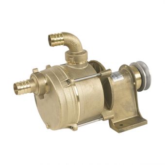
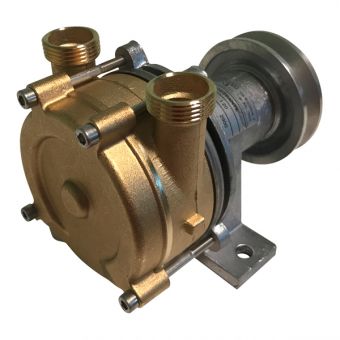
The motorised head pulley shown in FIG. 1 comprises a hydraulic motor 1a, which works on the radial piston principle in the example shown. Further, the motorised head pulley 1 comprises a permanently mounted, stationary shaft 5b, and a pulley 4 rotating around this shaft, which pulley is driven via a reduction gear 2 by the hydraulic motor 1a. In the embodiment shown, the shaft is divided into two sections 5a and 5b, and the radial piston motor 1a is inserted between them and rigidly connected with the shaft sections 5a, 5b. In the example shown, the reduction gear 2 is designed as a planet gear, which like the hydraulic motor 1a is centrally mounted in a cavity 11 in the pulley 4. The planet gear 2 comprises three gear wheels 3, which constitute the planet wheels of the planet gear, and which are pivotally suspended via the shaft journals 12 on an end flange 13 on the motor 1a. The gear wheels 3 mesh with the toothed drive shaft 14 of the hydraulic motor 1a, which drive shaft is the sun wheel of the planet gear, and which also meshes with an internally toothed rim 15 in the internal cavity 11 of the pulley 4. In the embodiment shown, the gear wheels 3 are made of the plastic material polyetherether ketone reinforced with carbon fibres. The shaft journals 12, the drive shaft 14, and the toothed rim 15 are made of metal such as rust-inhibited steel.
The moving parts of the hydraulic motor comprise pairs of sliding surfaces turned towards each other, one of which sliding surfaces is of metal, and the other sliding surface of a plastic material; the pistons may be made of metal, such as steel, and the cylinder walls may be of plastics, such as carbon fibre reinforced polyetherether ketone. The sliding surfaces of the motor, especially the radial sliding surfaces, may comprise sliding surfaces on a steel shaft and sliding surfaces on a support, such as a bushing of plastic material, especially carbon fibre reinforced polyetherether ketone.
All pairs of opposed sliding surfaces between the two mutually movable parts of the reduction gear and also between the mutually moving parts of the motor, are thus designed to be lubricated and cooled by means of a lubricant-free, water-based pressure fluid, so that the surfaces do not weld as a consequence of direct contact between the surfaces without intermediary pressure fluid. At the same time a leak occurring at the motorised head pulley will not result in pollution of the surroundings with an undesirable, oil-based hydraulic medium, as in the case of known motorised head pulleys, but only with harmless water, which is important especially when the motorised head pulley is used for driving a conveyor 10, which forms part of a food processing production. This applies in operation as well as under installation and dismantling of the motorised head pulley in connection with service.
The internal cylindrical cavity 11 of the pulley extends to immediate proximity with the external perimeter of the pulley, and generally in the whole length of the pulley 4. Hereby the pulley heat is led away in a particularly efficient manner via the passing, water-based pressure fluid.
As shown, the stationary, split shaft 5a,5b can be provided with inlets 6, and outlet 7, which are connected through orifices 8, 8a with the central cavity 11 for admission and emission, respectively, of the water-based pressure fluid in the cavity of the pulley.
Thereby the lubricant-free, water-based pressure fluid, which can preferably be corporation water, can quickly remove particularly intense heat, resulting for example by friction between the conveyor 10 and the pulley 4. Hereby a high degree of operational reliability is achieved. Similarly, the water-based pressure fluid will in a particularly efficient manner remove heat from the hydraulic motor 1a and the reduction gear 2, since both are directly surrounded by the pressure fluid. The hydraulic motor 1a may be provided with a non-return valve 9 in the inlet 6 as well as openings 7a for emitting the pressure fluid into the cavity 11.
Incidentally, the non-return valve 9 in the inlet 6 will ensure that the hydraulic motor cannot counter-rotate, which makes it redundant to provide it with further means of braking, such as a mechanical brake.
It should be mentioned that as it is known, the heat conductivity in the known, oil-based pressure liquids is much lower than in water. According to the present invention a particularly reliable and stable service of the motorised head pulley is ensured under service conditions where much heat must be removed. The heat is removed chiefly via the water-based pressure fluid, which is quite impossible in the case of the known motorised head pulleys, which are driven by means of an oil-based pressure fluid.
In conclusion it should be mentioned that many changes may be made without deviating from the principle of the invention itself. For example, the motorised head pulley can be used for driving many different transport devices under circumstances where pollution with oil of the surroundings is unwanted. At the same time, many different combinations of materials can be used for the moving parts of the transmission, including cheaper plastics such as polyamide.
Hydraulic motors are rotary or mechanical actuators that operate by converting hydraulic pressure or fluid energy into torque and angular displacement.
Starting torque is the ability of a hydraulic motor to make a load start moving. The starting torque indicates the amount of torque that a hydraulic motor can develop to make a load start turning. It can be expressed as a fraction or percentage of the theoretical torque. The starting torque for piston, vane, and common gear motors is usually between 70% to 80% of the theoretical value.
Mechanical efficiency measures the effectiveness found in a machine or a mechanical system. This can be obtained from different variables and in hydraulic motors, torque usually is used. In hydraulic motors, mechanical efficiency refers to the ratio of the actual torque to be delivered to the theoretical torque.
Hydraulic motors work by converting hydraulic pressure or fluid energy into torque and angular displacement. Some components operate inside these motors to develop the required. Below is a list of the key components that are used in most hydraulic motors and their corresponding functions
In hydraulic motors, the rotor is the part that rotates after being triggered by a mechanism inside the motor. These mechanisms differ depending on the type of motor, for example in a gear-type hydraulic motor, the rotor starts rotating after meshing of the gears and fluid flow. In a vane type hydraulic motor, the rotor is triggered by the pressing of the vanes.
A driveshaft (also known as a propeller) is part of a hydraulic motor that is responsible for delivering or transferring the torque created inside the motor to the outside environment where it can be used for lifting loads and other applications. Most driveshafts are made of metals and have gear teeth on their ends.
Hydraulic motors operate by manipulation of the flow of fluid inside the motor. Directional control valves are designed to control fluid flow inside the motor. In most hydraulic and pneumatic systems these valves allow the fluids such as oil, water, air to flow from into different parts according to the control patterns and mechanisms of the system.
Hydraulic motors have a casing that protects and contains the components. They are made of different materials such as stainless steel, titanium, cast iron, low carbon steel, nickel, etc. Cases come in various shapes according to the arrangements of the components inside the motor.
A piston rod is a bar that is machined precisely and used to transmit a force created in a hydraulic or pneumatic system to a machine’s component performing the work. In hydraulic motors, piston rods are mainly used in piston-type motors to produce a turning movement.
Hydraulic motors use fluids to transmit energy from one point to another. Most hydraulic motors use water-based, petroleum-based, and synthetic fluids. The widely used is petroleum-based which is also known as mineral-based. This mineral-based product comes in many forms depending on the additives used and the quality of the crude oil used. Common fluid additives include anti-corrosion agents, demulsifiers, extreme pressure agents, rust, oxidation inhibitors, and defoamants.
Bearings are mechanical components that enable the rotation of parts by reducing friction and holding the load. In hydraulic motors the bearing is mainly used on the driveshaft to enable smooth and efficient rotation of the shaft. Many types of bearings are used on rotating shafts and the choice of one depends on many factors such as shaft speed, amount of load, the direction of the load, type of fluid used, etc.
It is important to know and understand how hydraulic pumps and motors differ from each other. Hydraulic pumps and motors operate similarly to each other to such an extent that some people do not know the differences. Some use the word pump when in effect they are talking about a motor and vice versa.
Hydraulic motors can operate in either direction. Hydraulic motors have mechanisms that allow them to rotate in either direction (negative or positive rotation) are required to have positive and negative rotation, which is why their internal structure is symmetrical, and hydraulic pumps generally rotate in a single direction, so that requirement is not necessary.
For example, in a vane motor, the blades can only be arranged in a radial manner. It can not be inclined like a vane pump, because this will cause the blades to be broken when reversing. The distribution plate in the axial plunger motor is supposed to have a symmetrical design, in that case, the axial plunger of the pump is not; the gear motor should have a separate leakage tube.
Hydraulic pumps are mainly used when they are connected with a prime mover and motors are connected with loads. The pump in essence has no radial loads such as pulleys, sprockets, belts which can be found in hydraulic motors.
High-speed low torque (HSLT) hydraulic motors are sometimes referred to as high revs per minute (RPM) motors are designed to operate at high speeds ranging from 1 000 rpm to 14 000 rpm. They are used when the load is light because they have a low torque range. They can be used for applications in the utility, earthmoving, forestry, material handling etc.
In this gear type, the hydraulic motor is made of two gears which are called the driven gear and the idle gear. The driven gear is connected to the output shaft usually by means of a key. Inside the motor is high pressure oil which flows into the sides around the gear tips and flows into the motor housing exiting through the outlet port. In the process, the gears mesh, and this will not allow oil coming from the outlet to flow back into the inlet side.
A small amount of this oil is used for lubrication of the gears. This oil is bled through the bearings (hydrodynamic), and the oil enters through the pressure side of the gears. The spur gears are popularly used in these types of hydraulic motors. If the gears are not manufactured to standards, they may become subject to vibration and may be noisy during the operation of the motor.
Internal gear motors have similar features and characteristics to external gear motors. The smooth operation of the gears characterizes the motors as compared to external gears where they are subjected to vibration causing noisy situations. They have one external gear that is used to mesh with the circumference of a larger gear. Internal gears are found in two versions namely the gerotor motor (mainly used in mobile systems and hydraulic technologies) and the gerotor motor.
In these gear motors a crescent vane is used to separate the discharge volume from the inlet volume between the two gears. When the hydraulic fluid enters through the inlet volume it causes the pressure to increase causing the volume to expand and this results in the gears rotating. The fluid will be forced out as the gears continue to rotate.
Hydraulic motors operate by creating an imbalance due to pressure which results in the rotation of the shaft. In vane motors, this imbalance is a result of the difference when the vane area is exposed to hydraulic pressure. Vane motors have a hydraulic balance which prevents the rotor from sideloading the shaft. The pressure difference develops the torque as the oil from the pump is forced to go through the motor.
Vane motors are usually made of a cartridge configuration of a motor housing. Their design is like that of a vane pump. They are characterized by two-port plates that separate the outlet and inlet ports as they put in between them the cam and rotor ring. Inside the cylindrical case of a vane motor is a ring mounted. This ring is made up of radial slots where there are sliding vanes. The vanes operate by pressing inside, against the wall of the cylindrical case. The ring rotates when the vanes are spring forced against the wall due to centrifugal force.
The radial-piston type hydraulic motor operates by transforming the energy created by the fluid pressure into mechanical energy (rotation). There is a directional valve, which is a fixed and central part of the configuration, it has two lines for fluid flow where one is for draining and another for fluid intake. The rotor is for turning in the directional valve which is fitted with radial bores. This will cause the free-floating pistons to operate.
When the hydraulic fluid, that is pressurized by the pump, gets into the bores it presses the pistons against the stator usually for half a revolution. In the following half revolution, the fluid is delivered into the draining line connected to the directional valve. If the motor is operating under pressure loading on the motor piston, the stator will exert stress on the piston, and this will make the pistons and the rotor rotate. When this happens the output shaft of the motor is driven. Most of these systems are fitted with rollers which reduce the losses caused by piston friction on the track.
Axial piston-type hydraulic motors are also known as barrel motors. In these motors the plate of the drive shaft is positioned at an angle with respect to the barrel of the motor, the intake of fluid in the cylinders results in the movement of the pistons, causing the drive to rotate. In each cylinder, there is 1 phase of output and of intake per rotation. The piston operates when it is applied to the inclined plate with a force proportional to the pressure. This force reduces the angle and creates a force that makes the plate rotate.
When choosing a hydraulic motor to use there are factors that one needs to consider when designing an efficient system. The motor used should match the system requirement and if it does not this might affect the whole system. Below is a list of some of the factors and questions to consider.
There are many applications that hydraulic motors can be used for. These motors are made of different materials meaning they respond differently to operating conditions. Some are strong enough to withstand vibrations and harsh conditions and these are mainly used for industrial applications.
Before one can choose a type of motor to use, they need to gather installation information as well. This is because other motor types require a lot of expertise and are complicated to install. It is essential to talk with professionals about the other costs that are involved before purchasing a hydraulic motor.
A closed-loop in a hydraulic system is also known as a hydrostatic drive and is commonly found in mobile systems and industrial machines such as conveyors. In a closed-loop, the fluid flows directly from the pump to the motor and then returns to the pump without entering a reservoir. The fluid flow determined the speed of the motor. In an open loop, the fluid flows from the motor to the pump through a reservoir. Before choosing the right motor for the system it is essential to understand the loop that will operate in the specific hydraulic system.
Hydraulic motors play a vital role in the engineering and automation of many systems in our everyday lives. Although some of them are complex, most of these motors use simple operating principles which are easy to understand and are user-friendly.

Check that the pump shaft is rotating. Even though coupling guards and C-face mounts can make this difficult to confirm, it is important to establish if your pump shaft is rotating. If it isn’t, this could be an indication of a more severe issue, and this should be investigated immediately.
Check the oil level. This one tends to be the more obvious check, as it is often one of the only factors inspected before the pump is changed. The oil level should be three inches above the pump suction. Otherwise, a vortex can form in the reservoir, allowing air into the pump.
What does the pump sound like when it is operating normally? Vane pumps generally are quieter than piston and gear pumps. If the pump has a high-pitched whining sound, it most likely is cavitating. If it has a knocking sound, like marbles rattling around, then aeration is the likely cause.
Cavitation is the formation and collapse of air cavities in the liquid. When the pump cannot get the total volume of oil it needs, cavitation occurs. Hydraulic oil contains approximately nine percent dissolved air. When the pump does not receive adequate oil volume at its suction port, high vacuum pressure occurs.
This dissolved air is pulled out of the oil on the suction side and then collapses or implodes on the pressure side. The implosions produce a very steady, high-pitched sound. As the air bubbles collapse, the inside of the pump is damaged.
While cavitation is a devastating development, with proper preventative maintenance practices and a quality monitoring system, early detection and deterrence remain attainable goals. UE System’s UltraTrak 850S CD pump cavitation sensor is a Smart Analog Sensor designed and optimized to detect cavitation on pumps earlier by measuring the ultrasound produced as cavitation starts to develop early-onset bubbles in the pump. By continuously monitoring the impact caused by cavitation, the system provides a simple, single value to trend and alert when cavitation is occurring.
The oil viscosity is too high. Low oil temperature increases the oil viscosity, making it harder for the oil to reach the pump. Most hydraulic systems should not be started with the oil any colder than 40°F and should not be put under load until the oil is at least 70°F.
Many reservoirs do not have heaters, particularly in the South. Even when heaters are available, they are often disconnected. While the damage may not be immediate, if a pump is continually started up when the oil is too cold, the pump will fail prematurely.
The suction filter or strainer is contaminated. A strainer is typically 74 or 149 microns in size and is used to keep “large” particles out of the pump. The strainer may be located inside or outside the reservoir. Strainers located inside the reservoir are out of sight and out of mind. Many times, maintenance personnel are not even aware that there is a strainer in the reservoir.
The suction strainer should be removed from the line or reservoir and cleaned a minimum of once a year. Years ago, a plant sought out help to troubleshoot a system that had already had five pumps changed within a single week. Upon closer inspection, it was discovered that the breather cap was missing, allowing dirty air to flow directly into the reservoir.
A check of the hydraulic schematic showed a strainer in the suction line inside the tank. When the strainer was removed, a shop rag was found wrapped around the screen mesh. Apparently, someone had used the rag to plug the breather cap opening, and it had then fallen into the tank. Contamination can come from a variety of different sources, so it pays to be vigilant and responsible with our practices and reliability measures.
The electric motor is driving the hydraulic pump at a speed that is higher than the pump’s rating. All pumps have a recommended maximum drive speed. If the speed is too high, a higher volume of oil will be needed at the suction port.
Due to the size of the suction port, adequate oil cannot fill the suction cavity in the pump, resulting in cavitation. Although this rarely happens, some pumps are rated at a maximum drive speed of 1,200 revolutions per minute (RPM), while others have a maximum speed of 3,600 RPM. The drive speed should be checked any time a pump is replaced with a different brand or model.
Every one of these devastating causes of cavitation threatens to cause major, irreversible damage to your equipment. Therefore, it’s not only critical to have proper, proactive practices in place, but also a monitoring system that can continuously protect your valuable assets, such as UE System’s UltraTrak 850S CD pump cavitation senor. These sensors regularly monitor the health of your pumps and alert you immediately if cavitation symptoms are present, allowing you to take corrective action before it’s too late.
Aeration is sometimes known as pseudo cavitation because air is entering the pump suction cavity. However, the causes of aeration are entirely different than that of cavitation. While cavitation pulls air out of the oil, aeration is the result of outside air entering the pump’s suction line.
Several factors can cause aeration, including an air leak in the suction line. This could be in the form of a loose connection, a cracked line, or an improper fitting seal. One method of finding the leak is to squirt oil around the suction line fittings. The fluid will be momentarily drawn into the suction line, and the knocking sound inside the pump will stop for a short period of time once the airflow path is found.
A bad shaft seal can also cause aeration if the system is supplied by one or more fixed displacement pumps. Oil that bypasses inside a fixed displacement pump is ported back to the suction port. If the shaft seal is worn or damaged, air can flow through the seal and into the pump’s suction cavity.
As mentioned previously, if the oil level is too low, oil can enter the suction line and flow into the pump. Therefore, always check the oil level with all cylinders in the retracted position.
If a new pump is installed and pressure will not build, the shaft may be rotating in the wrong direction. Some gear pumps can be rotated in either direction, but most have an arrow on the housing indicating the direction of rotation, as depicted in Figure 2.
Pump rotation should always be viewed from the shaft end. If the pump is rotated in the wrong direction, adequate fluid will not fill the suction port due to the pump’s internal design.
A fixed displacement pump delivers a constant volume of oil for a given shaft speed. A relief valve must be included downstream of the pump to limit the maximum pressure in the system.
After the visual and sound checks are made, the next step is to determine whether you have a volume or pressure problem. If the pressure will not build to the desired level, isolate the pump and relief valve from the system. This can be done by closing a valve, plugging the line downstream, or blocking the relief valve. If the pressure builds when this is done, there is a component downstream of the isolation point that is bypassing. If the pressure does not build up, the pump or relief valve is bad.
If the system is operating at a slower speed, a volume problem exists. Pumps wear over time, which results in less oil being delivered. While a flow meter can be installed in the pump’s outlet line, this is not always practical, as the proper fittings and adapters may not be available. To determine if the pump is badly worn and bypassing, first check the current to the electric motor. If possible, this test should be made when the pump is new to establish a reference. Electric motor horsepower is relative to the hydraulic horsepower required by the system.
For example, if a 50-GPM pump is used and the maximum pressure is 1,500 psi, a 50-hp motor will be required. If the pump is delivering less oil than when it was new, the current to drive the pump will drop. A 230-volt, 50-hp motor has an average full load rating of 130 amps. If the amperage is considerably lower, the pump is most likely bypassing and should be changed.
Figure 4.To isolate a fixed displacement pump and relief valve from the system, close a valve or plug the line downstream (left). If pressure builds, a component downstream of the isolation point is bypassing (right).
The most common type of variable displacement pump is the pressure-compensating design. The compensator setting limits the maximum pressure at the pump’s outlet port. The pump should be isolated as described for the fixed displacement pump.
If pressure does not build up, the relief valve or pump compensator may be bad. Prior to checking either component, perform the necessary lockout procedures and verify that the pressure at the outlet port is zero psi. The relief valve and compensator can then be taken apart and checked for contamination, wear, and broken springs.
Install a flow meter in the case drain line and check the flow rate. Most variable displacement pumps bypass one to three percent of the maximum pump volume through the case drain line. If the flow rate reaches 10 percent, the pump should be changed. Permanently installing a flow meter in the case drain line is an excellent reliability and troubleshooting tool.
Ensure the compensator is 200 psi above the maximum load pressure. If set too low, the compensator spool will shift and start reducing the pump volume when the system is calling for maximum volume.
Performing these recommended tests should help you make good decisions about the condition of your pumps or the cause of pump failures. If you change a pump, have a reason for changing it. Don’t just do it because you have a spare one in stock.
Conduct a reliability assessment on each of your hydraulic systems so when an issue occurs, you will have current pressure and temperature readings to consult.
Al Smiley is the president of GPM Hydraulic Consulting Inc., located in Monroe, Georgia. Since 1994, GPM has provided hydraulic training, consulting and reliability assessments to companies in t...


 8613371530291