
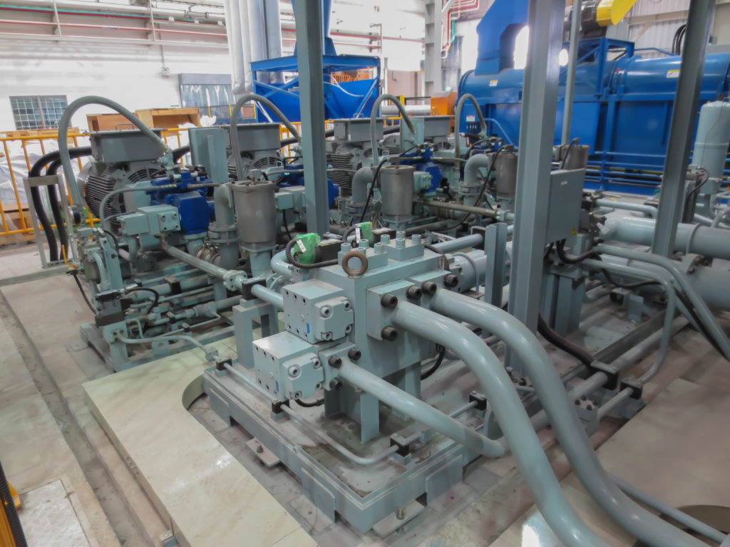
reversing hydraulic pump factory

Gear pumps leak oil between the gears, while a piston (such as used in car engines) does not. This means the piston pump will place the cylinder ram exactly where it is required, positioning the rudder accurately. This gives far sharper steering, reducingunnecessary course corrections meaning battery consumption on Octopus pumps is up to half that of other pumps.
Leading autopilot manufacturers choose Octopus pumps for their non RFB pilot systems which do not have a Rudder Feedback unit. Previously, slop in the system caused by gear leakage meant that a Rudder Feedback unit was necessary to tell the pilot the exact rudder position. As Octopus pumps will always bring the ram back to the required position the Rudder Feedback unit is not required, which also greatly simplifies installation.
A professional installation should always have a method of isolating the pump from the steering system – Octopus pumps feature inbuilt shut off valves in the pump manifold.
A pump that does not have variable flow (unless dedicated to a range of cylinders such as our fixed 0.8L pump) will be operating too fast or too slow in 90% of cases. Autopilot manufacturers get around this problem by adjusting the output to the pump to compensate, which either forces the pump to operate for longer periods of time which increases power consumption and wear on the parts, or it will operate at high pressure for short periods of time – also putting unnecessary strain and wear on the system.
Octopus Variable Flow Reversing Pumps precisely control the speed of the ram, reducing unnecessary battery consumption, pressure, strain and wear on the hydraulic system.
The flow rate of the pump can be set to get the best hard over time (cylinder ram speed) for the particular boat. There is a simple equation to calculate the hard over time:
The flow rate on the pump can be adjusted so that the hard over time is between 10 & 20 seconds – select which is most suitable for the particular boat.

Our New Gear Pump Offers Industry-Leading Reliability and Performance in a Smaller, Lighter, Quieter Package.We are excited to introduce our new 2 and 3L configurations suitable for cylinders all the way to 40Ci.
Cost Savings – the increased efficiency and performance means the pumps can be used with smaller autopilot course computers than equivalent drive units.

Accu-Steer hydraulic reversing pump units are designed to interface hydraulic steering systems with autopilot or electric steering control systems. Please click on the images below for details about our various models of Hydraulic Reversing Pump-Sets for Autopilots.

Manufactured in our factory in the UK and designed for the marine autopilot market, these quiet gear pumps are the drives of choice for major autopilot manufacturers around the world. The range from 0.6 to 2.5 litres per minute, is water resistant to IP67 and fully certified to the Recreational Craft Directive (including ignition protection) and the navigational EMC standard. With low power consumption and high performance, these pumps are ideal for all types of marine craft and other applications from snow-blowers to dentists chairs.

Motor-Reversing System. The illustration below, shows a power-driven pump operating a reversible rotary motor. A reversing valve directs fluid to either side of the motor and back to the reservoir. A relief valve protects the system against excess pressure and can bypass pump output to the reservoir, if pressure rises too high.
One of the biggest limitations of a traditional centrifugal pump is its inability to reverse the direction of flow. By design it can only be run in one rotation and one direction of flow. Liquid enters the eye of the impeller at the suction port (typically on the front of the pump), is pushed out radially, and exits the pump at the discharge port (typically on top of the pump). For most centrifugal pumps the suction port is larger than the discharge port to better feed liquid into the pump, and to remove any confusion as to which port is “in” and which port is “out.” Rotation arrows can be found cast onto the pump or printed on the nameplate to make it perfectly clear that these pumps run in one direction of rotation and one direction of flow.
Which brings us to the subject at hand: running internal gear pumps in reverse. They can be easily converted from one direction of rotation and flow to the other; or even be made to run in two directions of rotation and in two directions of flow. The capacity of the pump remains constant in either direction, making this a beneficial and unique feature of the Internal Gear pumping principle.
The most common reason for changing a pump’s rotation is to accommodate the system. If the supply tank is on the right, then it’s not ideal to have the inlet port on the left. “Creative” piping can be used to accommodate the pump, but changing the pump’s rotation to swap the inlet and outlet ports makes for a cleaner system design, and avoids adding extra length and restrictions to the inlet piping. The pump can be ordered and built in either rotation, but sometimes the pump comes from your inventory or from another part of your facility. Rotation changes can happen for a variety of reasons.
Another common example is a pump which is going to be run in both rotations and both directions of flow. This is common for customers loading or unloading liquids through hoses or manifolds. Once the load is complete, they briefly run the pump in reverse to strip-clean the pipes. In these cases, there’s a primary direction of rotation and flow in which the pump runs most often, and a secondary direction of rotation and flow which is less frequent and usually shorter duration.
There are some outliers…designs of internal gear pumps that cannot be reversed. Before we get too far down this path it’s best to check first to make sure your pump does not show any “red flags” that would indicate that they fall into this group of “directional” pumps.
The first “red flag” would be a rotation arrow on the casting or nameplate of the pump. Common examples for Viking Pump include Mag Drive pumps from the 895 Series™ (rotation arrow on the nameplate), or the 4 inch and larger Motor Speed pumps from the 4195 Series™ (rotation arrow cast into the head). In either case, these pumps have design features that make them rotational, so running them in reverse rotation is not advised.
The second “red flag” would be differences in port sizes. Internal Gear pumps typically feature identical port sizes so that the inlet and outlet can be swapped. However, some pumps are designed to have a designated inlet and outlet port. In these cases, the inlet is always larger than the outlet for the same reason that this is done in centrifugal pumps (to better feed liquid into the pump and to remove any confusion as to which port is “in” and which port is “out”.)
Viking pump-mounted relief valves, whether internal or return-to-tank, are directional. They only provide over-pressure protection in one direction of rotation and flow. Most are reversible though. By removing the valve from the pump, swapping the orientation by 180°, and reinstalling it, the direction of overpressure protection for the pump reversed. Modifying the valve orientation is the most common required modification for changing the direction of flow of an Internal Gear pump.
First, there are a few Viking models where the relief valve is not a separate component, but rather built into the body of the pump itself. One common example of this is the smallest 432 Series™ sizes where the valve is built into the casing. For these models the direction of overpressure protection cannot be reversed.
Second, if a pump is to be run in both directions this could mean that an overpressure, upset condition could occur on either side of the pump. If running the pump in both directions, both sides of the pump need over-pressure protection. A Viking internal relief valve, which only functions in one direction of flow, could not be used as the only means of over-pressure protection.
Many pumps feature either an internal or external seal circulation plan. These include internal holes or external tubing which route pumped fluid through the seal chamber to help lubricate, and ultimately extend the life of, the seal and pump parts. Common examples include an API Plan 11 (or flush line), or an API Plan 13 (or suckback line). For these seal circulation plans a line is connected between the seal (or stuffing box) to the discharge port or suction port, respectively.
Reversing the rotation of the pump and direction of flow will reverse the flow through the seal plan, turning a Plan 11 into a Plan 13 (or vice versa). For some applications either API plan may be acceptable and no modifications would be needed. For others the appropriate seal circulation plan should be used; the line would need to be removed and replaced accordingly.
In a few models, the seal circulation plan is internal to the pump, and may or may not be easily changed. A common example of this is the 75 Series™, where a hole in the suction port ensures fresh liquid and low pressure at the seal. For these pumps the discharge side hole is plugged. When changing the direction of rotation, it would be necessary to move this plug to the other side of the casing.
Some Internal Gear Pump models and sizes feature additional paths for internal lubrication of bushings, or to improve flow behind the rotor. A common feature is the pressure lubricated idler pin, which has a hole that allows liquid to be fed in from the discharge side of the pump and exit underneath the bushing. This helps to ensure the bushing and pin always have plenty of lubrication, and the life of these parts is extended. When reversing the rotation of the pump, this internal lubrication path reverses. While still providing lubrication, its effectiveness is somewhat diminished. It’s preferable to have the discharge side hole open to pressure-feed the idler pin. Often this can be done by sampling changing the location of a pipe plug (though some models and sizes feature check valves which require no modification to change direction).
Another, though somewhat less common, internal lubrication option is a casing groove. These are used to promote flow behind the rotor for liquids that may set up or settle out in the back of the casing. Casings with two grooves can be run in either direction. Casings with one groove are directional, and should be replaced before changing the primary pump rotation. In some cases a pump may be suitable running with either a flush groove (discharge side) or suckback groove (inlet side), but this should always be checked with your authorized Viking Pump distributor before making this change.
Fitted properly, most Viking Internal Gear Pumps can be run in either direction or both! After checking the list from above and making the proposed changes you will be ready to roll in a new direction.

This item is brand-new, factory sealed.Use For Most Hydraulically Steered Boats And Applications; 1000 PSI; 16 Cubic Inch To 30 Cubic Inch Capacity; 12 Volt DC; 6 Amp To 40 Amp; Floor Mount; 14 Degree Fahrenheit To 122 Degree Fahrenheit Operating Temperature

Manufactured in our factory in the UK and designed for the marine autopilot market, these quiet gear pumps are the drives of choice for major autopilot manufacturers around the world. The range from 0.6 to 2.5 litres per minute is water resistant to IP67 and fully certified to the Recreational Craft Directive (including ignition protection) and the navigational EMC standard. With low power consumption and high performance these pumps are ideal for all types of marine craft and other applications from snow-blowers to dentists chairs.
Backed with over 30 years of continuous development the PR+ range of reversing pumps presents the ultimate in quiet and smooth operation. Unlike noisy piston pump designs the precision gear form delivers smooth flow in all conditions and with minimal noise. Now with IP67 motors that have a 4000 hour brush life these latest generation of Hydraulic Projects power units are the best available. With low power consumption and high performance these pumps are ideal for all types of marine craft and other applications from snow-blowers to dentists chairs.
The PR+ pumps are available in 0.6, 0.8, 1.0, 1.5, 2.0 and 2.5 litre per minute flows. Pilot check valves are fitted as standard, they can be used with both balanced and unbalanced cylinders. PR+ pumps have an advanced protective coating designed especially for the salt laden atmosphere of the marine environment.
It is important to select the correct size of pump as it directly influences the ability of the Autopilot to steer the vessel. If the pump is too large, the vessel may over steer and will use more power; if it is is too small then the Autopilot may struggle to maintain a course.
“Hard Over Time” is the time that the pump takes to drive the rudder from port to starboard. An Autopilot Drive will need to give a nominal “Hard over time” of 10 to 12 seconds unless otherwise specified by the Autopilot manufacturer. The type of vessel to be steered must be considered as the “Hard over time” may be faster on lightweight planing craft / modern yachts and slower on displacement power boats/ long keel yachts.
To use the table in our product pictures, you will need to know the volume of your steering cylinder, then simply select the "Hard over time" that you require. Follow the column down until you approximately match your cylinder volume and then select the pump on that row. If your cylinder has a smaller volume then it will have a faster “Hard Over Time”, but if it is larger, it will have a slower “ Hard Over Time”.


 8613371530291