
rexroth hydraulic pump adjustment factory
Variable-displacement pumps are used in hydraulic systems where the flow requirements vary. This usually means the system has several actuators and, depending on the current cycle of the machine, the number of actuators moving at a given time will fluctuate. The most common type of variable-displacement pump is the pressure-compensating pump.
Pressure-compensating pumps are designed to deliver only the amount of flow required by the system to maximize efficiency and avoid heat generation. The compensator is adjusted to a pressure somewhat higher than that required to move the system’s heaviest load.
A pressure-compensating pump will deliver its maximum flow until the system pressure reaches the compensator setting. Once the compensator setting is reached, the pump will be de-stroked to deliver only the amount of flow that will maintain the compensator setting in the line.
Whenever more flow is demanded by the system (such as would occur when an additional actuator begins to move), the pump will increase its stroke to meet the new flow demand. Whenever the system flow needs to decrease (such as when one or more actuators are stopped), the pump stroke is reduced.
When the system is stopped completely, the pump stroke is reduced almost to zero. It will stroke only a very small amount or whatever is required to maintain the compensator setting in the line, overcoming any system bypassing or leaks. While a pressure-compensating pump is efficient, the standby pressure remains high.
Adjusting a pressure-compensating pump is quite simple. With all flow blocked and the system idle, the compensator valve is adjusted to the desired pressure. However, some pressure-compensating pumps have two valves mounted on the pump body.
The two adjustments can look nearly identical. This type of pressure-compensating pump is called a load-sensing pump. The second adjustment is called either a “load-sensing” valve or “flow-compensator” valve.
A load-sensing pump is designed to reduce its pressure to a much lower standby level whenever the system is idle. This can conserve energy and reduce heat and wear in systems that spend a significant amount of time in an idle condition.
The two separate pressure adjustments allow setting the compensator valve to the required maximum system pressure and the load-sensing adjustment to a much lower standby pressure.
Whenever the system is moving a load, the high-pressure adjustment limits the system pressure. For instance, as a cylinder is extended, pressure in the system will build as necessary to move the load. Eventually, the cylinder reaches the end of its stroke, and flow is blocked.
Most load-sensing systems have a pump-loading directional-control valve of some sort that can place the system in an idle condition until it is necessary to move another load. When the pump-loading valve is shifted, the system pressure drops to the much lower load-sensing valve setting.
A load-sensing valve usually is smaller than the compensator valve and typically mounted directly on top of the compensator. The compensator valve is closer to the pump. The load-sensing valve is factory preset and normally does not need to be adjusted during the initial pump setup. In most pumps, the factory preset is approximately 200-300 pounds per square inch (psi).
The most common reason to adjust a load-sensing valve is because someone unfamiliar with the pump has mistakenly attempted to set the maximum system pressure by adjusting the load-sensing valve instead of the compensator. This not only can result in unstable system pressure but in some cases can also void any warranty on the pump.
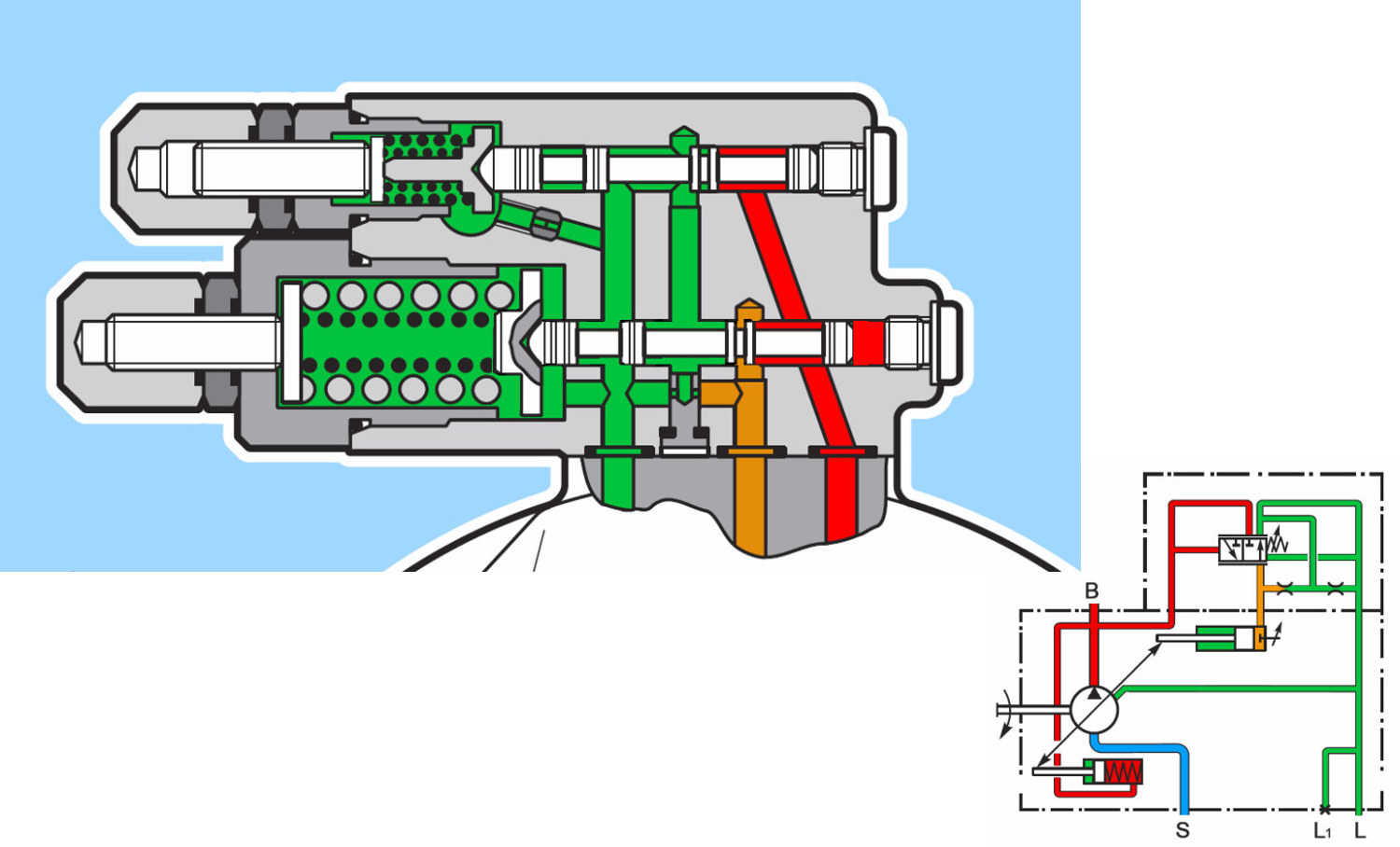
A typical configuration of a pressure-compensating pump is shown in Figure 1. A pump-loading valve is used to determine whether the system is idle or prepared to move a load. The pump-loading valve is de-energized whenever the system is idle.
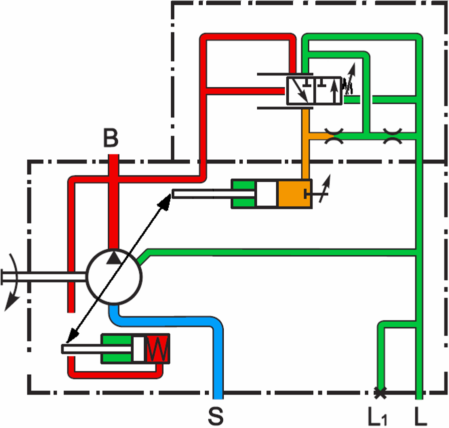
Pilot pressure on the left-hand side of the load-sensing valve is then released to the tank. The pilot line on the right-hand side of the load-sensing valve is connected to the pressure line at the pump outlet. System pressure shifts the load-sensing valve and directs pressure to reduce the pump stroke so that system pressure drops to the load-sensing setting of 300 psi, as illustrated in Figure 2.
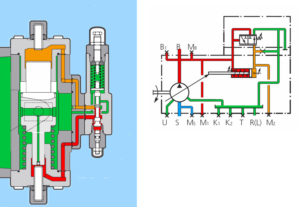
When a load is to be moved, the pump-loading valve is energized. This directs pilot pressure to the left side of the load-sensing valve, keeping it from shifting. System pressure shifts the compensator valve to de-stroke the pump exactly the amount necessary to limit system pressure to the compensator setting, 3,000 psi as shown in Figure 3.
To make the pressure settings, always adjust the load-sensing valve first. The pump should be deadheaded by closing the manual hand valve. With the pump-loading valve de-energized, pressure will build only to the current setting of the load-sensing valve. Adjust the load-sensing valve to the desired pressure.
Once the load-sensing valve is set, energize the pump-loading valve. System pressure will then build to the current compensator setting. Adjust the compensator to the desired setting. Open the manual valve, and the system can be placed back into service.
Jack Weeks is a hydraulic instructor and consultant for GPM Hydraulic Consulting. Since 1997 he has trained thousands of electricians and mechanics in hydraulic troubleshooting methods. Jack has...
Rexroth’s complete line of hydraulic pumps serve virtually every industry in manufacturing and technology applications such as railway engineering, chemical process plants, power and environmental engineering, automotive engineering, plastics processing machinery, paper industry, presses, test rigs and simulation systems, marine/offshore engineering, special projects, and civil/water engineering, transportation technology, and machine tools.
Pursuing a comprehensive understanding of these application areas and working closely with customers, our engineers have developed unique electrohydraulic innovations in control technology. The result is hydraulic pumps with greater precision, dependability, and reliability.
Keeping a market expectations mindset, Bosch Rexroth is setting a new standard for hydraulic pumps with continuous development at the highest standards and quality. Rexroth pumps are designed for high reliability and efficiency.
The lineup of pumps includes: Axial Piston Pumps, External Gear Pumps, Internal Gear Pumps, Gerotor Pumps, Vane Pumps, Radial Piston Pumps and Electro-hydraulic Pumps.
Rexroth pumps are designed as a solution point of view where the products are compatible with each other in order to provide a whole portfolio for our customers.
To help keep your systems operating safely and at maximum efficiency, Rexroth offers a wide range of pump accessories. Replacement seals, safety valve, mounting flanges, brackets, and adapters make installation easier and faster.
Continuous development within hydraulic pumps industry and latest technologies at the highest level of development Bosch Rexroth will always provide the best matched reliable products for your business.

Electrical Motors & Wiring • Rexroth Hydraulic Pumps • Adjusting the Pump • Adjusting Flow & Pressure • Adjusting the Control Valve • Troubleshooting Guide • Formulas & Data • Pump Specifications •
This section of the installation manual deals with the set up and adjustment proce-dure for both the Rexroth A11 pump and Danfoss valve, and it gives a generaldescription on the principle of operation of the pump and control valves and isintended to give the Mechanic a better understanding of the importance of the vari-ous adjustments and their effect on the system. A trouble shooting guide is alsoincluded at the end of this manual.
The model of pump, control valve and electric motors may vary depending on theboom system, however, their installation and adjustment procedures remain muchthe same. Following the steps in the order as listed in the manual will save youtime and possible rework.
1) Install the power pack so that the warm air blown out by the motors will not enter the motors again. Theminimum distance between the wall and the inlet should be approximately a quarter of the inlet openingdiameter.2) The electrical wiring of the power pack must be undertaken only by a qualified electrician. Both electricmotors used on the hydraulic pump and cooling fan should be wired in a three phase delta configuration toprovide optimum power unless stated otherwise.3) Make sure to use the correct cable specifications, based on the rated current stamped on the name plate.In high altitude applications the motor may be derated.4) Before energizing the motors make certain the grounding complies with the recommended standards.Also ensure the hydraulic tank is full and the pump has been cleared of all air locks.5) The electrician must ensure the direction of rotation of the motors are correct. If the direction of rotationis reversed the hydraulic pump will be seriously damaged in a very short period of time. Jog the motor toverify the direction of rotation.6) The motors must start up and run smoothly in the correct direction. In case this does not occur, turn itoff immediately and check the connections before re-starting.7) Run the motor and check the current at the rated full load*. Compare the power generated hydraulicallyto that dissipated in the electric motor and then check it against the maximum current rating stamped onthe name plate of the electric motor. The equation to determine the power available in the hydraulic systemis as follows: HORSE POWER = [FLOW (GPM) x PRESSURE (PSI)] / [1714 x efficiency]And the power consumed by the electric motor is: HORSE POWER = 1.73 x LINE VOLTAGE x LINE CURRENT x COS Ø ÷ 746Take cos Ø to be 0.8 and pump efficiency at 93%
* Rated full load : This condition is achieved when the hydraulic pump is delivering the full flow at themaximum system pressure. Use a flow meter on the breaker circuit to perform this test.
This type of pump is capable of delivering both the required oil flow and pressure depending on the sys-tems demand. The pump will de-stroke and draw very little power from the electric motor when none ofthe hydraulic actuators are in use; this type of pump is commonly referred to as a variable displacementhydraulic pump. Used with a control valve having load sensing features utilizes the load sensing capabili-ties of this pump.
Load SensingThe load sensing pump is commonly used in the implement and steering systems of mobile equipment. Itis also exclusively used in all stationary boom systems. The pump can be set to run at a pre-set standbypressure. The pump will, on demand, supply the required pressure.
Testing and Adjusting Procedure.There are four external adjusting screws provided to control the operating flow and pressure of the pump.Maximum Flow - mechanical stop.Minimum Flow - mechanical stop.Maximum Pressure - hydraulic spool.Standby Pressure - hydraulic spool.
Maximum FlowThis controls the maximum flow the pump will deliver. It is a mechanical stop which limits the maximumangle the swash plate is permitted to incline. The screw is used during initial set up of the pump to adjustthe maximum flow at a given pressure.
Minimum Flow (Do Not Adjust)This control the minimum angle the swash plate is permitted to incline. This adjustment is factory set andshould only be readjusted by qualified personnel.
Standby Pressure (Load Sensing) ValveThis adjustment controls the pump standby pressure. A piston and cylinder arrangement within the pumpuses the pressure drop from this valve to de-stroke the swash plate against a spring applied force. A typicalsetting for this would be 450 psi. The pump will then de-stroke and draw very little power from the drivemotor. A load sense signal amplifier may be used on the load sensing line to ensure a strong signal. Thisgreatly reduces the pressure drop in the system when there is a sudden demand for oil flow.
BLEEDING THE HYDRAULIC PUMPFill the hydraulic tank with the recommended oil. Slacken the case drain line at the pump and release anyair that may be trapped. The head of oil in the hydraulic tank will help to push the air through. Once aclean flow of oil passes through the case drain port of the pump, tighten the hose and wipe up any oil thathas spilled.
TOOLS REQUIREDPressure Gauge (1000453) - Supplied in Tool kitHydraulic Flow Meter with Pressure Gauge- Not suppliedHexagon keys (3 - 8 mm)- Not suppliedCombination Wrenches (8 to 28 mm)- Not suppliedMain Relief Adjustment Tool (V9000-10, PVG 120/32 Only)- Not supplied
The hydraulic pump has three adjustments which must be checked and set to the required specification ascalled for in breaker service manual. The system standby pressure must be also set to 450 PSI.At this stage it is assumed that all hydraulic lines have been connected as illustrated in the installationmanual for the boom system, the hydraulic tank has been filled with the recommended oil, the pump bledof all air locks and the wiring to the entire electrical system is completed.
ADJUSTING THE PUMP STANDBY PRESSURE1) Connect the 1000453 pressure gauge to the Danfoss control valve main pressure port; (P) on a PVG 32valve and (MA) on a PVG 120/32 (See Figure 3).2) Start the hydraulic pump and observe the reading on the gauge. The pressure should be adjusted to 450PSI.3) The adjustment for the standby pressure is done through the compensator valve which is mounted on thehydraulic pump. Remove the cap (if fitted), loosen the lock nut and turn the adjustment screw until thestandby pressure is 450 psi at the main pressure port on the Danfoss valve.4) Turning the screw clockwise increases pressure while turning counter-clockwise decreases the pressure.5) Hold the adjustment screw in place and tighten the locknut.6) Check standby pressure gauge again to verify the reading.
Note:The main relief pressure on the Danfoss valve must be set at this point. Refer to page 8. The pump pres-sure adjustment setting determines the maximum pressure the pump can reach. Therefore this setting mustbe higher than 450psi before the standby pressure can be adjusted.
1) Connect the flow meter to the two hydraulic lines of the breaker. Make sure the pressure line is connect-ed to the inlet port and the return to the outlet port of the flow meter. Wrong connections may damage theflow meter!2) With the pump operating activate the breaker fire button.3) Slowly close the restrictor valve on the flow meter. At a certain point the flow rate will drop off veryrapidly. Take the flow and pressure readings just prior to this.4) If the figures for the flow rate and /or pressure are not met as set out in the breaker service manual pro-ceed to adjust as follows:
SYSTEM MAXIMUM PRESSURE ADJUSTMENT (Unloading)The adjustment for this is on the pressure compensator mounted on the hydraulic pump. The pressure willincrease when the screw is turned in and decrease when turned out. Adjust the pressure as set out in theboom or vehicle service manual. On completion, lock the adjusting screw and replace the protective cover.
PUMP FLOW ADJUSTMENTThe rate of discharge from the pump is controlled by the angle the swash plate is permitted to incline. Thismaximum angle is limited by the length of the adjusting screw. Turning the screw out, increases the flowrate. Turning it in, reduces the flow. Due to the opposing spring forces of the rotary group the swash platewill not follow the adjustment screw when the pump is not rotating. Therefore, the adjustment must bedone with the pump delivering close to the maximum flow, in a no load situation. To adjust, remove theprotective cap, loosen the lock nut and turn the hex screw until the pump is delivering the correct flow atthe specified pressure. See page 13 for adjustment per revolution of stroke limiter.
METHOD ‘B’: SETTING THE PUMP UNLOADING WITHOUT A FLOW METERIn the event a flow meter is not available the pump unloading pressure can be set using the 1000453Pressure Gauge. The pump flow set at the factory is approximate and will generally function withinacceptable limits.1) Connect the Pressure Gauge (p/n 1000453) to the pressure port (“P” on PVG32 and “MA” onPVG120/32).2) Pull the breaker fire lever to fully open position.3) Note the pressure reading on the Pressure Gauge.4) Adjust the pump unloading pressure (max press) as specified in the hydraulic schematic.see System Maximum Pressure Adjustment, above.
The Danfoss Control valve is built up of individual sections and each section has four adjustments. Two ofthese control load sensing pressure to their respective ports, while the other two control the flow rate. Theinstallation manual for the boom system sets out the required pressure for each circuit. The flow rate gov-erns the speed at which the various hydraulic cylinders extend and retract and is generally set to suit theoperator and the application for which the boom system is used. Flow & Pressure adjustments are coveredon page 9. All adjustments are done with the hydraulic pump in operation and the respective control leveractuated.
ADJUSTMENT OF THE MAIN RELIEF VALVE (Figure 3 & 4 )The main relief valve is located on the main section of the Danfoss control valve and must be set to 200PSI higher than the pump unloading pressure.
1) Connect the flow meter as described in page 7. Note: If no flow meter is available connect the 1000453pressure gauge to the main pressure port, pull the breaker fire lever back on the control valveand omit step 3.2) Turn in the main relief valve in three full turns.3) Fully close the flow restrictor valve on the flow meter.4) Adjust the maximum pump pressure to 300 PSI greater than specified in the hydraulic schematic. (refer to page 7 for pressure adjustment ).5) With the breaker circuit activated, back off the main relief valve until the circuit pressure drops to200 PSI higher than the specified pump unloading pressure.6) Return to page 7 and adjust hydraulic oil flow and pressure to the breaker circuit.
PORT PRESSURE ADJUSTMENT (Fig. 5).1) Connect the 1000453 pressure gauge to the circuit pressure port (stamped ‘LS’) as shown.2) Pry out the rubber plugs over the adjusting screws.3) Move the hydraulic cylinder in the circuit being adjusted to its full stroke.4) Hold the valve open and make the adjustment to the circuit using a 6 mm Allan wrench (8mm onPVG120/32 Valves). Turning the screw in increases this pressure while turning it out will reduce circuitpressure.5) Replace the rubber plug over the adjusting screw.6) Repeat the above procedure for all of the other hydraulic circuits with the exception of the breaker.
ADJUSTMENT OF THE BOOM DOWN PRESSURE CIRCUIT ON THE TT AND SX SERIES BOOMSThe SX and TT series booms require a special procedure to adjust the down pressure of the boom"s hoistcylinders.Fig (1) shows the pressure reducing valve and Anti blank fire switch. Fig (2) shows the pressure reliefvalve.
ADJUSTMENT PROCEDURE1) Start by loosening the lock nut and fully turning in the adjustment on the pressure Relief valve.2) Loosen the lock nut and fully decrease the pressure setting of the pressure reducing valve to a minimumsetting.3) Install a 1000 psi pressure gauge on the pressure Relief valve as shown in Fig(1)4) Start the pump and lower the boom using the hoist down circuit. Adjust the pressure reducing valve to325 psi with the use of the gauge while the boom down lever on the Danfoss valve is activated.5) Disconnect the Hersman plug. Using an electrical Multi Meter across pin 1 & 3 and adjust the AntiBlank Fire switch to just close at this pressure of 325 PSI. Replace the Hershman plug.6) Increase the setting of the pressure reducing valve to 600psi.7) Adjust the pressure relief valve on the boom down circuit so that the gauge on the pressure reducingvalve reads 475 PSI. Lock the adjustment.8) Re adjust the pressure reducing valve so that the gauge reads 350PSI and lock the adjustment.
SPEED ADJUSTMENT (FLOW) ( Fig 5A )1) Loosen the lock nut on the adjusting screw.2) Move the respective lever to its fully open position and turn the adjusting screw until the desired speedis obtained.3) Hold adjustment screw in place and lock it using the lock nut.4) Repeat the above procedure for all of the other circuits.5) The adjustment for the breaker circuit should be set to the fully open position to permit maximum flowwhen the circuit is activated.
Pump slows down or Motor not wired in a three phase delta con- Re-wire in Delta configuration.stalls on load. figuration. Check power source. Low voltage supply. Adjust unloading pressure. High unloading pressure.
Wrong adjustment on SWASH plate. Adjust pump.Flow rate of pump Wrong grade of oil. Re-fill with recommended oil.below specification. Worn pump. Replace pump. Pump speed too low. Check motor and wiring. Sticky spools on Compensator valve. Remove and clean spools.
Slow hammer fire. Low flow rate on hammer circuit. Adjust flow on pump. Contaminated hydraulic system. Clean affected components.
Pump Seal Kits: 71cc - 1004192, 100cc - 1005010, 140cc - 1005342Adjustment /1 Rev of Stroke Limiter: 71cc = .287ci , 100cc = .375ci , 140cc = .43ci
Hydraulic pumps are used in many different industries, such as construction and agriculture. They’re used to push liquids, slurries and gases though a process where they change direction and speed. This is done by changing the pressure that a fluid exerts on a hydraulic pump or cylinder. Since hydraulic motors are used for working fluids with lots of inertia properties, their control is very critical. A hydraulic system does not operate properly if you force it to do too much work unless there is enough room for the pump output pressure to drop below its required value. By adjusting the output pressure in this way you can make sure that the system works at maximum efficiency therefore helping prevent breakdowns.
A hydraulic pump is a machine used to move fluid. The fluid is usually hydraulic oil or water, but it can also be other types of fluid. When the hydraulic pump is working, the pressure in the fluid inside the pump is higher than the atmospheric pressure. This means that the fluid inside the pump is under a lot of pressure and can push things around. If you want to use the pump to move something, you need to make sure that the pressure in the fluid is at the right level.
The pressure in a hydraulic system can be adjusted using a valve called a relief valve. Relief valves are usually found on the outlet of a hydraulic system. When you operate a relief valve, you are lowering the pressure in the system by releasing some of the pressure from the system. This reduces the amount of force that needs to be used to move something and makes it easier for you to operate the pump.
There are different ways to adjust pressure in a hydraulic system. One way is to use an adjusting screw on a relief valve. Another way is to use an accumulator tank (a container that holds hydraulic oil). You can open or close the accumulator tank using hand levers or an electrical controller.
A hydraulic pump is a mechanical device used to transfer fluid from one container to another. It is important to adjust the pressure of the hydraulic pump in order to maintain consistent flow rates and pressure levels.
One of the most common reasons for needing to adjust the output pressure of a hydraulic pump is when the fluid level in the reservoir falls below the pump’s operating level. In some cases, the pump may operate at a higher pressure than necessary, leading to wear and tear on components.
Adjust the output pressure of a hydraulic pump is an important step to take, especially when it comes to your lawnmower. Even if you know what type of motor you own, you have to make sure that your engine will be able to work with that pressure. The mechanical components and settings required for adjusting your engine may differ depending on the model you own but most models have similar things in common.
Adjusting the output pressure of a hydraulic pump can be a hassle, but it’s not too difficult. The pump pressure adjusting screw is usually located on the front or back of the pump. To adjust the output pressure, first locate the screw. Once you find the screw, turn it until you get the desired output pressure. You can find a chart to help you calculate the output pressure of your hydraulic pump by visiting our Equipment and Tools section.
Fill the tanks with hydraulic oil. Before you adjust anything, fill the tank with the appropriate hydraulic fluid based on your application’s specifications. If you’re unsure what type of fluid your application requires, contact an equipment dealer or refer to your vehicle’s owner’s manual for information.
When the hydraulic pump is used, the pressure in the system will increase. This pressure is necessary to operate the pump and can be dangerous if not released. To release the pressure, open the valve on the pump.
2: Remove the cap on the pump discharge line, turn the adjustment screw until the desired output pressure is reached, replace the cap and tighten the locknut.
When you are finished adjusting the output pressure, turn the adjusting screw one more time in the same direction to lock it in place. Be sure to read and follow the instructions that came with your hydraulic pump before making any adjustments.
Adjusting a hydraulic pump’s output pressure is an important task for ensuring proper performance of your machine. When you are finished adjusting the output pressure, turn the adjusting screw one more time in the same direction to lock it in place. Be sure to read and follow the instructions that came with your hydraulic pump before making any adjustments.
If the hydraulic pump is not providing the desired output pressure, it may be necessary to adjust the output pressure. This can be done by adjusting the compression or output valves.
To adjust the compression valve, remove the cap and turn the adjustment screw until the desired output pressure is reached. To adjust the output valve, turn it clockwise or counterclockwise to change the output pressure.
Adjusting a hydraulic pump output pressure can help optimize its performance and prolong the life of the pump. By properly adjusting the output pressure, operators can ensure that the hydraulic system is functioning at its best while minimizing wear and tear.

Rexroth’s complete line of hydraulic pumps serve virtually every industry in manufacturing and technology applications such as railway engineering, chemical process plants, power and environmental engineering, automotive engineering, plastics processing machinery, paper industry, presses, test rigs and simulation systems, marine/offshore engineering, special projects, and civil/water engineering, transportation technology, and machine tools.
Keeping a market expectations mindset and being one of the leading Rexroth hydraulic pump distributors, we carry a wide range of Rexroth Hydraulic pump, motors and spare parts that enable us to supply and repair throughout their entire range.
Available in swash plate and bent axis design for medium and high pressure applications. A wide choice of designs, performance ranges, and adjustment options make them suitable for a mobile and stationary applications.
External gear pumps are cost-effective displacement pumps, available in many different versions. Rexroth external gear pumps are built in four frame sizes: Platform B, F, N and G.
Internal gear pumps can be used up to a continuous pressure of 315 bar (depending on the frame size). This pump principle features a compact design with particularly high energy density.
Gerotor pumps are used in the low-pressure range up to 15 bar. They are often used in connection with other Rexroth pumps in cooling, filter or lubrication circuits.
Radial piston pumps are characterized by very high operating pressures of up to 700 bar. The volume flows of the individual pistons can be used for various tasks.
EHP series drive unit for vehicles and material handling systems. Electric motor and pump can be combined according to the required performance, guaranteeing.
Metering pumps, also known as metering pumps or proportional pumps, are a type of process that can meet a variety of stringent process requirements. The flow rate can be adjusted steplessly within a range of 0-100% to transport liquids, especially corrosive liquids. Special volumetric pump. The metering pump is a reciprocating positive displacement pump, used for accurate metering. It usually requires the stability of the metering pump to be no more than ±1%. With the continuous development of the modern industry towards automatic operation and long-distance automatic control, the metering pump has strong compatibility and adaptability to a wide range of media as liquid. The pump A7VK is designed for pumping polyurethane components in open and closed design.
In recent years, with the development of the foaming machine industry, more stringent requirements have been put forward for the performance of foaming machine pumps. In order to meet the new requirements of market development, the new generation of Rexroth A7VK metering pumps includes 12 and 28 displacement specifications. The pump adopts manual control mode. When the handwheel is rotated, the threaded rod is also rotated and the variable swash plate of the pump is adjusted steplessly, so the displacement changes in the range of small Vgmin to Vgmax. The precision adjustment display is built into the handwheel. The A7VK"s curved housing design makes the structure more compact and reduces costs. The pump enhances corrosion resistance through the special surface treatment of the housing; two-way shaft seals and flushing chambers made of special materials identify hazards and protect the environment; the pump adopts a closed pump design with the same size of the high pressure port and the low pressure port, making The separation of the feed chamber and the housing allows the pump to be used in applications with a high viscosity of 5000-7000 mm2/s and a high inlet pressure of 1-30 bar. When there are special requirements for polyurethane products and high-viscosity media must be used for compounding, A7VK is an excellent choice and can solve the problem of high-viscosity and accurate ingredients that have been plaguing customers for a long time. Due to the special optimization of the structure, the A7VK emits heat quickly, which is conducive to controlling the temperature rise and ensuring the stability of the viscosity, thereby ensuring the high accuracy of the ingredient ratio. The Rexroth A7VK is an alternative to A2VK, which uses the same mounting flange and driveshaft as the A2VK, thus improving the replacement. This new metering pump has been recognized by mainstream customers in the industry. It is believed that with the promotion and use of A7VK with higher cost performance, Rexroth can better meet the requirements of more users in the foaming machine industry.
Rexroth metering pump A7VK replacement for Rexroth A2VK pump, you will get the competitive price from HEASH TECHNIQUE B.V., who is service to the world for hydraulic components. welcome visit our website and inquiry us! Rexroth metering pump A7VK series as A7VKG012, A7VKG028, A7VKG055, A7VKG107, A7VKO012, A7VKO028, A7VKO055, A7VKO107.
- The pump has excellent performance, in which the diaphragm metering pump does not leak, high safety performance, accurate measurement and delivery, flow can be adjusted from zero to a large range of fixed values, pressure can be arbitrarily selected from the normal pressure to the allowable range.
- The pump has many varieties, full performance, suitable for conveying -30 to 450 degrees, viscosity is 0-800mm/s, high discharge pressure can reach 64Mpa, flow range is 0.1-20000L/h, measurement accuracy is within ±1%.
- According to the process requirements, the pump can be manually adjusted and frequency-adjusted to regulate the flow. It can also realize remote control and computer automatic control.

Hydraulic spool valve operation requires repairs and troubleshooting procedures not used for other types of devices. To avoid costly replacements that could eat into a company’s profits, floor managers must understand how these valves work and recognize signs that they need adjustments or other repairs. Just as the operation of every part of the machinery is essential to your company’s productivity, so too are spool valves used in hydraulic systems.
Hydraulic systems use fluid to increase the mechanical ability of the system. Without the fluid, mechanical forces would only be able to provide a limited amount of pressure. Adding fluid into the system increases the available pressure, allowing hydraulic systems to have more power than those that only rely on mechanics.
Part of the system is the hydraulic spool valve, which is a type of directional control valve. This valve balances out the pressure and flow of the hydraulic fluid in the system by shifting the fluid to turn a switch on or off. The general design of a spool valve is difficult to see because a cylinder encases the mechanism. This valve bridges the gap between the pump and tank combination and the rest of the hydraulic system.
To create a spool mechanism, start with the valve inside the cylinder, which typically has a solenoid at one end and a spring on the other. The spool inside the cylinder directs the movement of the hydraulic fluid to create pressure where needed. Applying power to the spool valve’s solenoid changes the direction of the hydraulic fluid, thus moving the fluid pressure. Changing the spool type gives the system more paths through which to direct the hydraulic pressure.
Depending on the hydraulic system, more than a dozen spool valve options exist. Different types of spool valves may have solenoid, hydraulic, spring, manual or proportional operators — not just spring and solenoid. These options increase the number of spool valve types.
Several systems in a manufacturing facility may use spool valves in their hydraulic systems. Frequently, these valves operate pistons, cranes, power steering systems in vehicles and many other hydraulic systems. Modern hydraulic systems now include many upgrades not seen in older models. For example, today’s hydraulic systems may consist of smart interfaces with touch-screen controls, heat-resistant thermoplastic construction, straightforward hose selection, mobile tools for diagnostics and more.
Operation of the hydraulic system comes from maintaining the pressure of the fluid and ensuring all parts fit correctly to prevent leaks. Valves that require adjustment could impact the operation of the entire hydraulic system. To understand how problems with the spool valve could affect operations, operators must know how the system works.
Generally, operation of a spool valve happens as the spool inside the mechanism slides into place to reroute hydraulic fluid. Because this type of valve controls the direction the hydraulic oil goes in, it is known as a directional control valve.
Inside the spool valve, the spool controls to which work ports the fluid goes. The number of inlet ports from the hydraulic tank and pump and the number of outlets to various work locations indicate the type of valve. How many paths the fluid can follow gives the number of positions for the valve. The ports and positions combined specify the spool valve type.
These combinations of ports and positions make spool valves versatile and extremely useful. The ability to open, close or leave an actuator in a neutral place allows for multiple combinations of possibilities when several spool valves work together in a hydraulic system.
When working correctly, power to the solenoid or activation of the operator at one end of the valve will move the spool into the correct position to allow hydraulic fluid to flow or stop. Several problems can occur, however, and when they do, the system may not operate as designed. The foundation of spool valves is their fine movement, and if anything prevents the spool from cleanly moving, it can reduce the effectiveness of the spool valve.
Hydraulic spool valve troubleshooting starts with understanding how the valves work and what to look for if something goes wrong. You may not always be able to fix it. However, you can at least make an educated decision on whether you must install new parts. Knowing whether you can make an adjustment or repair versus replacing the part can save your company maintenance costs over time.
If the hydraulic fluid pressure is too low or high, you may need to adjust the spool valve, saving your company time and money. The valves will have a factory-set pressure and pressure range that you can safely set them to. Do not go outside this range to avoid damaging the valve and reducing its efficiency.
To adjust the spool valve, loosen the valve-locking nut on the side. Removing the locking nut gives you access to the adjustment screw. Turn the screw clockwise to raise the pressure, and twist it counter-clockwise to lower the pressure. Use a pressure gauge to ensure you create the ideal pressure adjustment before replacing the locking nut and putting the spool valve back into place.
If you correctly adjusted the spool valve and still have problems, you may need to try troubleshooting the valves in your hydraulic system. Generally, only three main issues exist for these hydraulic components. However, just because there is a small number of problems does not mean troubleshooting is effortless.
The first two problems relate to how hydraulic systems work. If you have a leakage of hydraulic fluid, the system will not build up enough pressure. How to fix these problems depends on the source of the leak.
If the valve body leaks hydraulic fluid, replacing the spool or other parts will not fix the problem. Install a new spool valve to remedy this issue. The new valve might require pressure adjustments for the system if the first cylinder required changes.
Minor leaks may occur inside the valve without issue. However, excessive leaks can drop the pressure in the hydraulic system. Internal leaks happen when contaminants in the oil wear down the spools preventing them from moving as needed. Gaps in the spool and internal structure allow for leakage of hydraulic fluid.
Because the hydraulic fluid is at fault, replace the valve, clean out the system and replace the oil. If this task surpasses your abilities, hire a professional service to check the equipment for damage. Don’t attempt to disassemble the hydraulic system without knowledge of how to piece it back together. Turn over that task to a professional who can pull apart the system and restore it to its original condition.
Contamination:Just as contaminated fluid can cause internal leaks, it can also block the spool from moving. Treat contamination as you would for an internal leak by replacing the valve and the hydraulic fluid for the system.
A hydraulic system may experience other issues caused by the spool valve. These go beyond the problems with the spool itself and incorporate problems with the entire cylinder the spool valve is a part of, including other components of the hydraulic system.
A lack of pressure could occur for many reasons. The spool valve may need adjustment for the amount of fluid flowing through the system. Less than 10 gallons per minute may require adjusting the valve to increase the system pressure.
Bad hydraulic fluid that is too hot, too low or too dirty will damage the spool valves and other parts of the system leading to a multitude of problems beyond just the valve. To keep the system running at its peak, schedule regular hydraulic system maintenance.
Because the hydraulic fluid plays such a critical part in the system’s operation, maintenance tasks focus on keeping the fluid clean and the level adequate.
Change filters regularly. The screen is the first line of defense against debris in the hydraulic oil. A dirty filter makes the pump work harder to force the fluid through it. Additionally, the fluid is more likely to pick up dirt from an old filter and deposit it throughout the system. Choosing a preventative maintenance task rather than putting it off until you must make emergency repairs will prevent downtime and lower costs.
Contamination in the hydraulic oil may come in the form of water, dirt or air. All these contaminants will affect the system’s operation and potentially cause damage to the spool valves and other working components. Look at the hydraulic oil carefully. Cloudy fluid means there is water in the fluid. A foamy appearance indicates air in the fluid. A rancid odor hints at burned fluid. Also, the fluid should never have visible dirt in it to protect the longevity and operation of the equipment.
In the case of water or air, check the system for leaks. Burned fluid could indicate overheating. Dirt in the system could come from contamination from parts breaking down or an old filter. If these conditions persist after making corrections, get an expert repairperson to service the system. Ideally, have the entire system cleaned and checked for problems if the hydraulic fluid shows contamination.
Check the hydraulic oil levels regularly. Low levels need topping off. However, most hydraulic systems are closed, which should not require new fluid to be added. If the oil levels drop frequently, suspect a leak somewhere in the equipment that will need repairs.
We want to hear your stories about hydraulic spool valves and your experience with maintaining them and troubleshooting problems. Did you fix the issues in-house, or did your business have another company make the repairs? Has your company experienced problems with hydraulic spool valves? What were the solutions your business sought? Were they effective? Leave your answers and other comments below.

Designed for working hydraulics in open circuits, Rexroth A10VO Series 53 medium-duty axial piston variable pump (250/315 bar) features hydraulic-mechanical power control or electro-proportional differential pressure control. Power controller prevents overloading of combustion engine, while electro-proportional swivel angle adjustment allows precise flow control and electronic limit load control.
Rexroth A10VO Series 53 medium-duty axial piston variable pump: Hydraulic-mechanical power control or electroproportional differential pressure control and swivel angle adjustment.
The new Rexroth Series 53 A10VO medium-duty axial piston variable pump (250/315 bar) combines innovative functionality using electro-proportional controllers with robust control electronics. The new series 53, with its extremely favorable power/weight ratio, is used as a pump for working hydraulics in open circuits.
(Bethlehem, PA - www.boschrexroth-us.com) In an electrohydraulic system, the swivel angle can be adjusted and the differential pressure can be controlled electroproportionally. For the first time a pump of this power category can also be used for hydraulic-mechanical power control. The power controller prevents overloading the combustion engine. This frees up the operator from the task of power control to concentrate on the actual operating functions of the machine.
The electroproportional swivel angle adjustment allows precise flow control and electronic limit load control. This makes it very easy for manufacturers to design pump control systems for speed control of individual consumers. The electrically-adjustable differential pressure control improves the resolution for fine control, such as for cylinder end-position damping.
The new A10VO series 53 variable pump provides a starting point for developing intelligent, fully electrohydraulic system solutions such as Electrohydraulic Flow Matching (EFM). The Rexroth control electronics ensure a total volume flow determined by the requirements of the individual consumers. This improves response characteristics and decreases the sensitivity to changes in disturbance variables. The implement hydraulics are more agile and less sensitive to vibration.
Bosch Rexroth AG, part of the Bosch Group, achieved sales of approximately $6.2 billion (4.9 billion Euro) in 2006 with over 29,800 employees. Under the brand name of Rexroth the company offers all drive and control technologies, from mechanics, hydraulics and pneumatics to electronics and associated service. Over 500,000 customers worldwide utilize Rexroth"s unique technological know-how to implement their innovative and future-oriented systems and machine concepts. The global player, represented in over 80 countries, is an extensive supplier of components and systems for industrial and factory automation and mobile applications. Visit www.boschrexroth-us.com for more information.


 8613371530291