
roller stator hydraulic pump free sample
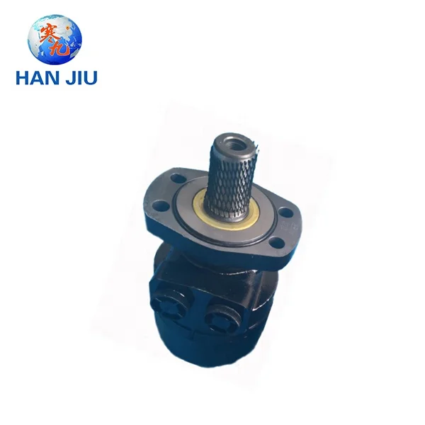
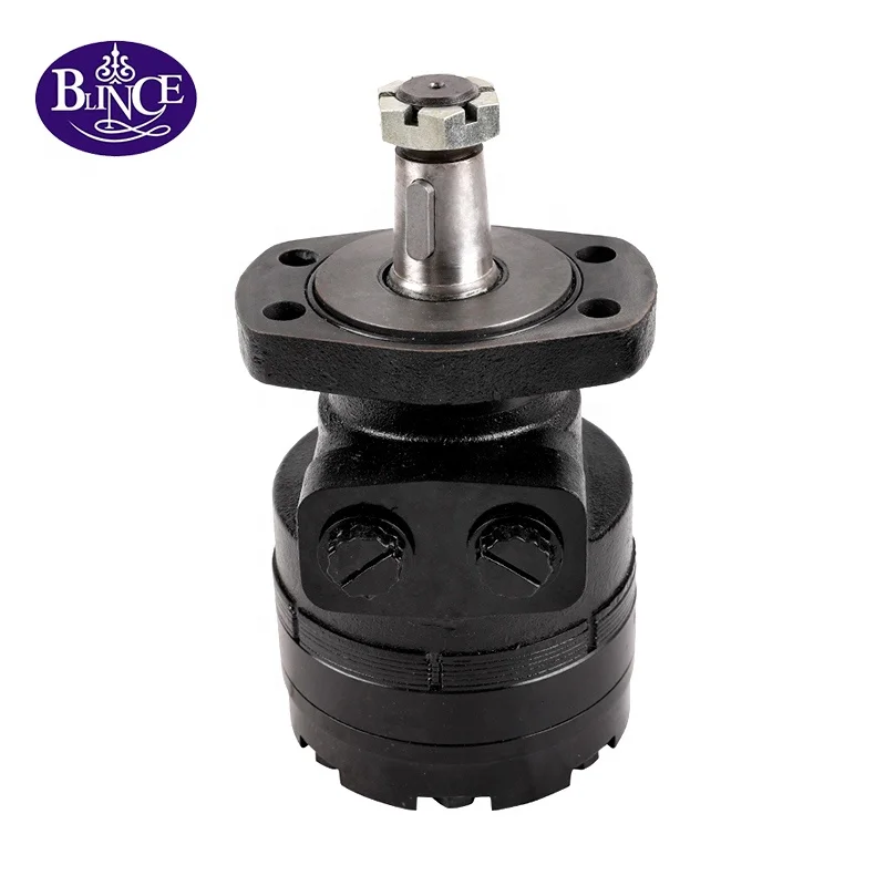
WHITE hydraulic motor is an American brand, under which there are many product series, such as: BK, CE, DR, DT, D9, FD, HB, MP MR, RE, RG, RP, RS, ST, etc. White roller stator hydraulic motor is a product of the American WHITE (White) motor RS series, the product material is made of cast steel, its main features are:
The RS SERIES motors are the most economical models in the WHITE HYDRAULICS product range. But the technology is not low, unlike the power-consuming two-piece rotor pair design with sliding contacts like competitors, the RS series adopts the patented ROLLER STATOR design, seven precision rollers for contact points, reducing friction, providing more power and longer life for your application. Each output shaft is custom ground to maintain tight tolerances between housing and shaft, resulting in high volumetric efficiency. Industry-standard mounting flanges and output shafts allow the RS Series motors to be interchangeable with competitor designs.
Hanjiu has been very familiar with the production and processing of white roller stator hydraulic motor, and has been striving for excellence in the quality of products, and has won many praise from customers, at the same time, Hanjiu has a very high-quality after-sales service, if you have any problems during use, you can contact us, we can repair for you free during the warranty period.
Hydraulic motors (sometimes incorrectly spelled as “hydrolic” motors) convert hydraulic pressure into force that is able to generate great power. They are a type of actuator that converts the pressure of the moving hydraulic fluid into torque and rotational energy.
Hydraulic motors are an important component overall in the field of hydraulics, a specialized form of power transmission that harnesses the energy transmitted by moving liquids under pressure and converts it into mechanical energy. Power transmission is a general term denoting the field of translating energy into usable, everyday forms. The three main branches of power transmission are electrical power, mechanical power, and fluid power. Fluid power can further be divided into the field of hydraulics and the field of pneumatics (translating the energy in compressed gas into mechanical energy).
Arguably, hydraulic power traces back to the beginnings of human civilization. For thousands of years, humans have harnessed the power of moving water for energy. (The most basic “hydraulic” application is harnessing moving water to turn wheels.) For a brief survey of hydraulic history, please refer to our article on Hydraulic Cylinders.
In terms of hydraulic motor development, the middle of the Industrial Revolution proved to be a notable turning point. During that year, English industrialist William Armstrong started developing more efficient applications of hydraulic power after observing inefficiencies in water wheel usage on a fishing trip. One of his first inventions was a rotary, water-powered engine. Unfortunately, this invention failed to attract much attention, but it provided an early model for a rotary actuator based on hydraulic power.
The use of hydraulic systems in general offer several advantages within the overall field of power transmission. Some of those advantages include efficiency, simplicity, versatility, relative safety, etc. These and other advantages are further elaborated on in our article on Hydraulic Pumps.
Hydraulic motors are able to produce much more power than other motors of the same size and for this reason are used for larger loads than electric motors.
When space constrictions are an issue, small hydraulic motors are used. Small hydraulic motors have small stroke lengths; they may be less than an inch.
A major disadvantage of using hydraulic motors is inefficient usage of the actual energy source. Power systems with hydraulic motors can consume large amounts of hydraulic fluid. For example, it is not uncommon for hydraulically-driven machines on construction sites to require 100 or more gallons of hydraulic oil to operate.
Since they are often confused in everyday language, it is important to distinguish between hydraulic motors and hydraulic power packs or hydraulic power units. Technically speaking, an enclosed mechanical system that uses liquid to produce hydraulic power is known as a hydraulic power pack or a hydraulic power unit. These packs, or units, generally include a reservoir, a pump, a piping/tubing system, valves, and actuators (including both cylinders and motors). It is not uncommon, however, to hear a hydraulic motor described as consisting of these components – a reservoir, a pump, etc. However, it is more accurate to describe a hydraulic motor as a part of an overall hydraulic power system that works in sync with these other components. Hydraulic motors are a type of actuating component within an overall hydraulic power system – a component responsible for actually translating hydraulic energy into mechanical energy.
Liquids represent a “median” state between gases and solids on the matter spectrum. Despite this, liquids represent solids far more than gases in an important aspect: they are virtually incompressible. One consequence of this is that force applied to one point in a confined liquid can be transmitted quite efficiently to another point in that same liquid. This reality forms the basis of the mechanical energy that hydraulic systems are able to produce. For a fuller explanation of how hydraulic power works, please refer to our article on Hydraulic Pumps.
It has previously been noted that “Pascal’s Law” applies to confined liquids. Thus, for liquids to act in a hydraulic fashion, it must function with some type of enclosed system. As noticed in the introduction, these “systems” are known as hydraulic power packs and share three main parts—a reservoir, a pump and an actuator—that work together to convert hydraulic energy into mechanical energy.
Hydraulic motors are an integral part of machines that rely on hydraulic power for operation because they actuate and “complete” the process of converting hydraulic energy into mechanical energy. Since hydraulic motors are fairly simple machines that are composed of rotating machinery, they specifically translate hydraulic energy into rotational mechanical energy. The main enclosure and interior components of the motor are made from metal such as steel or iron so they can withstand high pressures and operating speeds. In a sense, motors can be thought of as hydraulic pumps working “backward” or in reverse.
Overall, a hydraulic power unit pumps fluid (usually a type of oil) via a small pneumatic engine from a reservoir and sends it to the motor while regulating fluid temperature. Oil is pumped from the reservoir through an inlet valve to an outlet valve through a series of gears, turning vanes or cylinders, depending on what specific type of hydraulic motor it is. Pressurized fluid creates mechanical energy and motion by physically pushing the motor, causing the rotating components to turn very quickly, and transferring energy to the machinery that the motor is linked to. Typically, not every rotational component is directly connected to producing mechanical energy; for example, in a typical gear motor, only one of the two gears is connected to and responsible for turning the motor shaft. This type of operation directly contrasts with electric engines, in which electromagnetic forces produced by flowing electric current are the response for rotating the motor shaft.
Hydraulic motors, rotary or mechanical actuators which is operated by the conversion of hydraulic pressure or fluid energy to torque and angular displacement.
Driveshaft, a part of the hydraulic motor that delivers or transfers the torque created inside the motor to the outside environment where it is used for lifting loads and other applications.
Vane hydraulic motors have a hydraulic balance that prevents the rotor from sideloading the shaft, with the pressure difference develops the torque as the oil from the pump is forced through the motor.
There are three basic kinds of hydraulics motors: gear, vane and piston type. Each is identified by the design of the rotating component inside. Collectively, the various types of hydraulic motors are optimal for a wide range of specific applications, conditions or usages.
Another common type of hydraulic motor. Radial piston hydraulic motors have pistons mounted around a center shaft that is eccentrically balanced. Fluid causes the pistons to move outward, causing rotation. Axial piston hydraulic motors derive their name from the fact they use axial instead of radial motion, despite their similar design to radial piston motors.
Built into wheel hubs to supply the power needed to rotate the wheels and move the vehicle. A hydraulic wheel motor can operate a single wheel or multiple wheels, depending on the power of the motor and the size of the machine.
Other motors focus on the rotational speed and torque. High speed hydraulic motors convert hydraulic pressure into force at elevated rotations per minute thereby generating large amounts of power. High torque hydraulic motors run at low speeds while operating with increased torque, thus earning the name low speed-high torque (LSHT) motors.
Advances are still being made to hydraulic motors and their various applications. One example is the development of hybrid hydraulic automobiles, which are being developed as an alternative to gas/electric hybrid cars. Hybrid hydraulic vehicles are particularly efficient at reclaiming energy when braking or slowing down.
A type of orbital hydraulic motor, have rollers that are hydro-dynamically supported to minimize friction, ensuring maximum durability and high output at high pressure.
A type of orbital hydraulic motor, are particularly suited for long working cycles at average pressure. Rotor motors are operated by lobes that are fixed and set directly on the stator.
Hydraulic systems and their use are abundant in a wide variety of fields including construction fields, agricultural fields, industrial fields, transportation fields (e.g. automotive, aerospace), various marine work environments, etc. Hydraulic motors are commonly used in machinery that requires strong pressurized actions such as aircraft for raising the wing flaps, heavy duty construction vehicles such as backhoes or crane industrial lifting or for powering automated manufacturing systems. Hydraulics motors are also used in trenchers, automobiles, construction equipment, drives for marine winches, waste management and recycling processes, wheel motors for military vehicles, self-driven cranes, excavators, forestry, agriculture, conveyor and auger systems, dredging and industrial processing.
While hydraulic power transmission is extremely useful in a wide variety of professional applications, it is generally not recommended to use only one form of power transmission. Although it is somewhat counter-intuitive, the maximum benefit of each form of power transmission (electrical, mechanical, pneumatic, and hydraulic) occurs when each form is integrated into an overall power transmission strategy. As a result, it is worthwhile to put in an effort to find honest and skilled hydraulic manufacturers / suppliers who can assist you in developing and implementing an overall hydraulic strategy.
Despite the apparent simplicity of hydraulic systems, engineers and manufacturers must take into account certain variables in order to build an efficient and safe device. The fluid used in the motor or system must be a good lubricant, first and foremost. It should also be chemically stable and compatible with the metals inside the motor. The pump, fluid reservoir and relief valves should be of appropriate power, capacity or strength to allow the motor to perform at optimum levels.
Problems with hydraulic motors can often be traced to poor maintenance, the use of improper fluid within the motor, or improper usage of the motor itself. Some not uncommon causes of motor failure are:
It is important to keep in mind that hydraulic motors are designed to function within certain limits which should not be exceeded. Those limits mainly include torque, pressure, speed, temperature, and load. To give one example, operating a hydraulic motor at excessive temperatures thins hydraulic fluid, negatively affects internal lubrication, and decreases overall the efficiency of the motor. Staying within a motor’s operational limits will preempt unnecessary and needless malfunctions.
In terms of safety, the relative simplicity of hydraulic systems and components (when compared to electrical or mechanical counterparts) does not mean they should not be handled with care. A fundamental safety precaution when interacting with hydraulic systems is to avoid physical contact if possible. Active fluid pressure within a hydraulic system can pose a hazard even if a hydraulic machine is not actively operating.
A container that stores fluid under pressure. Accumulators, the common types of which are piston, bladder and diaphragm, are used as an energy source or to absorb hydraulic shock.
The amount of fluid that passes through a pump, motor or cylinder in a period of time or during a single actuation event, such as a revolution or stroke.

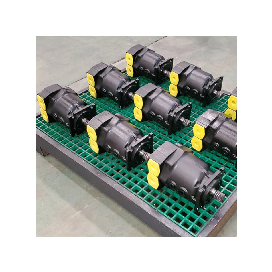
Hydraulic equipment and parts tend to need replacing from time to time and finding the right model can be tricky as well as time consuming. Browse the wide range of roller stator hydraulic motor models on Alibaba.com to find the item you need. The catalog can be filtered according to the type of part you need and also according to safety standards.
Replacing roller stator hydraulic motor components and other mechanical parts is an essential aspect of equipment and machinery maintenance. It also goes a long way in keeping machines functioning effectively and efficiently. You are sure to find what you need among the wide array of parts and products available.
Shop roller stator hydraulic motor components and filter according to features such as motor type and warranty. These products can be shipped anywhere and are available at prices you"ll love. Whether you need a new roller stator hydraulic motor or any other part, Alibaba.com has got you covered. Use the handy filters to browse thousands of reputable wholesales to find the product that matches your business needs.
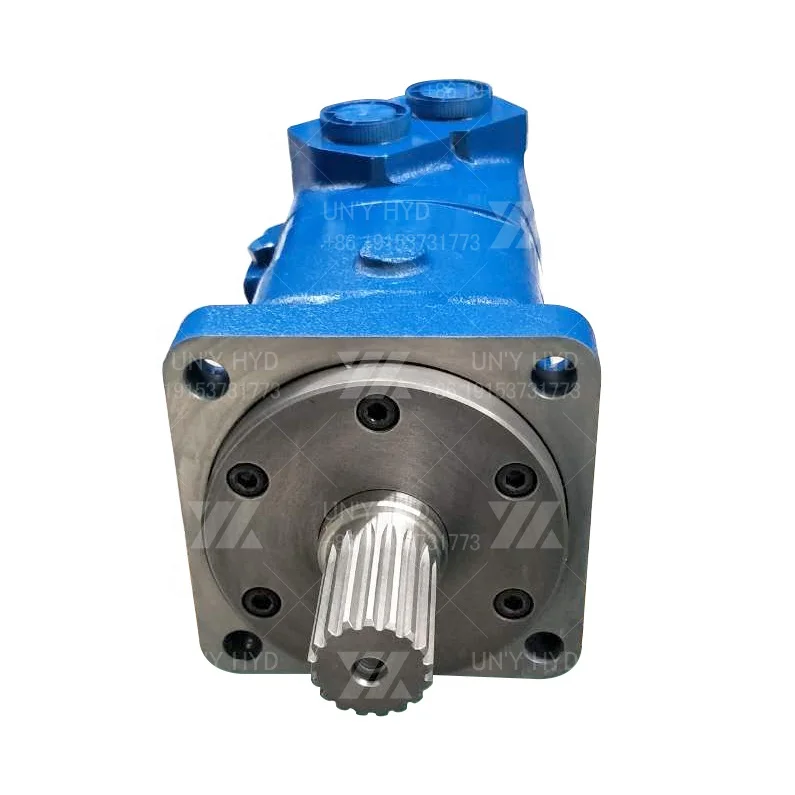
The BMK6 series motors adapt the advanced Rolortorc™ gear set design with disc distribution flow and high pressure. These motors can be supplied with various options for multifunctional operations in accordance with the application requirements. The output shaft tapered roller bearings permit high xial and radial forces offering a smooth operation during low pressure start up and high pressure operation. The low weight, advanced construction design motors are manufactured in accordance with the requirements of the ISO 9000-2000 quality system.

This application claims the benefit of a provisional U.S. patent application entitled HYDRAULIC PUMP WITH ELECTRIC GENERATOR, having a Ser. No. 62/174,242, filed Jun. 11, 2015. The disclosure of this application is hereby incorporated by reference in its entirety.
The present invention relates generally to hydraulic pumps. More particularly, the present invention relates to a hydraulic pump configured to use the rotating shaft of a prime mover configured to operate the pump to also generate electric power.
Hydraulic pumps are often operated at construction or other work sites that do not always have access to electric power. The hydraulic pumps may be operated by a variety of different prime movers. For example, gasoline motors, diesel motors, pneumatic motors, natural gas motors, propane powered motors or any other type of motor may be used to drive a hydraulic pump. In many instances, the prime mover may provide a rotating shaft to the hydraulic pump. The hydraulic pump then has a shaft that connects to the output shaft of the prime mover in order to operate the hydraulic pump.
In some instances, it may be useful to have some electric power available in addition to the mechanical shaft power provided by the prime mover. For example, certain hydraulic valves may be electrically operated or controlled by electronic controller that runs on electricity. In other instances various valves a be moved by electric actuators. In still other instances, other devices may run on electricity forming a desire for electric power to be generated by the energy or rotating shaft of the prime mover. In some instances, generators may not be used to generate electric power because of arcing or sparks that may occur within the generator. For example, in mines where flammable gases may accumulate such generators should not be used. Accordingly, it is desirable to provide a method and apparatus that can use the rotating shaft provided by a prime mover to run both a hydraulic pump and generate electric power.
The foregoing needs are met, to a great extent, by the present invention, wherein in one aspect an apparatus is provided that in some embodiments uses a rotating shaft powered by a prime mover to run both a hydraulic pump and generate electricity.
In accordance with one embodiment of the present invention, a hydraulic pump is provided. The pump includes: a pump shaft adapter configured to rotate and operate the hydraulic pump thereby; a magneto operatively connected to the pump shaft adapter; conductors extending from the magneto connecting the magneto to a power outlet to provide electricity generated by the magneto to the power outlet; and a hydraulic pump housing enclosing both the hydraulic pump and the magneto.
In accordance with another embodiment of the present invention, a method of generating electricity is provided. The method includes: adapting a pump shaft to include an attaching structure; attaching a magneto to the attaching structure; and configuring the magneto to generate electricity when the pump shaft rotates.
In accordance with yet another embodiment of the present invention, a hydraulic pump is provided. The pump may include: a means for transmitting mechanical power configured to rotate and operate the hydraulic pump thereby; a means for generating electrical power operatively connected to the means for transmitting mechanical power; means for transmitting electrical power extending from the means for generating electrical power to a power outlet to provide electricity generated by the means for generating electrical power to the power outlet; and a hydraulic pump housing enclosing both the hydraulic pump and the means for generating electrical power.
FIG. 2 is a front view of a motorized hydraulic pump with part of the housing removed in order to show internal components according to embodiments of the present disclosure.
FIG. 8 is a perspective, partial, enlarged cross-sectional view of a portion of the motorized hydraulic pump according to an embodiment of the disclosure.
The various embodiments in accordance with the present disclosure will now be described with reference to the drawing figures, in which like reference numerals refer to like parts throughout. An embodiment in accordance with the present disclosure provides a motorized hydraulic pump. The motorized hydraulic pump is driven by a prime mover. The prime mover provides energy to run the hydraulic pump in the form of a rotating shaft. In addition to performing pumping operations, the hydraulic pump is capable of generating electricity. Electricity may be used for a variety of purposes including operating hydraulic valves that may receive pressurized hydraulic fluid from the hydraulic pump.
FIGS. 1, 2, and 3 illustrate a motorized hydraulic pump 10 in accordance with the present disclosure. The motorized hydraulic pump 10 includes a prime mover 12. The prime mover 12 illustrated in FIGS. 1-3 includes a gasoline reciprocating engine. However, in other embodiments, a variety of prime movers 12 may be used. For example, the prime mover 12 may be a pneumatic motor, a hydraulic motor, an engine running on propane or natural gas or any other motor that is configured to rotate a shaft.
FIGS. 1-3 illustrate a power generation assembly 14. The power generation assembly 14 is located in between the prime mover 12 and the hydraulic pump 18. The power generation assembly 14 shown in FIG. 1 is covered by a housing 16. In some embodiments, the housing 16 is part of the hydraulic pump 18 such that the power generation assembly 14 is contained within the housing 16 of the hydraulic pump 18. The housing 16 is removed (or, at least, partially removed) in FIGS. 2 and 3 to better illustrate the parts of the power generation assembly 14.
FIG. 2 is an assembled view of the motorized hydraulic pump 10 with the housing 16 removed. FIG. 3 is a partially exploded view of the motorized hydraulic pump 10 where the prime mover 12 and the hydraulic pump 18 are intact but separated from each other. As shown in FIGS. 2 and 3, the prime mover 12 has a drive shaft 22 that extends down below the prime mover 12 toward the power generation assembly 14. The power generation assembly 14 may be a magneto 20. The magneto 20 may include a rotor 21 and a stator assembly 26 which will be discussed in further detail later below. The magneto 20 is attached to an adapted pump shaft 24 which is also connected to the drive shaft 22 of the prime mover 12. In some embodiments, it is the adapted pump shaft 24 which is attached to the power generation assembly 14 and also drives the hydraulic pump 18.
FIG. 4 is a perspective view of the adapted pump shaft 24. FIG. 5 is an end view of the adapted pump shaft 24 having a broken out portion 44 which allows better illustration of some of the aspects of the adapted pump shaft 24 described below. With respect to FIGS. 4 and 5, the adapted pump shaft 24 includes a shaft portion 28 terminated at one end with a flat end portion 30.
In some embodiments, the flat end portion 30 is configured to engage with components of the hydraulic pump 18 to drive the hydraulic pump 18 (See FIGS. 1-3 for the hydraulic pump 18). The adapted pump shaft 24 may have a larger diameter portion 32 which has a larger diameter than the shaft portion 28. The larger diameter portion 32 may include a set screw hole 34 which, in some embodiments, may be threaded. The screw hole 34 may be used to allow a screw to enter the screw hole 34 and urge against the shaft 22 to better keep it in place within the adapted pump shaft 24.
The adapted pump shaft 24 may be particularly adapted in order to both drive the hydraulic pump 18 and the rotor 21. In this regard, the adapted pump shaft 24 may include attaching structure such as, but not limited to, a flange 36 having connecting holes 38. The flange 36 and connecting holes 38 may allow the adapted pump shaft 24 to attach to the rotor 21 which will be described in additional detail below. The adapted pump shaft 24 may also define an opening 40. In some embodiments, the opening 40 may be encompassed about by a raised lip portion 41. Furthermore, in some embodiments, the opening 40 may also include a keyway 42 which may be dimensioned to engage with a key located on the drive shaft 22 in order to provide a positive rotational connection between the drive shaft 22 coming from the prime mover 12 and the adapted pump shaft 24.
FIG. 6 is a partial cross-sectional view of the motorized hydraulic pump 10. The drive shaft 22 is shown extending from the prime mover 12 through the rotor 21 and stator assembly 26 and connecting to the adapted pump shaft 24. The attaching bolts or fasteners 46 are shown extending through attaching holes 47 in the rotor 21 and the connecting holes 38 in the adapted pump shaft 24. In this manner, the flange 36 of the adapted pump shaft 24 is secured against the mounting surface 49 of the rotor 21.
The rotor 21 has a receiving hole 48. In some embodiments, the receiving hole 48 has been modified or formed so that it is dimensioned to permit the raised lip portion 41 of the adapted pump shaft 24 to extend into the rotor 21. In some embodiments, the receiving hole 48 is modified from a tapered shape common to off-the-shelf parts and is squared off as shown. The adapted pump shaft 24 sits upon a bearing 51 and extends into the hydraulic pump 18.
FIG. 7 is a partial enlarged cross-sectional view of the power generation assembly 14. The rotor 21 and the stator assembly 26 are shown with the drive shaft 22 extending through both the rotor 21 and the stator assembly 26. A rectifier 50 is illustrated as attached to the housing 16. The rectifier 50 is secured to the housing 16 by holding screw 52. In other embodiments the rectifier 50 may be mounted in a different manner than what is shown and described herein while still being in accordance with the disclosure. The rectifier 50 may include various attachment points 54 for receiving wires 53 extending out of the stator assembly 26 (as seen in FIG. 6).
As shown in FIG. 8 which is a partial cross-sectional perspective view of the power generation assembly 14 the magneto 20 operates by a stator assembly 26 having coils 56 made of coiled wires or conductors remaining stationary while the rotor 21 including magnets rotates around the coils 56. In this manner, electricity is generated within the conductors in the coils 56 and the electricity flows out of the wires 53 as shown in FIG. 6. Magnetos 20 are well known and will not be described in additional detail here. One of ordinary skill in the art after reviewing this disclosure will understand that magnetos 20 having different construction than that shown and described herein may be used in accordance with the present disclosure.
In a nonlimiting example embodiment, the magneto rotor 21 and stator assembly 26 may be obtained from Universal Parts 7300 Bryan Dairy Road, Seminole, Fla., 33777. The rotor 21 is identified by part number 164-191 and the stator assembly 26 is identified by part number 164-289.
An object of this invention is to provide a rotary fluid pressure device including a gerotor having a fixed stator inside of which is an orbiting and rotating rotor. The rotation of the orbiting rotor member provides the output or input at the shaft member. This rotor has a continuous ring valve on one side and both of the supplies of intake and exhaust pressure fluid are on the opposite side. A star-pointed annulus increases commutation fluid flow. The second embodiment shows again a fixed stator with an orbiting rotor with the rotating component of the rotor used at the output shaft; but in this embodiment the intake is on the internal diameter of one side of the rotor member with balanced area grooves in communication with the first named intake and exhaust grooves on the opposite side of the rotor so as to provide a hydraulically balanced rotor.
The present invention reduces the number of manufacturing operations necessary to make hydraulic pressure devices. The devices made in accord with this invention are simple, reliable and efficient.
FIG. 21 is a sectional view of the manifold plate of the bilateral ported hydraulic device of FIG. 20 taken generally along lines 21--21 of that FIGURE.
FIG. 23 is a sectional view of the manifold plate of the inverse valved hydraulic device of FIG. 22 taken generally along lines 23--23 of that FIGURE.
Those familiar with this type of apparatus will understand that while the present invention is being described as a pump using a fluid inlet and a fluid outlet, nevertheless, the same structure may be used as a motor by merely reversing the fluid inlet and outlet so that the high pressure fluid now enters at what was previously the inlet and the device operates as a motor.
The gerotor set 22, best seen in FIGS. 1 and 4, comprises an internal toothed member 27 which is a stator inside of which a coacting externally toothed member 28, a rotor, which rotates about its own axis A as seen in FIG. 4, but which is eccentric relative to the center of the stator 27 by the distance shown between A and B, on the line of eccentricity C, and the rotor orbits about the center B. During this movement of the rotor and stator a series of cells 29 and 29a form a series of cells of constantly changing size between the rotor and stator, the size of the cells becoming greater on one side of the line of eccentricity, and the cell size becoming smaller on the opposite side. In FIG. 4 the minimum size cell at 29a approaches zero. The rotor rotates in the direction of the arrow shown in FIG. 4. The rotor has two flat axial end surfaces.
The internal teeth 27a on the stator 27 are provided by cylinders 27a inserted in recesses 27b over 180° in circumference so as to maintain the cylinders 27a in the positions shown in FIG. 4. It will be understood that the cylinders 27a terminate at the level of the opposite faces of the stator 27. The rotor 28 has external teeth which are formed to fit almost exactly between the internal teeth of the stator, as shown in FIG. 4. The rotor 28 has an open center 35 surrounded by a sealing strip 36 which is uninterrupted circumferentially and laterally outside of which is an annular liquid intake passageway 37. The axis of rotation for the wobble stick 38 is marked A" in FIG. 4. The axis of rotation for the orbiting movement of the wobble stick 38 relative to the stator is indicated at B in FIG. 4. The line C passing through A and B is herein indicated as the line of eccentricity. The movement of the rotor herein described is as indicated by the arrow D in FIG. 4. During this rotation the cells 29 on the lefthand side of the line of eccentricity increase in size gradually while the cells 29 on the righthand side of the line of eccentricity gradually decrease in size as indicated in FIG. 4. The rotor functions as the main valve for the device. Six travel passageways or holes 37a are evenly spaced around the annulus 37 extending linearly through the rotor parallel to the axis of the rotor. These project radially inwardly from the annulus or annular channels 37 as seen at 37b, in one embodiment this being about 1/8 of an inch projection. The other travel passageway is generally on the central axis of the rotor, in the structure disclosed around the wobble stick-rotor device connection. There are sufficient openings in this type of drive connection that fluid flow is relatively unimpeded by the spline-gear interfaces. The transfer channel 34 communicates with the annular channel as the device is operated.
This embodiment has been described as a pump utilizing the drive shaft 44 for the attachment of power which would cause intake of lower pressure fluid at 30 and exhaust of higher pressure fluid at 31. As previously explained, reversing the connections 30 and 31 will cause the device to operate as a motor producing power on the drive shaft 44.
The operation of the first embodiment as a pump will now be described. Power is supplied to the protruding left end of the drive shaft 44 as seen in FIG. 1. This rotates the shaft, the wobble stick 38, the rotor 28, and also causes the rotor to orbit about the stator 27. This causes the cells 29 to the left of the line of eccentricity C to gradually increase in size causing a suction at the intake 30. The cells 29 on the righthand side of the line of eccentricity C in FIG. 4 are also caused to progressively decrease in size thus causing the fluid under increased pressure to exhaust at the outlet 31. The incoming fluid from intake 30 passes through the annular channel 32, the passageways 33a to the annular channel 34, then through the rotor 28 through the annular channels 37 and the cylindrical holes 37a, then through the double trapezoidal openings 40 in the manifold 23, then through the passageways 41a and 42 in the manifold and through the openings 41 in the manifold and rotor and thus into the expanding cells 29. Other cells 29 are exhausted back through other openings 41 and other passageways 42 and 41a and other double trapezoidal openings 40 in the manifold into the open center 35 of the rotor. The fluid then flows over and around clearances in the wobble stick-rotor drive connection, cooling and lubricating it, through the opening 21a, through the hollow portion 44a of the shaft and through openings 45 and 46 and thus out through the outlet 31.
The main housing portion 60 has secured to it a wear plate 61, a gerotor set 62, a manifold 63 and an end cap 64, all secured rigidly together by a plurality of bolts 65 extending from the righthand end of the device as seen in FIG. 8 into threads in the main housing portion 60. The main housing portion has an air intake 66 connected by a passage 67 through the housing portion 60 with a continuous annulus chamber 68, which communicates with a plurality of radial openings 69 which lead inwardly to a hollow portion 70a of a drive shaft 70 which is rotatably mounted in the housing portion 60. An elongated rigid wobble stick 71 has a spline connection 71a at one end with the drive shaft 70 and another spline connection 71b at the opposite end with the rotor member of the gerotor set 62. The spline connections 71a and 71b are so shaped as to permit the rotation of the wobble stick while at the same time permitting it to follow the orbiting movement of the rotor in the stator as will presently appear.
The gerotor 62 is best seen in FIG. 9. It comprises a stator 62a which has a plurality of internally extending teeth formed partly by direct formation in the stator but also in part by six cylindrical members 62b which are firmly held in recesses 62c which extend for a distance greater than the diameter of each of the cylinders 62b so that they are held firmly in the position shown in FIG. 9. A rotor 72 is shown having a plurality of externally extending teeth 72a which are shaped to fittingly coact with the internally extending teeth 62, 62a and 62b, these external teeth being one less in number than the internal teeth previously described. The rotor has an axis E which is eccentric relative to the axis F of the stator and the line G passing through points E and F is herein designated as the line of eccentricity. The rotor is provided with a generally annular ring 73 forming part of the intake passageway for fluid. This passageway is concentric around the axis E. Inside the annular ring 73 is a circular opening 74, also concentric, for the exhaust of fluid from the rotary fluid pressure device.
Referring now to FIGS. 9, 10 and 11, FIG. 11 shows the face of the manifold toward the gerotor structure 62. Centrally there is the exhaust opening 75 which communicates with the exhaust opening 74. In the next circle, and concentric, are seven rotor communicating openings 76, and in an outer concentric circle are seven passageway openings 77 so positioned that they cooperate circumferentially with the cells 80 which are formed in changing fashion between the rotor and the stator as seen in FIG. 9.
A balancing ring 86 is on the opposite side of the rotor from the annular ring 84. Small passages 87 through the rotor connect the balancing ring 86 to the opening 74. The balancing ring 86 equalizes the hydraulic pressure on the rotor 72.
It should now be apparent how the operation of this device as shown in FIGS. 8-11 operates. Power is applied to the shaft 70 causing the rotor 72 to rotate in the stator 62a in the direction of the arrow shown in FIG. 9. The intake flow is from the inlet 66 through passageways 67 and 68, then through the hollow shaft portion 70a and through the central opening 61a in the wear plate. Then the flow is through passageways 82 and 83 to the annular passageway 84 which opens toward the manifold 63. Then the flow passes through an opening to passageway 76 on one side of the eccentricity line G through the manifold passages 78, 79 to one of the openings 77 which is in communication with one of the cells 80 between the rotor and stator. Meanwhile, one of the cells 80 on the other side of the eccentricity line G communicates back to the appropriate passageway 76 and back through the manifold 63 to the exhaust passageways 74, 75 and 85 to exhaust.
FIG. 20 is of a bilateral ported hydraulic device. In this device the inner travel passageway instead of running through the open center 35 of the rotor doubles back through a series of holes 100 in the manifold plate 23B to exit the gerotor device through port 101.
FIG. 22 is of an inverse valved hydraulic device. In this inverse valved device an outer ring channel 103 on one side of the rotor 28A connects through a diagonal passageway 104 to the open center 35 of the rotor. A star shaped annulus 34 communicating with the outer ring channel 103 connects the fluid passage to one of the fluid ports 30. The other fluid passage is a second ring channel 105. Another star-shaped annulus 106 communicating with the second ring channel 105 connects this fluid passage to the other of the fluid ports 107. This annulus 106 is on the manifold plate 23C between openings 40 and 41. See FIG. 23. (These openings 40 and 41 are connected together respectively by a series of channels 108 on the opposite side of the manifold plate 23C.) A series of holes 109, the location of which is not critical, extend from the annulus 106 through the manifold plate 23C and through the channel closure plate 110 to connect with cavity 111. The port 107 is connected to the cavity 111.
FIG. 24 is of a manifold plate ported hydraulic device. In this device both the porting commutation and the valving occur between a single surface of the rotor and the manifold plate 23D.
Passages 37A and the other ring channel 37 hydraulically balance the rotor for fluid pressure in the ring channel 37. The opposite end of the open center of the rotor hydraulically balances the open center fluid passage.
The actual porting in the manifold ported hydraulic device of FIG. 24 is accomplished through the use of a series of successive plates 115-118 and 23D. Each of the plates is designed for ease of individual manufacture. See FIGS. 25-28. During assembly each plate is located in proper sequence in respect to the other plates to together form the porting passages of the device.
The cylinder 1(C1) and cylinder 2(C2) recesses are connected through passages in the power steering unit 127 and high pressure hydraulic hoses to opposing sides of a double acting hydraulic steering cylinder (all not shown). The pressure 1(P1) and pressure 2(P2) recesses are connected through passages in the power steering unit 127 and high pressure hydraulic hoses to the high pressure outlet of a hydraulic pump driven by an engine (all not shown). The return 1(R1) and return 2(R2) recesses are connected through passages in the power steering unit 127 and high pressure hydraulic hoses to the low pressure inlet of the hydraulic pump (all not shown).


 8613371530291