
rotary vane hydraulic pump free sample
This article aims to describe the main features of the vane pump technology, how it works, its advantages and disadvantages, and where it is most commonly used. Finally, we will briefly mention the Fluid-o-Tech vane pumps.
Rotary vane pumps are a type of positive displacement pump. Like all positive displacement pumps, the flow rate is always directly proportional to the speed.
Vane pumps are available with different types of vane: sliding, flexible, oscillating, rotating, and external vanes. The vane pumps are known for their dry-priming, easy maintenance, and good suction characteristics throughout the life of the pump.
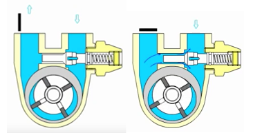
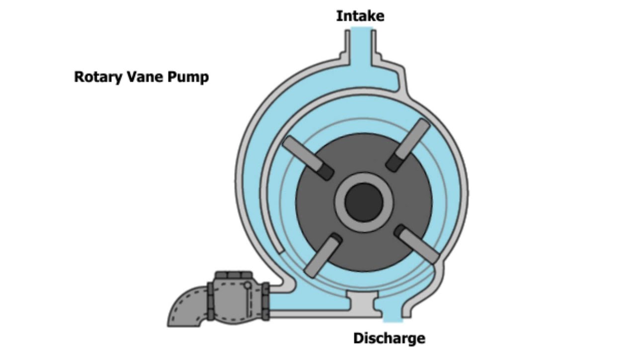
A splined rotor is supported eccentrically in a cycloidal cam. The rotor sits close to the cam wall to form a crescent-shaped cavity. The rotor is sealed in the cam by two side plates. The vanes or blades fit into the rotor cavities. When the rotor rotates and fluid enters the pump, the centrifugal force, the hydraulic pressure, and/or the pushrods push the vanes towards the housing walls. The tight seal between the vanes, the rotor, the cam, and the side plate makes this technology powerful for good suction, which is common to the vane pumping principle.
The housing and cam force the fluid into the pumping chamber through holes in the cam (small red arrow on the bottom of the pump). The fluid enters the pockets created by the vanes, the rotor, the cam, and the side plate.
As the rotor continues to spin, the vanes sweep the fluid to the opposite side of the crescent where it is squeezed through the cam discharge holes as the vane approaches the point of the crescent. The fluid then exits through the discharge port.
The rotary vane pump is very versatile and can be used in a variety of sectors and applications, from dosing to transferring and repressurizing fluids. Depending on the choice of materials, rotary vane pumps can handle a wide range of clean fluids.
Fluid-o-Tech is able to supply a wide range of rotary vane pumps covering a variety of applications in different sectors. In stainless steel, low-lead brass, technopolymer, direct coupled, magnetic or electromagnetic drive at variable speed, our pumps cover a flow rate range from 30 to 2200 l/h at pressures up to 18 bar. The built-in safety valve, available on request, limits the pressure to protect the pump and the hydraulic circuit.
The Fluid-o-Tech rotary vane pumps, WRAS or NSF certified for use with potable water, are the reference choice in the market of espresso machines and beverage dispensers for professional use.
Avoid any downtime at your construction site with the range of mini rotary vane pump from Alibaba.com. You can check out the fully-stocked parts at Alibaba by manufacturer and model and affordable wholesale prices. The wholesale mini rotary vane pump collection of spare parts from China’s wholesaler, Alibaba, fits well with a wide range of heavy-duty equipment, from bulldozers, excavators, and hammers, among others. Plus, you can find parts for your tractors, skid steer loaders, wheel loaders, backhoe loaders, and crawler dozers.
If you have a limited cash allocation, the used or remodeled parts will go a long way in accommodating your budget. Alibaba’s mini rotary vane pump and tools make it easy to replace, modify and enhance your equipment for their optimal performance. For electrical and mechanical applications, you can find your match at Alibaba.com for everything you need to make your vehicle perform better. Get engine oils, batteries, hydraulic parts, transmissions, injectors, hoses, and starters from the mini rotary vane pump at Alibaba.com.
The new parts from manufacturers have warranties, and you can buy them by matching the part numbers. Such parts, including hoses, plugs, or filters, will help you quickly deal with downtime on site. The used parts, on the other hand, sell for a lower price. Remember, Alibaba partners with sellers who have certificates of operation. So, you can use these second-hand mini rotary vane pump to get your heavy machine running. You can also get rebuild models from the collection at Alibaba.com. These are sustainable choices that use recycled materials and perform as well as the new parts. And depending on your seller of choice, you might get a warranty to accompany them.

Rotary-vane pumps are positive displacement machines capable of handling lubricating and other low-viscosity fluids in low to medium volumes at low pressures and, in some applications, relatively viscous fluids. Sometimes called carbonator pumps for their use in making carbonated soft drinks, the design has traditionally been used as well in automotive applications. They have an ability to develop a good vacuum and are often used to transfer LNG as well as some solvents. Their various permutations are described here along with a discussion of their operation and common applications. For information on other pumps, please see our Pumps Buyers Guide.
These pumps combine an eccentric ring and a rotor fitted with slots. The slots hold the vanes which are capable of moving radially as the rotor turns in the ring. As the vanes revolve past the suction port, they move outward, creating a volume defined by consecutive vanes, the rotor, and the ring wall. This volume draws fluid in and is then sealed off as it moves past the suction port. On the discharge side, the combined eccentricity of ring and rotor pushes the vanes into the slots, decreasing the volume and forcing the fluid out through a discharge port. Both suction and discharge ports, or galleys, are often kidney-shaped and fill from the sides.
Vanes are often constructed from carbon graphite to minimize wear where low-lubricity fluids are handled. Centrifugal force and fluid pressure are the common means of extending the vanes out to the ring walls but positive methods of extending them such as rods are used in certain designs. The vanes themselves are able to compensate for wear and most designs allow for easy vane replacement, making sliding-vane pumps low maintenance.
Another design employs pivoting vanes which swing outward through centrifugal force to form volumes which decrease as they move past the discharge openings. External-vane pumps are also produced.
Sliding-vane pumps can be fixed-output designs or they can be manufactured with an ability to vary the eccentricity between rotor and ring. This gives variable-rate control from a constant input rpm. Pressure-compensated pumps are used in many fluid-power applications.
Like the sliding-vane pump, the flexible-vane pump relies on eccentric motion developed between a revolving rotor and a fixed ring to move fluid between suction and discharge ports. Instead of slots and rigid vanes, though, the flexible vane pump employs vanes that are molded from a flexible material which deforms as the rotor makes its circuit. This produces cavities which expand on the suction side and collapse on the discharge side. The design is useful for moving fluids that contain particles or solids as there are no critical internal clearances where such particles might lodge. Impellers are manufactured from various rubber compounds including EPDM and silicone for compatibility with a variety of products. Flexible-vane pumps are considered to be low shear.
As mentioned, soda dispensers use sliding-vane pumps to move water into pressurized CO2 tanks. Commercial espresso machines use them as well to force heated water through densely packed espresso grinds. Vane pumps are considered to be differential-pressure pumps, meaning they can pressurize a fluid entering the pump suction at higher than atmospheric pressure, as might be the case for an espresso machine that is hard-piped to the water supply. Home espresso machines typically use cheaper piston pumps designed to draw water up from built-in tanks.
Automakers use vane pumps to pressurize the low-viscosity hydraulic fluid found in power-steering systems, for which the original Vickers pump was developed. They are used both as fixed- and variable-output units in automatic transmissions. Sliding-vane pumps are best suited to low-viscosity fluids that are free of particulates. External-vane pumps are sometimes deployed to handle fluids containing solids.
Sliding-vane pumps are regularly used in refineries, terminals, etc. for pumping oils, solvents, paints, and coatings, etc. Rotary-vane technology is applied to hand-cranked pumps for manual transfer and similar operations. In recent years, micro-hydraulic systems for use in personal-assist devices have brought about the need for miniature rotary-vane pumps.
Flexible-vane pumps are heavily employed for food, beverage, and pharmaceutical services as their low-shear designs allow them to move cosmetics and similar creams without affecting their qualities or pump fluids with solids (such as yogurt) without damage. The low-shear design is also applied for marine bilge pumping and water-based glue making, for example. Flexible-vane pumps produce only low to moderate pressures, and material viscosity has a role in just how high of a pressure can be attained.
Flexible-vane pumps have very good self-priming characteristics and can be used for tank stripping and similar operations without requiring valves or hand priming. They are reversible as well, making them handy for clearing intake lines of high-viscosity products. Flexible-vane pumps offer a relatively low-cost solution for pumping solids and shear-sensitive products over other low-shear designs such as rotary-lobe pumps.
Housings can be made in stainless steel for sanitary service or bronze for marine service but ductile iron is used where possible because of its self-lubricating characteristics. The pumps are available both as close-coupled and as sealless, magnetically-coupled units. Vane pumps fall about midway between economical gear pumps and expensive piston pumps.
Finally, while rotary, positive-displacement pumps are capable of pumping water, their primary application is for oils and viscous liquids because of the need to keep rubbing surfaces lubricated and the difficulty in sealing very thin fluids. For most applications where water is the media, the centrifugal, or dynamic-displacement, pump has been the clearer choice. Vane pumps work well with low-viscosity fluids and are used to pump water to moderate pressures in several specific applications as noted here.
This article presented a brief discussion of vane pumps including the common types and how they work. For more information on related products, consult our other guides or visit the Thomas Supplier Discovery Platform to locate potential sources of supply or view details on specific products. Additional information on gear pumps may also be found on the Hydraulic Institute webpage.

Efficient- Up to 30% more energy-efficient than comparable rotary vane vacuum pumps, low operating costs, high uptime, reduced heat emission, optimized heat direction

Efficient- Up to 30% more energy-efficient than comparable rotary vane vacuum pumps, low operating costs, high uptime, reduced heat emission, optimized heat direction

Unfortunately, it is not possible to retrofit solvent recovery glassware to our pumps. However we do offer controllers that will work with your diaphragm or rotary vane vacuum pump, regardless of manufacturer.
Because the CVC3000 is designed to be operated with a huge span of vacuum pumps, we offer several different valves to go with it. Having a separate valve and vacuum fitting also allows the controller and valve to be located at their optimal positions for best vacuum control, and not just what is convenient for the controller. Additionally, while controllers that shut the pump off to control vacuum are less expensive, they can allow condensation inside the pump and produce additional strain on the pump upon restart.
It depends. For certain applications, like freeze drying, diaphragm pumps can not achieve the ultimate vacuum required to perform the task. In these cases, we can suggest our low-maintenance RC6 chemistry-Hybrid pump as an alternative. However, for most laboratory applications, selecting the best pump for an application requires a bit more information that just telling which rotary vane pump you used to use, so that you don"t pay more than you need to, but get the correct accessories as well. Try our Vacuum Pump Selection Guide, or call our Customer Service department to get a customized recommendation for your application.
For example, dry ice has a temperature of -78.5°C. Acetone has a vapor pressure at that temperature of approximately 0.5mbar. So, when operated with a two-stage rotary vane pump, with an ultimate vacuum of approximately 0.001mbar, a dry ice trap would not be effective. A better choice would be liquid nitrogen, with a temperature of -196°C.
Of course, a dual-stage rotary vane pump would be overkill to evaporate acetone. If a single-stage diaphragm pump, with an ultimate vacuum of 70mbar was used to evaporate acetone, a dry ice trap would be considerably more effective.
To know whether your cold trap is being effective or not, the efficiency can be calculated by weighing your sample before and after drying to determine the mass of the evaporated solvent. This can be compared to the mass of the liquid collected in the cold trap. All of the solvent that is not collected in the cold trap can be assumed to enter the pump. In the case of a rotary vane pump, it can be assumed to be contaminating the oil.
The number one enemy of a rotary vane pump in a laboratory is vapors from the application. These vapors can condense in the pump oil, and cause corrosion, or change the lubricating qualities of the pump oil. To best ensure the quality of your pump oil:Warm up the pump before use.By warming up the pump, and the oil inside of it, condensation is reduced. A warm pump also performs it"s best. A half hour of warm up time is optimal.
Avoid particulates. Particles entering the pump can score the walls of the pump, reducing it"s efficiency. Additionally, the particles created by scoring of the pump can also cause damage, setting off a chain of events to catastrophic failure.
Never block the pump outlet. Back pressure on the pump reduces its efficiency, and can cause serious internal damage. We do not recommend the mounting of any aftermarket accessories on a pump, except for original manufacturer equipment oil mist filters.
After use, run the pump with the inlet blocked and the gas ballast open. This helps purge any condensed vapors in the pump oil. A half hour is usually sufficient.
Check and maintain regularly. This includes, but is not limited to monitoring of oil level and color, and regular changes. Periodic measurement of pump performance can help prevent catastrophic failure.

A rotary vane pump is a type of positive-displacement pump that consists of vanes mounted to a rotor that rotates inside a cavity. In some cases these vanes can have variable length and/or be tensioned to maintain contact with the walls as the pump rotates.
The simplest vane pump has a circular rotor rotating inside a larger circular cavity. The centres of these two circles are offset, causing eccentricity. Vanes are mounted in slots cut into the rotor. The vanes are allowed a certain limited range of movement within these slots such that they can maintain contact with the wall of the cavity as the rotor rotates. The vanes may be encouraged to maintain such contact through means such as springs, gravity, or centrifugal force. A small amount of oil may be present within the mechanism to help create a better seal between the tips of the vanes and the cavity"s wall. The contact between the vanes and the cavity wall divides up the cavity into "vane chambers" that do the pumping work. On the suction side of the pump the vane chambers are increased in volume and are thus filled with fluid forced in by the inlet vacuum pressure, which is the pressure from the system being pumped, sometimes just the atmosphere. On the discharge side of the pump the vane chambers decrease in volume, compressing the fluid and thus forcing it out of the outlet. The action of the vanes pulls through the same volume of fluid with each rotation.
Multi-stage rotary-vane vacuum pumps, which force the fluid through a series of two or more rotary-vane pump mechanisms to enhance the pressure, can attain vacuum pressures as low as 10−6 mbar (0.0001 Pa).
Vane pumps are commonly used as high-pressure hydraulic pumps and in automobiles, including supercharging, power-steering, air conditioning, and automatic-transmission pumps. Pumps for mid-range pressures include applications such as carbonators for fountain soft-drink dispensers and espresso coffee machines. Furthermore, vane pumps can be used in low-pressure gas applications such as secondary air injection for auto exhaust emission control, or in low-pressure chemical vapor deposition systems.
Rotary-vane pumps are also a common type of vacuum pump, with two-stage pumps able to reach pressures well below 10−6 bar. These are found in such applications as providing braking assistance in large trucks and diesel-powered passenger cars (whose engines do not generate intake vacuum) through a braking booster, in most light aircraft to drive gyroscopic flight instruments, in evacuating refrigerant lines during installation of air conditioners, in laboratory freeze dryers, and vacuum experiments in physics. In the vane pump, the pumped gas and the oil are mixed within the pump, and so they must be separated externally. Therefore, the inlet and the outlet have a large chamber, perhaps with swirl, where the oil drops fall out of the gas. Sometimes the inlet has louvers cooled by the room air (the pump is usually 40 K hotter) to condense cracked pumping oil and water, and let it drop back into the inlet. When these pumps are used in high-vacuum systems (where the inflow of gas into the pump becomes very low), a significant concern is contamination of the entire system by molecular oil backstreaming.
One of the major advantages of the vane pump is that the design readily lends itself to become a variable-displacement pump, rather than a fixed-displacement pump such as a spur-gear (X-X) or a gerotor (I-X) pump. The centerline distance from the rotor to the eccentric ring is used to determine the pump"s displacement. By allowing the eccentric ring to pivot or translate relative to the rotor, the displacement can be varied. It is even possible for a vane pump to pump in reverse if the eccentric ring moves far enough. However, performance cannot be optimized to pump in both directions. This can make for a very interesting hydraulic-control oil pump.
A variable-displacement vane pump is used as an energy-saving device and has been used in many applications, including automotive transmissions, for over 30 years.
Vane pumps are a type of rotary positive displacement pump. A set of paddle-like vanes, mounted radially on a cylindrical rotor, create a number of compartments in which fluid can be trapped and transported through the system. The vanes maintain a close seal against the wall of the pumping chamber preventing fluid from leaking back across the pump. Vane pumps are particularly useful for pumping thin liquids at high pressures. The pumps give low pulsation, accurate flows and have hardened components to resist wear and extend pump life.
During a rotation cycle, the volume between adjacent vanes changes because of the rotor’s eccentric mounting position. This creates the pumping action. There are two main types of vane pumps: sliding vane and flexible vane (see Figure 1):
In a sliding vane pump, the vanes are fitted into radial slots in a cylindrical rotor. When the pump is stationary, the vanes rest in their slots. However, when the shaft rotates at sufficient speed (about 700 rpm) the vanes travel outwards under centrifugal force, maintaining close contact with a perforated cam ring around the casing wall. The vanes may also be spring-loaded to ensure contact even when the pump is stopped. Any wear occurring at the edge of the vanes is compensated by further extension.
In a flexible vane pump, the rotor, or impeller, is made from a flexible material, shaped with several supple lobes that maintain contact with the perforated cam ring and pump casing. The rotor is offset and slightly larger than the pump casing so the vanes are compressed at the ‘short’ side of the cycle and expand again at the opposite side as they conform to the internal shape of the pumping chamber. This action creates separate compartments between the vanes, expanding at the pump inlet to create suction and compressed at the outlet causing discharge. Some wear on the rotor’s lobes can be tolerated since it is larger than the pump casing.
Vane pump casings can be balanced, unbalanced or variable. The pumps shown in Figure 1 are unbalanced designs since the rotor is offset: the centre of the drive shaft and the centre of the pump casing are not aligned. Pressure differences between the inlet and outlet can cause vibrations and increased wear on the drive shaft bearings. In a balanced design, the centre of the pump casing and the rotor coincide (see Figure 2). To achieve this, and still create the same functionality, the pumping cavity is elliptical rather than circular. Pairs of inlets and outlets on opposite sides of the pump also cancel out any pressure imbalances. In a variable design, the dimensions of the pumping chamber can be varied. This feature allows the discharge rate of the pump to be adjusted.
There are several other designs including external vane pumps. In these, the vanes (flexible or rigid) are fitted into the pump casing instead of the rotor. Pumps of this type are preferred for handling fluids containing solids.
Vane pumps are ideal for pumping low to medium viscosity liquids, including those with entrained gases, and can give an accurate, smooth, low pulsation output. With a varying feed pressure, a vane pump will continue to provide a constant flow. They are especially noted for their dry priming, ease of maintenance, and good suction characteristics over the lifetime of the pump. There is no internal metal-to-metal contact and the pumps self-compensate for wear through vane extension. Vane pumps can handle thin liquids at relatively high pressures and can run dry for short periods. They are also reversible so can be used to load and unload a vessel and also ensure liquid is fully recovered from delivery hoses.
The efficiency of a vane pump decreases with increasing fluid viscosity so they are not suitable for high viscosity liquids. The maximum differential pressure for vane pump operation is about 15 bar. Flexible vane pumps can be used to pump liquids containing solids but sliding vane pumps are more suitable for clean liquids. Flexible vane pumps can be used with slurries but it may be necessary to limit pump speed to restrict wear. Vane pumps are prone to damaging wear when used with feeds containing abrasives and usually require protection by a suction-side filter.
Unless the pump uses a magnetic coupling, the drive will require a shaft seal of some type and this can be a source of leaks. Mechanically, vane pumps are complex with many parts but any maintenance to replace worn vanes or shaft seals is generally straightforward and inexpensive. As with most positive displacement pumps, some form of pressure relief is necessary in case of a downstream blockage. Vane pumps with multiple vanes will give essentially pulse-free flow but pulsation may be problem at low speeds with pumps fitted with only one or two vanes.
Sliding vanes are often made of materials capable of self-lubrication so they can slide easily inside their rotor slots and against the casing. They are available in carbon, PEEK for chemical resistance, glass-fibre reinforced PTFE or bronze.
The rotors in flexible vane pumps are available in a wide range of materials for chemical compatibility with pumped fluids. For example: natural rubber (for water-based fluids), Neoprene, Viton®, Nitrile rubber (for foods, fats, fuels and oils, EPDM (for foods, hot fluids, acidic and alkaline fluids) or silicon carbide (for very high temperatures).
A vane pump is a type of rotary positive displacement pump. It consists of vanes mounted radially on a cylindrical rotor, which is eccentrically located in the pump casing. The vanes maintain a close seal against the casing wall. During a rotation cycle, the volume between adjacent vanes changes because of the eccentric mounting position, creating suction and drawing in fluid at the pump inlet, and compressing and discharging the enclosed fluid at the outlet.
In a sliding vane pump, rigid vanes are fitted into radial slots in a cylindrical rotor. When the shaft rotates at sufficient speed, the vanes travel outwards under centrifugal force, maintaining close contact with the casing wall. The vanes may also be spring-loaded to ensure contact even when the pump is stopped. In a flexible vane pump, the rotor is made from a flexible material, shaped with several supple lobes that maintain contact with the pump casing.
Vane pumps are ideal for pumping low to medium viscosity liquids, including LPG and those with entrained gases, and can give a smooth, low pulsation output. Pumping speed and efficiency decrease with increasing fluid viscosity. Vane pumps can be used to pump liquids containing solids. It may be necessary to limit pump speed to reduce wear although vane pumps can tolerate and compensate for this to some extent through vane extension. Wetted components are available in a wide range of materials for chemical compatibility with pumped fluids.

The invention relates generally to vane pumps and more specifically to a balanced vane pump for automotive power steering systems having a three lobe cam ring and three pairs of inlet and outlet ports.
Vane pumps typically used in vehicular power steering systems in automobiles, sport utility vehicles, pickup trucks and the like represent a significant source of noise because they provide a pulsatile output. Such a rippling or pulsing output interacts with the hydraulic circuit to create harmonic pressure pulsations which may be characterized as fluid borne noise. Currently utilized balanced vane pumps have two inlet ports and two outlet ports disposed in diametrically opposed pairs. So configured, a completely hydraulically balanced device is achieved. That is, for every force and compressive action occurring at one specific circumferential location or vane on the rotor, the same force or action is occurring at a diametrically opposed location. Generally speaking therefore, the forces in the pump and particularly those against the rotor and vanes relative to the axis of rotation of the rotor cancel each other.
A conventional power steering pump has ten vanes and a rotor which rotates within a cam ring having two oppositely disposed lobes. A pumping region or volume is formed between any two adjacent vanes twice in each revolution, which allows each pumping volume to pump twice per revolution. There are, thus, twenty flow pulses generated per revolution, which represent potential sources of noise.
With increased emphasis on reducing noise, vibration and harshness (NVH) in motor vehicles, all operating systems and components have come under scrutiny. Components of power steering systems which are typically hydraulic and energized by a rotary vane pump have been included in such examination. The present invention relates to such a device.
A balanced rotary vane pump for a motor vehicle power steering system includes a rotor having fifteen vanes disposed in a three lobe cam ring. Three inlet ports and three outlet ports disposed in equally spaced pairs provide fluid communication to the three lobes of the cam ring. Because the subject vane pump provides a significantly larger number of pump pulses per revolution which are more closely spaced in time and may define smaller volumes, the pulsatile nature of the output and thus vibration as well as the excitation of sympathetic vibration is greatly reduced.
It is thus an object of the present invention to provide a rotary vane pump having three equally spaced pumping lobes in a cam ring and three pairs of inlet and outlet ports.
It is a still further object of the present invention to provide a rotary vane pump for motor vehicle power steering systems which provides a higher number of pumping pulses per revolution of the rotor than currently available units, thus reducing noise generation.
FIG. 3 is an end view of a lower pressure plate of a three lobe rotary vane pump according to the present invention showing the relative positions of the inlet and outlet ports;
FIG. 5 is a schematic, cross-sectional view of a cam ring and rotor of a three lobe balanced rotary vane pump according to the present invention illustrating a preferred profile of the cam ring surface.
Referring now to FIGS. 1 and 2, a three lobe balanced rotary vane hydraulic power steering pump according to the present invention is illustrated and generally designated by the reference number 10. The pump 10 includes a housing 12 defining a cylindrical region 14 containing the mechanical components of the pump 10. The housing 12 also includes at least three bosses 16 defining through apertures 18 each adapted to receive a mechanical attachment device such as a bolt (not illustrated) which can be threaded into an engine block (also not illustrated) to secure the housing 12 thereto. So configured, the conventional bracket typically used to support a power steering pump can be eliminated.
Centrally received within the circular region 14 and supported for rotation therein is a shaft 20 which extends out the front of the pump 10 and receives a pulley (not illustrated) which is driven by an engine belt (also not illustrated). The shaft 20 include male splines 22 which engage female splines 24 within a rotor 26. The rotor 26 is fixed in position on the shaft 20 by a snap ring 28. The rotor 26 defines fifteen equally spaced radial slots 30 which each receive a blade or vane 32. The rotor 26 and vanes 32 are received within a cam ring 34 having an undulating inner surface 36 which defines three lobes 38.
Referring now to FIGS. 1, 3 and 4, disposed at each end of the cam ring 34 and also received within the cylindrical region 14 of the housing 12 is a first or upper pressure plate 40 and a second or lower pressure plate 60. The upper pressure plate 40 includes three arcuate outlet ports 42 which communicate with passages in the housing 12 as well as arcuate passageways 46 which assist in cold start priming of the pump 10. Additional groups of passages 48 are coupled to the outlet port through passages 52. The upper pressure plate 40 also includes a pair of diametrically opposed through openings 54 which receive a pair of axially disposed alignment pins 56.
Adjacent the front or upper pressure plate 40 is an upper or outer bushing 70 which supports the shaft 20 for rotation on its axis. The bushing 70 is supported by a pump cover 72. An O-ring seal 74 is disposed between the cover 72 and the housing 12 and a wire snap ring 76 retains the cover 72 in secure, fluid-tight disposition within the housing 12.
Adjacent the lower pressure plate 60 is an inner seal 80 and an outer seal 82. A Belleville spring 84 develops an axial force between the inner surface of the housing 12 and the various components within the pump 10 and forces them into proximity to minimize fluid leakage therebetween. A bushing 86 is supported within the housing 12 and rotatably supports the shaft 20 and a shaft seal 88 prevents loss of hydraulic fluid from the interior of the pump 10.
Referring now to FIG. 5, a schematic illustration of a preferred profile of the interior surface 36 of a cam ring 34 according to the present invention which defines three pumping lobes 38 is illustrated. As shown in FIG. 5, beginning 8° clockwise from a 0° reference point, the surface 36 begins 36° of rise to a point 44° clockwise of the 0° reference point. The major diameter of the lobe 38 then dwells for 27.5°. At 71.5° from the 0° reference point, the surface 36 falls for 35.5° to an angular position 107° from the 0° reference point. The cam surface 36 then dwells at a minor diameter for 21° extending to 128° from the 0° reference. Note that the rise, fall and dwells extend over exactly 120°. The cam ring 34 defines two additional lobes 38 about the remaining 240°.
In operation, a three lobe, balanced vane pump according to the present invention provides greatly reduced flow pulsations and thus reduces sympathetic vibration of the components such as hoses and mechanical components of the power steering system resulting in reduced noise, vibration and harshness of the overall power steering system.
In this equation Q is the pump output in liters per minute, Bpfequals the balanced pump factor, Nvequals the number of vanes, Vvequals the volume between adjacent vanes in milliliters and Npequals pump rpm. In conventional ten vane pumps, the balanced pump factor (Bpf) equals two and the number of vanes (Nv) is ten.
The same equation applies to the three lobe, balanced vane pump 10 of the present invention. However, the number of vanes (Nv) increases to fifteen and the balanced pump factor (Bpf) is three. Accordingly, it will be readily appreciated that rather than twenty pulses per revolution generated in a conventional ten vane, two lobe pump the three lobe, balanced vane pump of the present invention produces forty-five flow pulses. The pulses are thus more closely spaced in time and depending upon the geometry of the cam ring 34, may be of slightly smaller magnitude. Both of these factors reduce pulsations and thus sympathetic vibration and provide improved NVH performance of the pump 10, specifically, and the entire power steering system, generally.
The foregoing disclosure is the best mode devised by the inventors for practicing this invention. It is apparent, however, that apparatus incorporating modifications and variations will be obvious to one skilled in the art of rotary vane pumps. Inasmuch as the foregoing disclosure presents the best mode contemplated by the inventors for carrying out the invention and is intended to enable any person skilled in the pertinent art to practice this invention, it should not be construed to be limited thereby but should be construed to include such aforementioned obvious variations and be limited only by the spirit and scope of the following claims.

Oil sealed rotary vane pumps (aka rotary vane pumps) are the primary pumps on most vacuum systems used in the heat treatment industry. They are also referred to as a “backing” pump when used in combination with a booster pump, or with both a booster and secondary (“high vacuum”) pump, typically a diffusion style. A rotary vane pump can also be used alone when high vacuum is not required and slower pump-down is acceptable.
Two-stage designs are available, which utilize two rotors in series internal to the pump. Single-stage designs can provide a vacuum of 3 x 10⁻² Torr (4 x 10⁻² mbar), while two-stage designs can achieve 3 x 10⁻³ Torr (4 x 10⁻³ mbar).
Due to the prevalence of rotary vane pumps, it is important for designers and users of industrial vacuum equipment to have a good understanding of how these pumps function. This series of articles will cover pump principles of operation, pump designs, pump oils, single-stage versus two-stage pump designs, contamination and gas ballast (manual and automatic), common accessories, applications, troubleshooting and pump maintenance.
Of the various vacuum pump technologies, rotary vane pumps are considered wet, positive displacement pumps. They are often called “wet” pumps because the gas being pumped is exposed to oil used as a lubricant to help provide the seal.
For this reason, the oil is carefully selected and specially designed for the application. Positive displacement indicates that the pump works by mechanically trapping a volume of gas and moving it through the pump, creating a low pressure on the inlet side.
Rotary vane pumps (Fig. 1) are designed so that the stator of the pump is immersed in oil and contains a rotor which is eccentrically mounted. The rotor contains two vanes which slide in diametrically opposed slots. The vanes can be spring loaded, but otherwise, rely on centrifugal force to push outward against the stator wall. As the rotor turns, the tips of the blades are in contact with the stator wall at all times.
The entire assembly (Fig. 2) is machined and assembled with tight tolerances so that the gap between the top of the rotor and the stator wall (often referred to as the “Dou seal”) is approximately .025 mm (1.0 mils). This seal is filled with oil, providing a seal between the inlet and outlet sides. The oil is circulated from the oil reservoir into the pump interior and is exhausted through the exhaust valve with the pumped gas.
The ultimate pressure achievable by the pump is limited by back-leakage through the Duo seal and by the outgassing of the lubricating oil. The outlet pressure can be as high as 1000 mbar (750 Torr) and the inlet as low as .01 mbar (0.0075 Torr), which means the pressure differential across the oil-filled seal is roughly 100,000:1 (1000:0.01). At pressure differentials greater than this, back-leakage across the seal will occur, which represents one of the limiting factors in the ultimate vacuum achieved by rotary vane pumps.
Induction. The first 180° rotation of the rotor induces the gas into the pumping chamber. The volume occupied by the gas increases due to the crescent-shaped space created by the offset-mounted rotor. The gas pressure decreases in proportion to the increase in its volume (Boyle’s law). This draws the gas into the pump and generates the required vacuum.
Compression. Further rotation compresses and heats the gas ahead of the lowermost vane, reducing its volume due to the decreasing space between the rotor and stator.
Exhaust. As the lowermost vane continues its rotation, the pressure in front of it increases sufficiently to force the exhaust valve open, discharging the gas at a pressure slightly above atmospheric.
One of the critical components in a rotary vane pump is the exhaust valve (Fig. 4), which is fed by multiple ports. One common valve design uses an elastomer (artificial rubber) or fluoro-elastomer, with a metal backing plate. The metal backing plate limits the movement of the elastomer part of the valve. Some valves are all metal with no elastomer but this design is susceptible to an effect known as “suck-back” if the pump stops under vacuum. Since the valve does not use elastomer, oil can leak past it and be “sucked” back through the pump and into the vacuum chamber or furnace. Since the valve opens and closes with every rotation it is a source of noise and is susceptible to wear, whether elastomer is used or not. With a pump rotational speed of 1750 RPM, for example, the valve will open and close 2.5 million times every 24 hours at a frequency of 29 Hz. The valve operates mechanically and is forced open by the pressure created by the pump, then closed by atmospheric pressure.
Rotary pumps are lubricated with oil, which not only provides a seal between the high and low-pressure sides of the pump but also lubricates the pump bearings and other rotating components. Some pump designs, especially older ones using circulation of the lubricating oil relied on a vacuum feed system whereby the vacuum generated by the pump itself was also employed to draw the lubricating oil through the rotor bearings. Other pumps use spring loaded lip type shaft seals around the rotor shaft. This is a dynamic style seal, which also requires lubrication.
Although vacuum feed oil distribution is still used, more modern pumps use a separate oil pump, to circulate the oil via passages machined into the stator to the rotor bearings and seals (Fig. 5). When the vacuum pump is operating, its rotation also rotates the oil pump, which is mounted to the same shaft and develops a positive oil feed pressure of 0.4 bar (300 Torr) above atmospheric pressure. This pressure lifts a spring-loaded elastomer disc which allows oil to flow into a trough feeding the pump interior and rotor bearings as well as the vanes of the vacuum pump. When the vacuum pump stops, the oil pump pressure is no longer present to force the elastomer disc open, and therefore it closes, preventing the suck back of oil through the pump and into the vacuum chamber. Whether or not an oil pump is used, the excess oil is exhausted from the pumping mechanism via the exhaust valve.
On vacuum pumps that use a separate oil pump, a hydraulically operated inlet isolation valve can also be incorporated (Fig. 6). In this design, some of the circulated oil is directed to a piston, which is connected to an inlet valvelocated where the gas enters the pump from the vacuum chamber. The piston uses the hydraulic pressure generated by the oil pump to open the inlet valve, permitting the gas to enter the pump from the chamber. The valve is spring loaded and uses an elastomer seal to stop the flow of gas within 0.5 seconds of pump stoppage. This provides additional protection against suck back into the vacuum chamber.
In addition, the vapor pressure of the oil is critical because the oil is exposed to the gas being pumped from the chamber. If the oil pressure is too high, it will vaporize when exposed to vacuum, allowing oil vapor to contaminate the vacuum chamber (referred to as backstreaming). The oil vapor pressure is generally one of the factors limiting the ultimate achievable. For the reasons above, careful consideration must be given to the selection of the oil. Typical motor oil, for example, is not sufficiently refined for use in a vacuum pump, has insufficient resistance to chemical attack, and contains additives that may be detrimental to the process being performed in the vacuum chamber. In addition, the viscosity must be considered. Lower viscosity oils are used for lower operating temperatures, and smaller pumps, while medium viscosity oils are used for medium to large pumps.
Oils designed specifically for rotary pumps are distilled mineral oils to which hydrogen atoms have been attached to any loose molecules in the chain. This process, referred to as hydrotreating, provides a strong, stable formulation with low vapor pressure. For applications where the vacuum pump may be exposed to reactive or corrosive gases carried in the pumped gas, specially engineered oil is used which has been further processed to remove impurities. Where a high concentration of oxygen or other chemically reactive gases are present, highly inert, man-made lubricants are recommended. This perfluoropolyether (PFPE) fluid has good temperature resistance but must not be exposed to temperatures above 280°C (535ºF) at which point it releases toxic vapors. PFPE fluids are available under the trades names (e.g., Fomblin (Solvay Solexis) and Dupont’s Krytox). If the incorrect oil is used in a chemically aggressive environment, it will break down and leave a tar-like residue, which will block the internal passageways and cause pump overheating and failure resulting from insufficient lubrication.
Due to the inherent design of the rotary pump as a “wet” pump, some oil is expelled out of the pump as a mist, along with the gas being transferred. For this reason, an oil mist filter (Fig. 7) is employed to capture the expelled oil. After leaving the pump, the pumped gas is passed through the mist filter, which contains a filter element that reduces the oil mist into droplets and collects it. The captured oil can be drained manually, or through other accessories returned to the pump in a closed loop. It can return either by gravity to the oil box or by suction through the gas ballast (to be discussed later). The filter element is a consumable product and must be periodically replaced.
In the article above, we elaborated on the principles of operation of oil sealed rotary vane pumps including basic pump design, and pump oil. In the following section we continue that discussion focusing on operational features and the inner workings of these pumps.
One of the limiting factors of a rotary vane pump is the Duo Seal, which is the oil filled non-contact seal in the small 0.025 mm (0.001”) space between the rotor and the stator at the top of the pump. In a single stage rotary vane pump, the pressure difference across the seal can approach 100,000:1 (1000 mbar vs. .01 mbar). Above this, the duo seal will start to leak oil from the high-pressure side to the low-pressure side (Fig. 8). This creates backstreaming, that is, the movement of pumping oil back into the vacuum furnace chamber.
In order to generate a higher vacuum using a rotary vane pump, a two-stage pump design is used. The two-stage pump utilizes two rotary vane pumps in series (Fig. 9). The outlet of the high-vacuum stage is piped to the inlet of the low-vacuum stage. Since the inlet to the low-vacuum stage is considerably lower than atmospheric pressure, this design results in lower pressure at the outlet of the high-vacuum stage, as opposed to the single-stage design, whichexperiences atmospheric pressure at the outlet. This reduces the pressure differential across the Duo Seal and the vanes in the high-vacuum stage, allowing it to operate at a higher inlet pressure. The two-stage rotary vane pump can achieve an inlet pressure of 3 x 10⁻³ Torr (4 x 10⁻³ mbar). There is no exhaust valve located between the high-vacuum and low-vacuum stages, but there is one at the outlet of the low-vacuum stage.
Some two-stage rotary vane pumps are provided with the ability to operate in either high-throughput mode or high-vacuum mode. The mode is selected by turning a knob located on the pump control panel. The mode selector controls the flow of pressurized oil to the high vacuum stage of the pump, which changes the characteristics of the pump. In the high-throughput mode, the oil pressure (and therefore flow) is increased, and in high-vacuum mode, the oil flow is decreased. This feature overcomes the problem at higher pressures of an insufficient pressure differential across the low-vacuum stage thus ensuring an adequate supply of oil into the high-vacuum stage (which is later in the lubrication circuit). When running at higher vacuum, this issue does not occur. The pressure difference is sufficient to provide adequate lubrication in the high-vacuum stage.
The high-throughput mode is used to provide faster drawdown at inlet pressures greater than approximately 38 Torr (50 mbar). A typical cycle might start out in the high-throughput mode to evacuate the vacuum chamber as quickly as possible, then be switched into high-vacuum mode at 38 Torr (50 mbar) to achieve ultimate vacuum. The high-throughput mode is also used to pump condensable (dirty) vapor, and to decontaminate the pump oil when necessary. High-vacuum mode can only be used when the pumped gases are clean.
With the combination of mode selection and gas-ballast (see below) the pump performance can be optimized. A wide range of pumping characteristics (i.e., pressure versus flow performance) is achievable through the selection of these two modes in combination with (high, low, or no) gas ballasting (Table 1). The mode selector switch can be actuated while the pump is on or off, and some larger pumps switch between modes automatically.
Rotary vane pumps are often equipped with an inlet isolation valve (aka anti-suckback or vacuum safety valve). As the name implies, this device closes when pumping stops, preventing gas (or air) from being sucked back into the vacuum chamber through the pump. When pumping is stopped and the valve closes, air enters the pump outlet, equalizing the pressure inside the pump with that outside the pump outlet. This prevents oil in the casing from filling the stator chambers. When the pump is turned back on, the valve does not open immediately but is delayed until the pressure in the pump has reached the approximate pressure in the vacuum chamber, thereby also preventing suckback while the pump is reaching pressure. This isolation valve (c.f., Oil Sealed Rotary Vane Pumps Part 1) is hydraulically actuated. In two-stage rotary vane pumps, the isolation valve is located on the high-vacuum stage.
Moisture and vaporized contaminants (typically from dirty work introduced into the vacuum chamber) will find their way into the pump oil and interfere with efficient pump operation. As a result, it becomes difficult to reach ultimate vacuum and takes longer and longer times to do so as the oil loses its ability to provide a seal between the vanes and stator, and at the Duo Seal, resulting in reduced pumping efficiency. Also, the properties of the oil change, causing insufficient lubrication and introduce the possibility of internal corrosion. To avoid these problems, a simple yet highly effective gas ballast (aka gas ballasting) operation is used.
Gas ballasting is the injection of a non-condensable gas (e.g., nitrogen or air) into a rotary vane pump during the compression stage resulting in reduced condensation. The ballast gas is injected through a one-way (aka “gas ballast”) valve, located at the top of the pump (Fig. 10). One way to think of the use of a gas ballast is that opening the gas ballast valve deliberately destroys the efficiency of the pump, which in turn causes the pump oil to heat up and drive moisture and other volatile vapors out of the oil where they can be sent up the vent stack.
The theory behind this is that the injected gas dilutes the vapor in the pumped gas so that the partial pressure of the vapor never reaches saturation during compression. Injection starts at the beginning of the compression cycle. After it starts, the pump rotor continues to rotate, increasing the pressure generated in the pump, which forces the one-way ballast valve closed, but not until sufficient dilution has occurred. As the rotor continues to turn, the pump discharge valve is forced open and discharges the mixture of pumped gas, ballast gas, and vapor.
In addition to diluting the condensable vapors, the gas ballast raises the temperature of the process gas 10-20°C (18 – 36°F), which further inhibits condensation. In addition, used during normal operation to prevent vaporcondensation, gas ballast is also used to decontaminate pump oil that has already been contaminated with condensed vapor. This can take several hours with badly contaminated pumps.
It is recommended that a vacuum pump is ballasted at least once a day, typically on startup of the equipment and before the first load is run. This should be done for a minimum of 30 minutes. In some critical applications or where dirty work is being run and significant outgassing is anticipated, it is good practice to ballast the pump after each cycle for 20 to 30 minutes between runs. This helps to decontaminate the oil after each operating cycle.
The choice of air or nitrogen as the ballast gas is dependent on the characteristics of the process gas being pumped from the vacuum chamber. As an inert gas, nitrogen is used when moisture, oxygen or hydrogen contained in the air would react with the process gases. In most other cases, air is the preferred ballast gas.
The primary disadvantage of gas ballasting is that while in use it reduces the ultimate vacuum of the pump (Fig. 11). It also increases the rate of oil discharged from the pump. The volume of gas created by ballasting is selectable on most pumps with a low flow and a high flow feature available. The negative effect of ballast on ultimate vacuum and oil loss is less in the low flow mode than during high flow.
In addition to gas ballast, another approach to pumping gases containing condensed vapors or moisture is to remove them prior to entering the pump. This is done via a cold trap (aka inlet condenser) located at the pump inlet.
A condenser (Fig. 12) works by cooling the pumped gas below the condensation temperature of the vapors (moisture and others) carried in the gas. The vapors turn into a liquid and collect on the interior surfaces of the heat exchanger inside the condenser, preventing them from entering the pump. The resulting condensate is collected and removed. Inlet condensers can be water cooled using a shell and tube heat exchanger or cooled with refrigerant or cryogens such as liquid nitrogen.
The condenser also helps minimize the backstreaming of oil vapors from the pump into the vacuum chamber. Even with an inlet condenser, a rotary pump can still accumulate condensed contaminants in the oil. Therefore, often both an inlet condenser and a gas ballast are used, for maximum vapor handling capability with minimum sacrifice of pumping capacity.
In any vacuum system with a pressure lower than 0.75 Torr (10-1 mbar) there is a potential for backstreaming, which is the migration of oil vapors against the flow of pumped gas, and back into the vacuum furnace chamber (Fig. 13). Backstreaming (c.f. Oil Sealed Rotary Vane Pumps Part 1) is a result of vaporization of the oil under low pressure. It causes contamination, as the oil deposits as a film on interior furnace surfaces and can interfere with the process being performed.
One way to prevent backstreaming is the use of a foreline trap (Fig. 14), which is a molecular sieve installed on the inlet of the pump. It is filled with activated alumina (also referred to as sorbent), which traps and collects the oilvapors. The alumina media is replaceable and must be changed at the same interval as the pump oil, typically every 6 months although this depends on usage frequency. The foreline trap will stop 99% of the oil vapors.
The alumina also will remove moisture from the foreline and collect it as liquid water. Over time, this will slow pump-down as the alumina becomes clogged with water. For this reason, when moisture is present in the pumped gas it isrecommended that an inlet condenser be used with the foreline trap.
When a foreline trap is used, it is necessary to bypass the trap (Fig. 15) during roughing, which is the period of high flow initial pump-down at higher pressures. Only after roughing is complete and higher vacuum is achieved is backstreaming a concern. At this time the gas is then routed through the foreline trap. This bypass arrangement prevents the alumina from quickly and unnecessarily becoming clogged during the high flow of gas and vapors pumped during roughing.
Although foreline traps are common, the first defense against backstreaming is to use a pump oil with a low vapor pressure, which is less prone to vaporization and therefore less likely to backstream.
In addition to the foreline trap, other accessories are used on the pump inlet side to capture moisture, vapors and solid contaminants. Among these are the desiccant trap, zeolite trap, catalytic trap, catch pot, and dust trap. The selection of trap(s) is based on the specific application and the constituents of the pumped gas.
More could and perhaps should be said on the subject of oil sealed rotary vane pumps but the key is to recognize their importance to the overall performance of your vacuum furnace. Know how they operate and how to use them properly. Change the pump oil every month (300 hours) and perform the other steps necessary to take care of them and you will be rewarded with years of trouble-free pump operation.


 8613371530291