
running hydraulic pump dry price

Dry running a pump can cause all kinds of serious problems, yet many operators are unaware of the dangers. When a pump runs dry, it generates heat and force it was never designed to handle, leading to wear and tear that can quickly add up to inflated repair costs. Avoiding dry running is highly important, but it makes sense to learn how negative it can be in order to fully understand the severity of the phenomenon.
When a pump runs dry, it runs without any liquid going through it. This is always a bad idea, as it puts an inordinate amount of strain on the pump’s moving parts.
Instead of circulating fluid, a dry running pump pushes nothing but air around, leading to friction, heat, and destruction of delicate internals. A hydraulic pump is normally designed to run while filled with fluid. As it runs, the fluid inside it helps to preserve its internal pieces, cooling them and even assisting in centreing moving elements such as the rotor.
Pumps that operate at particularly high pressure can suffer considerable cavitation simply from fluid-derived vapor; completely dry running a finely tuned pump is significantly worse for its longevity. Even self-priming pumps should only be run once the proper amount of fluid is inside, as they can withstand only partial dry conditions while priming themselves.
Running your hydraulic pump dry is likely to result in disaster, wearing it out prematurely via the aforementioned heat, violent vibrations, or complete lock-up/seizure of important parts, costing you money to fix or replace.
Running a hydraulic pump dry can lead to a large variety of issues with the pump’s parts and the rest of your hydraulic system as well. Here are a few common problems that dry running can cause:
High temperatures caused by dry running can ruin your pump, pitting its housing and causing leaks.¹ If heat and pressure are excessive enough, the housing boss may deform, potentially stopping your impeller from rotating freely and rendering your pump functionally useless. In many cases, a severely damaged, leaking pump is likely to need replacing, which can run your costs up much further than anticipated.
As is the case for the housing of your pump, the impeller is susceptible to damage done by excessive heat during use. Dry running your pump causes friction, and this friction is strong enough to heat up the impeller, causing it to melt.² Even minor melting is severely detrimental to your pump’s performance, potentially causing it to seize up and stop working at all. Taking it apart for repair is usually an involved and costly exercise best avoided through preventive operating practices.
Internal wear caused by dry running your pump can lead to additional wear throughout the entirety of your system. This is generally caused by either excessive heat or metal particles scraped from disintegrating moving pieces within your pump travelling through the rest of your system. Metal particles, in particular, can cut and clog valve components, pipes, and tubes, leading to system failure over time.
You may need to run your pump dry for short periods of time to empty the system completely, but it is best to keep such instances as brief as possible. Once your tank or system has been emptied by the pump, it should be turned off. Do not allow it to keep running for more than a minute without any fluid.
Keeping someone in charge of monitoring your pump as it runs can help avoid unintended dry running problems. Often, a pump may be left running until a job is completed. If the pump performs its function faster than intended and all fluid is purged from the system, it will run dry and damage itself until an operator returns to turn it off. Having someone manage the pump at all times is crucial to keeping it functional.
Some companies have found an automatic means of controlling their pumps’ functions from afar. By leveraging special protective devices and control systems, it is possible to automatically stop a pump that is in danger of running dry, preserving its internal parts and averting expensive disasters.³ However, such devices incur an additional cost.
At White House Products, Ltd., we offer all manner ofpump parts to patch up a system damaged by dry running. We can also provide complete replacements as needed. Call our technical support team at +44 (0)1475 742500 to learn how we can help get your pump working again.

Anyone familiar with industrial magnetic drive (mag drive) pumps has been asked about dry running the pump. After all, a dishwasher and washing machine at home does that all the time. There are bearing materials that allow that, right? Sure, a qualified “yes,” but it is time to take a closer look at dry running.
Dry running, except in the literal sense, is a misnomer. Industrial pumps are mechanically sealed or sealless and can suffer from the results of what the industry has dubbed “dry run operation.” This article will focus on the mag drive pump configuration with silicon carbide (SiC) bearing components, which is one of the two sealless types of rotodynamic centrifugal pumps.
Mag drive pumps have product-lubricated bearings that require liquid to be present for proper operation. These hydrodynamic (plain) bearings depend on a fluid barrier separating the bearing components that becomes a wedge when there is relative motion between the two surfaces. When this fluid barrier is disrupted, the two surfaces will touch and can lead to component damage. This effect can be cumulative, resulting in component failure when limits are reached.
If the SiC surfaces touch during operation, the components can break in a short time (depending on several factors). This does not mean the pump stops operating immediately. The broken SiC pieces may still support the shaft well enough to allow rotation of the pump rotor. Broken SiC can be detected by increased vibration and often a power increase. The condition of the pump will only get worse if operation is continued.
When the pump loses suction, it should be shut down immediately. Damage to the SiC components can occur in a matter of seconds. Using a power monitor to detect when the motor load has suddenly changed, such as when the pump loses suction, will protect major pump components. Continued operation without adequate liquid at the suction can quickly lead to severe damage of the SiC components.
For long life, the pump requires only that there be liquid available, operation within the pump flow range of the curve, and within the pump design limits. Please note that it is best to start the pump against a partially closed (about a quarter open) discharge valve. The suction valve should always be open when operating and only closed when the pump must be isolated for maintenance reasons.
excessive temperature that causes pumped liquid (lubricating flow) to vaporize at the bearing component surfaces—or not enough internal system pressure to keep the pumped fluid in liquid state as it passes through the pump
Specially treated sintered SiC is available from a number of suppliers to provide enhanced dry-running capabilities in the case of a system upset condition. Some manufacturers use coatings that adhere to the substrate SiC, while others use infusion methods that mechanically integrate the coating into the base material. All of these are called diamond-like coatings (DLC) in the industry. These treatments substantially reduce the surface coefficient of friction compared to that of standard sintered SiC. Less friction during system upset and other dry run conditions generate less heat, reducing the potential for bearing component breakage from mechanical contact or thermal shock.
In reference to pumping equipment and product lubricated bearings, no one recommends that the pump be operated without liquid passing through it. There is some residual liquid that remains when the unit loses suction, but that will quickly be pressed out of the sides of the bearing components with continued operation. Vaporization of the liquid can occur quickly, depending on the size of the pump.
Definitive dry run times would require specific testing of the pump size and conditions of service in question. For small pumps under 2 horsepower (hp), testing has shown that the dry run time is minutes and can be stretched to more than an hour for the smallest pumps with the DLC coated bearings. The greater the power input to the pump, the shorter the time period before damage occurs in the bearing system. For larger pumps in the 50-plus-hp range, while DLC coatings will still help, the time before damage occurs remains quite short. Energizing the motor to check rotation of a pump without DLC coated bearings or liquid in the unit will likely result in some bearing damage. Damage from dry running will initially appear as cracked or chipped SiC components. As the liquid vanishes and the rotating ceramic components come in contact with stationary components, the SiC can shatter, breaking into small pieces. Continued operation damages more pump components such as the shaft, rear casing, casing cover and impeller—all of which are costly parts. This type of damage to the pump is preventable.
Again, it is recommended that the pump be protected by a power monitor and that the low power trip point be set at a level representing the first indication that suction has been lost. Setting the low trip point time delay at less than 2 to 3 seconds can prevent tripping of the pump when a large bubble of vapor/air vents through the pump without losing suction. Trying to run longer to empty the suction line of product will result in damage to the pump that is more costly than the small amount of product that may remain in the suction line. A properly set power monitor will save money for the pump owner in several enterprise accounts.
Lined, mag drive pumps use either SiC or nonmetallic bearing materials. Some of the latter may have enhanced lubricity but are still subject to the same axioms of running with compromised lubrication.
Canned motor pumps, the other sealless centrifugal type, typically use softer bearing materials including carbon that are more lubricious, but susceptible to wear. These require a bearing monitor system to avoid component damage.
With mechanically sealed pumps, seal faces operate on a similar hydrodynamic film and require the same type of lubrication. They will not run dry long without damage either.

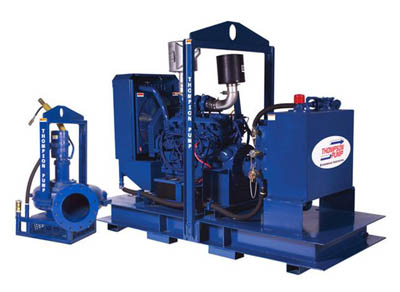
Our submersible hydraulic water pump is more versatile and efficient than traditional electric pumps. These portable hydraulic water pumps utilize a highly efficient design to remove water quickly. Moreover, they can run dry and require no cooling while operating.
RGC offers Flow Dividers, allowing you to run RGC tools from an auxiliary power supply. We also offer additional supplies and accessories for our hydraulic water pumps, including hose whips, hydraulic hoses, and biodegradable hydraulic oil.
Questions about our hydraulic water pumps for sale? Reach out to us online by filling out our contact form, or call us at 800-831-5438. With over 75 years of experience in hydraulic tool manufacturing, we’re happy to help in any way we can. Our expert team will answer any questions and provide you with more information regarding our pump products and hydraulic tools.

The TP30 pump provides 450 gpm of discharge capacity and can pump solids up to 3" in diameter. The TP40 has a 800 gpm of discharge capacity and can pump up to 4" diameter solids.
Hydraulic TP40 compact submersible trash pump is a light weight, efficient way to move large volumes of liquids that can contain sand, dirt and gravel very quickly. This submersible centrifugal...
Hydraulic TP40 compact submersible trash pump is a light weight, efficient way to move large volumes of liquids that can contain sand, dirt and gravel very quickly. This submersible centrifugal design requires no priming and can run dry all day wi...
The TP30 compact submersible trash pump is a light weight, efficient way to move large volumes of liquids that can contain sand, dirt and gravel very quickly. This submersible centrifugal design requires no priming and can run dry all day without ...
Submersible trash pump for dewatering construction sites. The SP20 compact submersible Hydraulic pump is a light weight, efficient way to move large volumes of liquids quickly. See flow chart to see how much hydraulic oil. 5-8gpm

Rietschle KLR Claw Pressure / Vacuum Pumps - Dry Running feature an optimized, high precision shape and roll together without contact, synchronized by a precision gear set. The compression is achieved dry and wear free.
Dry Running is an undesirable condition which affects most pump designs and is characterised when a pump operates without an adequate amount of fluid. In most pump technologies, this leads to cavitation and critical damage to the internal pumping elements such as impellers, lobes, gears, casings, seals & bearings.
Dry running is usually related to how the pump is operated, monitored & controlled which is typically a result of human error. Companies generally rely on their operators to monitor the pumps on the line, however, problems will arise when a pump is unintentionally left running for prolonged periods of time after the intended operation has been completed. For example, during offloading of a tanker, an operator may leave the pump unattended whilst the tanker is being evacuated and the pump may over-run when the tanker is empty thus resulting in damage to the pump internals.
Dry running could lead mechanical seals to wearing quickly which could cause the pump to leak. This will allow the potentially hazardous liquid to spill putting pump operators at risk.
Dry running can damage your pump which could cause an immediate stop to your production line meaning a loss of production – delays & costs to your business
Risked cavitation if dry run for long periods of time which may require the whole pump to be replaced if there has been serious damage to the impellers in your pump
Dry Running can be extremely costly to your business so please check with your supplier or the pump manufacturer whether the pump you’ve purchased can be dry run before operating it.
When using most pump designs, such as Rotodynamic as well as Reciprocating and Rotary Positive Displacement Pumps, most companies need to install protection and control devises on the pumps and system to ensure that the pump is stopped immediately after the pumping operation is complete, or in the absence of fluid at the pump suction or source.
Pressure or Level Switch Protection:Pressure Switches fitted to the suction pipe or port of the pump(s) or Float Switches/Electrode Relays in the Supply tank
Engineers on-site and Operators spend significant amounts of time ensuring pumps are properly installed & primed, significantly increasing the cost and complexity of the installation. However, despite all these efforts, the ever-present possibility of human error, malfunctioning control and monitoring equipment, unpredictable events & improper use of equipment means that Dry Running is never completely eradicated. As a result, plant owners are constantly in search of technology and solutions which can prevent or avoid the costly and damaging effects of Dry Running in order to reduce maintenance costs, increase throughput and alleviate pressures put onto operators to constantly monitor, control and protect their equipment on the line.
There are a variety of standard accessories that can be used to control pumping equipment to protect is from dry running such as pressure and temperature sensors. Additional accessories and expensive sealing systems aren’t always the answer. Not all pumps are created equally, in fact, at Tapflo UK we have a variety of pump solutions that will allow you to dry run your pump without causing damage to it. Need your pump to run dry? Let us know when you call us.
Tapflo offer a range of pump technologies that have the added benefit of being able to dry run, including our Diaphragm Pumps and Peristaltic Pumps which can run dry indefinitely without damaging the pump.
Due to their design and construction, both of these pumping technologies are able to operate under dry conditions without experiencing common wear problems associated with dry running. Not only does this alleviate the pressure put on the operator, but it also simplifies the pumping system and reduces the cost of installation and ownership significantly. Of course, these designs, on their own, do not overcome the energy costs affiliated with overrunning equipment, to improve this, Tapflo offers dry run protection devices such as our Pneumatic Guardian System for Diaphragm Pumps which automatically stops your pump when the pumping process is complete.
In summary, Tapflo UK have a full range of pumping solutions which can either protect equipment from Dry Running or indeed avoid problems associated with Dry Running completely! Let’s discuss your options today.

A gear pump is a type of positive displacement (PD) pump. It moves a fluid by repeatedly enclosing a fixed volume using interlocking cogs or gears, transferring it mechanically using a cyclic pumping action. It delivers a smooth pulse-free flow proportional to the rotational speed of its gears.
Gear pumps use the actions of rotating cogs or gears to transfer fluids. The rotating element develops a liquid seal with the pump casing and creates suction at the pump inlet. Fluid, drawn into the pump, is enclosed within the cavities of its rotating gears and transferred to the discharge. There are two basic designs of gear pump: external and internal(Figure 1).
An external gear pump consists of two identical, interlocking gears supported by separate shafts. Generally, one gear is driven by a motor and this drives the other gear (the idler). In some cases, both shafts may be driven by motors. The shafts are supported by bearings on each side of the casing.
As the gears come out of mesh on the inlet side of the pump, they create an expanded volume. Liquid flows into the cavities and is trapped by the gear teeth as the gears continue to rotate against the pump casing.
No fluid is transferred back through the centre, between the gears, because they are interlocked. Close tolerances between the gears and the casing allow the pump to develop suction at the inlet and prevent fluid from leaking back from the discharge side (although leakage is more likely with low viscosity liquids).
An internal gear pump operates on the same principle but the two interlocking gears are of different sizes with one rotating inside the other. The larger gear (the rotor) is an internal gear i.e. it has the teeth projecting on the inside. Within this is a smaller external gear (the idler –only the rotor is driven) mounted off-centre. This is designed to interlock with the rotor such that the gear teeth engage at one point. A pinion and bushing attached to the pump casing holds the idler in position. A fixed crescent-shaped partition or spacer fills the void created by the off-centre mounting position of the idler and acts as a seal between the inlet and outlet ports.
As the gears come out of mesh on the inlet side of the pump, they create an expanded volume. Liquid flows into the cavities and is trapped by the gear teeth as the gears continue to rotate against the pump casing and partition.
Gear pumps are compact and simple with a limited number of moving parts. They are unable to match the pressure generated by reciprocating pumps or the flow rates of centrifugal pumps but offer higher pressures and throughputs than vane or lobe pumps. Gear pumps are particularly suited for pumping oils and other high viscosity fluids.
Of the two designs, external gear pumps are capable of sustaining higher pressures (up to 3000 psi) and flow rates because of the more rigid shaft support and closer tolerances. Internal gear pumps have better suction capabilities and are suited to high viscosity fluids, although they have a useful operating range from 1cP to over 1,000,000cP. Since output is directly proportional to rotational speed, gear pumps are commonly used for metering and blending operations. Gear pumps can be engineered to handle aggressive liquids. While they are commonly made from cast iron or stainless steel, new alloys and composites allow the pumps to handle corrosive liquids such as sulphuric acid, sodium hypochlorite, ferric chloride and sodium hydroxide.
External gear pumps can also be used in hydraulic power applications, typically in vehicles, lifting machinery and mobile plant equipment. Driving a gear pump in reverse, using oil pumped from elsewhere in a system (normally by a tandem pump in the engine), creates a hydraulic motor. This is particularly useful to provide power in areas where electrical equipment is bulky, costly or inconvenient. Tractors, for example, rely on engine-driven external gear pumps to power their services.
Gear pumps are self-priming and can dry-lift although their priming characteristics improve if the gears are wetted. The gears need to be lubricated by the pumped fluid and should not be run dry for prolonged periods. Some gear pump designs can be run in either direction so the same pump can be used to load and unload a vessel, for example.
The close tolerances between the gears and casing mean that these types of pump are susceptible to wear particularly when used with abrasive fluids or feeds containing entrained solids. However, some designs of gear pumps, particularly internal variants, allow the handling of solids. External gear pumps have four bearings in the pumped medium, and tight tolerances, so are less suited to handling abrasive fluids. Internal gear pumps are more robust having only one bearing (sometimes two) running in the fluid. A gear pump should always have a strainer installed on the suction side to protect it from large, potentially damaging, solids.
Generally, if the pump is expected to handle abrasive solids it is advisable to select a pump with a higher capacity so it can be operated at lower speeds to reduce wear. However, it should be borne in mind that the volumetric efficiency of a gear pump is reduced at lower speeds and flow rates. A gear pump should not be operated too far from its recommended speed.
For high temperature applications, it is important to ensure that the operating temperature range is compatible with the pump specification. Thermal expansion of the casing and gears reduces clearances within a pump and this can also lead to increased wear, and in extreme cases, pump failure.
Despite the best precautions, gear pumps generally succumb to wear of the gears, casing and bearings over time. As clearances increase, there is a gradual reduction in efficiency and increase in flow slip: leakage of the pumped fluid from the discharge back to the suction side. Flow slip is proportional to the cube of the clearance between the cog teeth and casing so, in practice, wear has a small effect until a critical point is reached, from which performance degrades rapidly.
Gear pumps continue to pump against a back pressure and, if subjected to a downstream blockage will continue to pressurise the system until the pump, pipework or other equipment fails. Although most gear pumps are equipped with relief valves for this reason, it is always advisable to fit relief valves elsewhere in the system to protect downstream equipment.
Internal gear pumps, operating at low speed, are generally preferred for shear-sensitive liquids such as foodstuffs, paint and soaps. The higher speeds and lower clearances of external gear designs make them unsuitable for these applications. Internal gear pumps are also preferred when hygiene is important because of their mechanical simplicity and the fact that they are easy to strip down, clean and reassemble.
Gear pumps are commonly used for pumping high viscosity fluids such as oil, paints, resins or foodstuffs. They are preferred in any application where accurate dosing or high pressure output is required. The output of a gear pump is not greatly affected by pressure so they also tend to be preferred in any situation where the supply is irregular.
A gear pump moves a fluid by repeatedly enclosing a fixed volume within interlocking cogs or gears, transferring it mechanically to deliver a smooth pulse-free flow proportional to the rotational speed of its gears. There are two basic types: external and internal. An external gear pump consists of two identical, interlocking gears supported by separate shafts. An internal gear pump has two interlocking gears of different sizes with one rotating inside the other.
Gear pumps are commonly used for pumping high viscosity fluids such as oil, paints, resins or foodstuffs. They are also preferred in applications where accurate dosing or high pressure output is required. External gear pumps are capable of sustaining higher pressures (up to 7500 psi) whereas internal gear pumps have better suction capabilities and are more suited to high viscosity and shear-sensitive fluids.

Ace developed the first hydraulic motor driven pump at the request of John Deere in 1969. Many of the original pumps are still operating today after more than 30 years of service.
Centrifugal pump design provides good resistance to abrasive solutions and extra flow for agitation. The advantages of the hydraulic motor driven pump are mounting versatility, customized performance, and ease of maintenance. All hydraulic driven pumps are equipped with a stainless steel shaft and wear ring for excellent corrosion resistance.MOUNTING VERSATILITY:The location of the pump is not tied to the PTO or engine drive shaft; the pump can be mounted in a variety of locations to suit application requirements.
CUSTOMIZED PERFORMANCE: The performance is dependent on the supply of hydraulic oil to the motor and not necessarily tied to engine speed. A hydraulic driven pump can produce higher pressures than PTO or belt driven pumps. They can also hold constant pressure at varying engine speeds on closed center hydraulic systems.
EASY MAINTENANCE: On a hydraulic driven pump there are no belts to align or break. Separate pump and hydraulic motor shafts simplify repair and replacement. Two main pump bearings support shaft loads. All pumps are equipped with easily replaceable FKM mechanical seals.
The Ace gear type hydraulic motor is more efficient than gerotor type motors, and is less subject to damage by contamination than the gerotor design. A built-in needle valve allows for the bypass of up to 9 GPM excess hydraulic fluid on open center systems. The standard motor has a reverse flow check valve which prevents backward hookup and a coasting check which protects the motor seal from the flywheel effect of the impeller. A restrictor orifice is included with pump models recommended for pressure compensating closed center systems. The Ace Internet Hydraulic Selection Guide is here to help in finding the proper hydraulic pump for your tractor.
The 206 motor requires 7 GPM (26.5 LPM) maximum hydraulic fluid input and fits virtually all tractor hydraulic systems. Recommended for:Pressure Compensating Closed Center Systems
The 206 motor requires 7 GPM (26.5 LPM) maximum hydraulic fluid input and fits virtually all tractor hydraulic systems. Recommended for:Pressure Compensating Closed Center Systems
The 310 motor requires 16 GPM (60.6 LPM) maximum hydraulic fluid input. Recommended for:Large Open Center Systems up to 24 GPM (90.9 LPM) using internal needle valve bypass.
The 206 motor requires 7 GPM (26.5 LPM) maximum hydraulic fluid input and fits virtually all tractor hydraulic systems. Recommended for:Pressure Compensating Closed Center Systems
The 206 motor requires 7 GPM (26.5 LPM) maximum hydraulic fluid input and fits virtually all tractor hydraulic systems. Recommended for:Pressure Compensating Closed Center Systems
The 206 motor requires 7 GPM (26.5 LPM) maximum hydraulic fluid input and fits virtually all tractor hydraulic systems. Recommended for:Pressure Compensating Closed Center Systems
The 206 motor requires 7 GPM (26.5 LPM) maximum hydraulic fluid input and fits virtually all tractor hydraulic systems. Recommended for:Pressure Compensating Closed Center Systems
The Gemini DPK (Dual Pump Kit) was designed to solve these concerns. Pick any two pumps with 204 or 206 motors, and run them from one SCV remote port. Run them at different rates. Shut one pump off while leaving the other pump running. Have your rate controller send PWM signal to one or both of the pumps for precision application.
The 310 motor requires 16 GPM (60.6 LPM) maximum hydraulic fluid input. Recommended for:Large Open Center Systems up to 24 GPM (90.9 LPM) using internal needle valve bypass.
Severe duty silicon carbide seal standard - resists abrasive scratching and transfers heat away from seal faces for improved survival during short run-dry events
The 206 motor requires 7 GPM (26.5 LPM) maximum hydraulic fluid input and fits virtually all tractor hydraulic systems. Recommended for:Pressure Compensating Closed Center Systems
The 206 motor requires 7 GPM (26.5 LPM) maximum hydraulic fluid input and fits virtually all tractor hydraulic systems.Pressure Compensating Closed Center Systems
Severe duty silicon carbide seal standard - resists abrasive scratching and transfers heat away from seal faces for improved survival during short run-dry events
The 206 motor requires 7 GPM (26.5 LPM) maximum hydraulic fluid input and fits virtually all tractor hydraulic systems.Pressure Compensating Closed Center Systems
The 206 motor requires 7 GPM (26.5 LPM) maximum hydraulic fluid input and fits virtually all tractor hydraulic systems.Pressure Compensating Closed Center Systems

Dry running occurs when a pump operates without adequate liquid. This leads to a surge in pressure, flow or overheating that will instigate a pump failure. As a result, the pumping elements seize up on the shaft. This article explains how the problem can be avoided.
Pump cavitation and dry run related failures cost companies millions of dollars annually, including replacement costs for damaged equipment and lost sales due to poor performance. With an improving economy and anticipated fuel production increase, sales of fluid-handling pumps are forecast to rise 5.5% annually to $84 billion in 2018.
When cavitation occurs, vapour bubbles form and expand in the pumping liquid on the suction side of the pump before reaching the higher-pressure discharge side of the pump and violently collapsing near the surface of the pumping element. This triggers shock waves inside the pump which cause significant damage to the pumping element.
If left untreated, cavitation will destroy the pumping element and other components over time, drastically shortening the pump’s life. Cavitation may also cause excessive vibration leading to premature seal-and-bearing failure, in addition to creating an immediate increase power consumption and decrease in flow and pressure output.
Whereas cavitation is a common cause of pump degradation and failure related to the physics involved in the pumping operation, dry running on the other hand is usually related to how pumps are actively operated by end users. Cavitation itself may also be so widespread that it creates a dry run situation inside the pump due to excessive vapour formation. Pumps most often rely on the pumping fluid itself to lubricate the bearing surfaces of the pumping element. If a pump is operated without this fluid, the low to non-existent lubrication at these bearing surfaces will cause excess heat generation, increased wear, and potentially even failure of the pump if the pumping element seizes or breaks. The life of a pump subjected to dry run will be significantly reduced or, in the worst case, brought to an untimely end.
The most immediate cause of dry running is usually human error. Companies rely on operators to monitor pumps, but problems occur in cases where operators unintentionally leave pumps running over a period of time after the pumping operation is complete. For example, after offloading is complete, a transfer truck driver may leave a pump running unattended, unaware that the pump is still running. This continued operation after all pumping fluid has been transferred will create a dry run condition inside the pump, leading to damage from this lack of lubrication. Such a situation may also occur during pump priming, where the pipe system and pump casing have not yet been filled with fluid and the pump runs dry until the priming period is over.
In response, many companies have installed protection and control devices of various designs which stop the pump immediately after the pumping operation is complete, preventing dry running from occurring. Engineers also spend significant time and effort to ensure pumps are properly set up for priming, increasing the cost and complexity of plumbing. This level of protection comes at a significant expense. Despite an operator’s best efforts, harmful events still may occur from malfunctioning monitoring systems, improper use of control equipment, or unpredictable events. Pump owners specifically desire a technology to prevent the damaging results of dry running so they are not dependent on operators as their only line of defense. In addition to protection against dry running, pump specifying engineers and maintenance personnel are always in search of a solution to prevent the ever-present problem of cavitation in the most demanding pump applications, with the hopeful result of reduced maintenance costs and increased throughput.
Parker engineers have developed dual-stage hybrid technology by incorporating a centrifugal pump as a first stage in front of a positive displacement rotary tri-lobe pump as a second stage. This dual-stage hybrid approach boosts the flow through the centrifugal impeller, elevating the pressure of the fluid charge for the second stage tri-lobe rotors. In effect, the centrifugal impeller feeds the rotary lobe stage virtually eliminating cavitation issues common in ordinary positive displacement pumps.
The company’s patent-pending, tri-lobe rotors and wiper blade seals are the key to the pump’s dry run capabilities and dry suction capacity. They are pre-loaded against the internal pump casing walls and produce vacuum to 27 inches of mercury. This allows the pump to self-prime, avoiding any dry priming or vapour lock issues common in ordinary centrifugal pumps.
Oil and gas industry operators have raised their voice to solve their top failure modes: extremely short or non-existent dry run time limits and unacceptable levels of cavitation when pumping extremely light liquids with high vapor pressures. Applications which have required two or three different pumps to fully address can now be served by a single product.

Ace developed the first hydraulic motor driven pump at the request of John Deere in 1969. Many of the original pumps are still operating today after more than 30 years of service.
Centrifugal pump design provides good resistance to abrasive solutions and extra flow for agitation. The advantages of the hydraulic motor driven pump are mounting versatility, customized performance, and ease of maintenance. All hydraulic driven pumps are equipped with a stainless steel shaft and wear ring for excellent corrosion resistance.MOUNTING VERSATILITY:The location of the pump is not tied to the PTO or engine drive shaft; the pump can be mounted in a variety of locations to suit application requirements.
CUSTOMIZED PERFORMANCE: The performance is dependent on the supply of hydraulic oil to the motor and not necessarily tied to engine speed. A hydraulic driven pump can produce higher pressures than PTO or belt driven pumps. They can also hold constant pressure at varying engine speeds on closed center hydraulic systems.
EASY MAINTENANCE: On a hydraulic driven pump there are no belts to align or break. Separate pump and hydraulic motor shafts simplify repair and replacement. Two main pump bearings support shaft loads. All pumps are equipped with easily replaceable FKM mechanical seals.
The Ace gear type hydraulic motor is more efficient than gerotor type motors, and is less subject to damage by contamination than the gerotor design. A built-in needle valve allows for the bypass of up to 9 GPM excess hydraulic fluid on open center systems. The standard motor has a reverse flow check valve which prevents backward hookup and a coasting check which protects the motor seal from the flywheel effect of the impeller. A restrictor orifice is included with pump models recommended for pressure compensating closed center systems. The Ace Internet Hydraulic Selection Guide is here to help in finding the proper hydraulic pump for your tractor.
The 206 motor requires 7 GPM (26.5 LPM) maximum hydraulic fluid input and fits virtually all tractor hydraulic systems. Recommended for:Pressure Compensating Closed Center Systems
The 206 motor requires 7 GPM (26.5 LPM) maximum hydraulic fluid input and fits virtually all tractor hydraulic systems. Recommended for:Pressure Compensating Closed Center Systems
The 310 motor requires 16 GPM (60.6 LPM) maximum hydraulic fluid input. Recommended for:Large Open Center Systems up to 24 GPM (90.9 LPM) using internal needle valve bypass.
The 206 motor requires 7 GPM (26.5 LPM) maximum hydraulic fluid input and fits virtually all tractor hydraulic systems. Recommended for:Pressure Compensating Closed Center Systems
The 206 motor requires 7 GPM (26.5 LPM) maximum hydraulic fluid input and fits virtually all tractor hydraulic systems. Recommended for:Pressure Compensating Closed Center Systems
The 206 motor requires 7 GPM (26.5 LPM) maximum hydraulic fluid input and fits virtually all tractor hydraulic systems. Recommended for:Pressure Compensating Closed Center Systems
The 206 motor requires 7 GPM (26.5 LPM) maximum hydraulic fluid input and fits virtually all tractor hydraulic systems. Recommended for:Pressure Compensating Closed Center Systems
The Gemini DPK (Dual Pump Kit) was designed to solve these concerns. Pick any two pumps with 204 or 206 motors, and run them from one SCV remote port. Run them at different rates. Shut one pump off while leaving the other pump running. Have your rate controller send PWM signal to one or both of the pumps for precision application.
The 310 motor requires 16 GPM (60.6 LPM) maximum hydraulic fluid input. Recommended for:Large Open Center Systems up to 24 GPM (90.9 LPM) using internal needle valve bypass.
Severe duty silicon carbide seal standard - resists abrasive scratching and transfers heat away from seal faces for improved survival during short run-dry events
The 206 motor requires 7 GPM (26.5 LPM) maximum hydraulic fluid input and fits virtually all tractor hydraulic systems. Recommended for:Pressure Compensating Closed Center Systems
The 206 motor requires 7 GPM (26.5 LPM) maximum hydraulic fluid input and fits virtually all tractor hydraulic systems.Pressure Compensating Closed Center Systems
Severe duty silicon carbide seal standard - resists abrasive scratching and transfers heat away from seal faces for improved survival during short run-dry events
The 206 motor requires 7 GPM (26.5 LPM) maximum hydraulic fluid input and fits virtually all tractor hydraulic systems.Pressure Compensating Closed Center Systems
The 206 motor requires 7 GPM (26.5 LPM) maximum hydraulic fluid input and fits virtually all tractor hydraulic systems.Pressure Compensating Closed Center Systems
Dry running occurs when a pump operates without adequate liquid. This leads to a surge in pressure, flow or overheating that will instigate a pump failure. As a result, the pumping elements seize up on the shaft. This article explains how the problem can be avoided.
Pump cavitation and dry run related failures cost companies millions of dollars annually, including replacement costs for damaged equipment and lost sales due to poor performance. With an improving economy and anticipated fuel production increase, sales of fluid-handling pumps are forecast to rise 5.5% annually to $84 billion in 2018.
When cavitation occurs, vapour bubbles form and expand in the pumping liquid on the suction side of the pump before reaching the higher-pressure discharge side of the pump and violently collapsing near the surface of the pumping element. This triggers shock waves inside the pump which cause significant damage to the pumping element.
If left untreated, cavitation will destroy the pumping element and other components over time, drastically shortening the pump’s life. Cavitation may also cause excessive vibration leading to premature seal-and-bearing failure, in addition to creating an immediate increase power consumption and decrease in flow and pressure output.
Whereas cavitation is a common cause of pump degradation and failure related to the physics involved in the pumping operation, dry running on the other hand is usually related to how pumps are actively operated by end users. Cavitation itself may also be so widespread that it creates a dry run situation inside the pump due to excessive vapour formation. Pumps most often rely on the pumping fluid itself to lubricate the bearing surfaces of the pumping element. If a pump is operated without this fluid, the low to non-existent lubrication at these bearing surfaces will cause excess heat generation, increased wear, and potentially even failure of the pump if the pumping element seizes or breaks. The life of a pump subjected to dry run will be significantly reduced or, in the worst case, brought to an untimely end.
The most immediate cause of dry running is usually human error. Companies rely on operators to monitor pumps, but problems occur in cases where operators unintentionally leave pumps running over a period of time after the pumping operation is complete. For example, after offloading is complete, a transfer truck driver may leave a pump running unattended, unaware that the pump is still running. This continued operation after all pumping fluid has been transferred will create a dry run condition inside the pump, leading to damage from this lack of lubrication. Such a situation may also occur during pump priming, where the pipe system and pump casing have not yet been filled with fluid and the pump runs dry until the priming period is over.
In response, many companies have installed protection and control devices of various designs which stop the pump immediately after the pumping operation is complete, preventing dry running from occurring. Engineers also spend significant time and effort to ensure pumps are properly set up for priming, increasing the cost and complexity of plumbing. This level of protection comes at a significant expense. Despite an operator’s best efforts, harmful events still may occur from malfunctioning monitoring systems, improper use of control equipment, or unpredictable events. Pump owners specifically desire a technology to prevent the damaging results of dry running so they are not dependent on operators as their only line of defense. In addition to protection against dry running, pump specifying engineers and maintenance personnel are always in search of a solution to prevent the ever-present problem of cavitation in the most demanding pump applications, with the hopeful result of reduced maintenance costs and increased throughput.
Parker engineers have developed dual-stage hybrid technology by incorporating a centrifugal pump as a first stage in front of a positive displacement rotary tri-lobe pump as a second stage. This dual-stage hybrid approach boosts the flow through the centrifugal impeller, elevating the pressure of the fluid charge for the second stage tri-lobe rotors. In effect, the centrifugal impeller feeds the rotary lobe stage virtually eliminating cavitation issues common in ordinary positive displacement pumps.
The company’s patent-pending, tri-lobe rotors and wiper blade seals are the key to the pump’s dry run capabilities and dry suction capacity. They are pre-loaded against the internal pump casing walls and produce vacuum to 27 inches of mercury. This allows the pump to self-prime, avoiding any dry priming or vapour lock issues common in ordinary centrifugal pumps.
Oil and gas industry operators have raised their voice to solve their top failure modes: extremely short or non-existent dry run time limits and unacceptable levels of cavitation when pumping extremely light liquids with high vapor pressures. Applications which have required two or three different pumps to fully address can now be served by a single product.

Vacuum pumps are critical for use in industrial, laboratory, and research applications. When making your decision, consider the flow rate, compression, elastic ability, pressure capacity, cost, and maintenance. Wet pumps and dry pumps both have particular features unique to their design. Learn more about them and you’ll make the right choice that is perfect for your needs.
Water-based wet pumps use water to seal or lubricate. Oil-based pumps use oil. Dry pumps use PTFE dry polymer seals instead of water or oil. A dry vacuum pump may also have a diaphragm to keep the swept gas away from the mechanism that pumps.
The simple wet pump design features two moving parts: the shaft and impeller. The liquid ring pump was created for dewatering and filtration processes.
There is a higher contamination risk in a wet pump. This is because the sealing or lubrication fluid can contaminate the pumped gas. In addition, liquid waste must be properly disposed of.
If you invest in a wet pump and later decide you want to convert it into a dry pump, it will be challenging. There is a risk of contamination when going from wet to dry. The chamber and the piping must be cleaned very well or better yet, replaced. Otherwise, the gas will be contaminated.
Furthermore, wet pumps require oil changes and this tends to be messy. Another important point to make is that the pump may receive oil into its inlet side when it reaches its vaporization point.
The claw pump design offers a high flow rate with the ability to endure tough industrial settings. Manufacturing plants can increase efficiency by operating multiple claw pumps at different assembly line speeds.
The dry rotary vane pump was designed for continuous running at maximum vacuum and pressure. This rotary vane at High Vac Depot is durable, runs quietly, and requires little maintenance.
The rotary screw pump is typically quieter than oil-sealed wet pumps. It has a variable speed drive for efficiency. The pump adapts well in rigorous environments too. The rotary screw fits large industrial settings where a maximum throughput capacity is required.
Since dry pumps are pneumatic, they tend to operate more efficiently than a hydraulic system that uses liquid. However, it depends on the application. When fast volume processing counts, pneumatic may be the best choice. If you are processing very large loads and there is no room for error, hydraulic pumps (wet pumps) may be more suitable.
Concerning compression, dry pumps can be a better choice in certain situations. For example, you may have a process in which a weighty load needs to be brought safely to the ground. A dry pump uses pneumatics so it will perform better at laying down the load than a hydraulic wet pump. You will sacrifice total accuracy in timing as it may be a bit delayed in its movement though.
Just as little as two decades ago, wet pumps were extremely popular. Advanced technology has pushed dry pumps to the forefront. Today, many industries are choosing to forgo the messy oil changes that are the hallmark of wet pumps. Instead, more companies prefer to use dry pumps to lower maintenance and reduce oil contamination risks.
High Vac Depot has a large selection of wet and dry pumps at different price points. The key to making the right decision is to take an in-depth look at your application process. Our specialists are here to assist you in choosing the right wet or dry vacuum pump to meet your needs. Call us at 1-800-289-6945 or contact us online today!

In a recent 2021 Fluid Power Technology Conference — Virtual Series presentation, MSOE University’s Tom Wanke took an in-depth look at Pump and Motor Troubleshooting, Failure Modes and Analysis. One problem that drives engineers and maintenance technicians crazy is when a hydraulic pump underperforms or runs erratically, but doesn’t completely fail. Sorting out the root cause requires a systemic and meticulous approach to troubleshooting, said Wanke. When a pump is delivering some flow, but less than normal, here are nine possible culprits.
Aeration. Fluid aeration and cavitation (discussed below) are considered system faults, as they can be caused by various factors and conditions not related to the pump. Gas bubbles will form due to separation of dissolved air, oil evaporation or entrained air. Bubbles will be transported with the oil to the delivery side of the pump. Bubbles can be sustained in the system if they are formed early enough to grow in size, or if pressure at the delivery side of the pump is relatively low. This is called aeration.
There are many ways air gets into a system. For instance, if there is a leaking fitting in the intake line, tighten it. If the suction hose is porous or has a pin-hole leak, replace it. Likewise, if the pump shaft seal is worn or damaged, install a new seal.
Cavitation. If gas bubbles in the system, described above, implode at the delivery side of the pump at high pressure, this is called cavitation. It can cause high impact forces and severe erosion damage to the components.
Pump undersized. While it may seem obvious, check that you’ve installed the right pump. Make sure you have the correct size pump and proper displacement.
Wrong volume control. Is it a variable-displacement pump? Be sure that the pump is set to deliver the proper flow, and that the volume control is operating properly. Check the pump controller setting and, if necessary, reset the controller to the required value.
Internal leakage or contamination. If the pump delivers low or erratic flow, in addition to other causes listed here, perhaps the pump’s internal parts are sticking. Dissemble, clean and repair; and make sure no varnish or sludge is in the oil. If you suspect excessive wear, conduct a pump performance test and, if necessary, rebuild or replace the pump.
The goal of a hydraulic pump is to move hydraulic fluid through a hydraulic system, acting much like the beating heart of the system. There are two things that all hydraulic pumps have in common: (1) they provide hydraulic flow to other components (e.g., rams, hydraulic motors, cylinder) within a hydraulic system, and (2) they produce flow which in turn generates pressure when there is a resistance to flow. In addition, most hydraulic pumps are motor-driven and include a pressure relief valve as a type of overpressure protection. The three most common types of hydraulic pumps currently in use are gear, piston, and vane pumps.
In a gear pump, hydraulic fluid is trapped between the body of the pump and the areas between the teeth of the pump’s two meshing gears. The driveshaft is used to power one gear while the other remains idle until it meshes with the driving gear. These pumps are what is known as fixed displacement or positive displacement because each rotation of the shaft displaces the same amount of hydraulic fluid at the same pressure. There are two basic types of gear pumps, external and internal, which will be discussed in a moment.
Gear pumps are compact, making them ideal for applications that involve limited space. They are also simple in design, making them easier to repair and maintain. Note that gear pumps usually exhibit the highest efficiency when running at their maximum speed. In general, external gear pumps can produce higher levels of pressure (up to 3,000 psi) and greater throughput than vane pumps.
External gear pumps are often found in close-coupled designs where the gear pump and the hydraulic motor share the same mounting and the same shaft. In an external gear pump, fluid flow occurs around the outside of a pair of meshed external spur gears. The hydraulic fluid moves between the housing of the pump and the gears to create the alternating suction and discharge needed for fluid flow.
External gear pumps can provide very high pressures (up to 3,000 psi), operate at high speeds (3,000 rpm), and run more quietly than internal gear pumps. When gear pumps are designed to handle even higher pressures and speeds, however, they will be very noisy and there may be special precautions that must be made.
External gear pumps are often used in powerlifting applications, as well as areas where electrical equipment would be either too bulky, inconvenient, or costly. External gear pumps can also be found on some agricultural and construction equipment to power their hydraulic systems.
In an internal gear pump, the meshing action of external and internal gears works with a crescent-shaped sector element to generate fluid flow. The outer gear has teeth pointing inwards and the inner gear has teeth pointing outward. As these gears rotate and come in and out of mesh, they create suction and discharge zones with the sector acting as a barrier between these zones. A gerotor is a special type of internal gear pump that eliminates the need for a sector element by using trochoidal gears to create suction and discharge zones.
Unlike external gear pumps, internal gear pumps are not meant for high-pressure applications; however, they do generate flow with very little pulsation present. They are not as widely used in hydraulics as external gear pumps; however, they are used with lube oils and fuel oils and work well for metering applications.
In a piston pump, reciprocating pistons are used to alternately generate suction and discharge. There are two different ways to categorize piston pumps: whether their piston is axially or radially mounted and whether their displacement is fixed or variable.
Piston pumps can handle higher pressures than gear or vane pumps even with comparable displacements, but they tend to be more expensive in terms of the initial cost. They are also more sensitive to contamination, but following strict hydraulic cleanliness guidelines and filtering any hydraulic fluid added to the system can address most contamination issues.
In an axial piston pump, sometimes called an inline axial pump, the pistons are aligned with the axis of the pump and arranged within a circular cylinder block. On one side of the cylinder block are the inlet and outlet ports, while an angled swashplate lies on the other side. As the cylinder block rotates, the pistons move in and out of the cylinder block, thus creating alternating suction and discharge of hydraulic fluid.
Axial piston pumps are ideal for high-pressure, high-volume applications and can often be found powering mission-critical hydraulic systems such as those of jet aircraft.
In a bent-axis piston pump (which many consider a subtype of the axial piston pump), the pump is made up of two sides that meet at an angle. On one side, the drive shaft turns the cylinder block that contains the pistons which match up to bores on the other side of the pump. As the cylinder block rotates, the distances between the pistons and the valving surface vary, thus achieving the necessary suction and discharge.
In a radial piston pump, the pistons lie perpendicular to the axis of the pump and are arranged radially like spokes on a wheel around an eccentrically placed cam. When the drive shaft rotates, the cam moves and pushes the spring-loaded pistons inward as it passes them. Each of these pistons has its own inlet and outlet ports that lead to a chamber. Within this chamber are valves that control the release and intake of hydraulic fluid.
In a fixed displacement pump, the amount of fluid discharged in each reciprocation is the same volume. However, in a variable displacement pump, a change to the angle of the adjustable swashplate can increase or reduce the volume of fluid discharged. This design allows you to vary system speed without having to change engine speed.
When the input shaft of a vane pump rotates, rigid vanes mounted on an eccentric rotor pick up hydraulic fluid and transport it to the outlet of the pump. The area between the vanes increases on the inlet side as hydraulic fluid is drawn inside the pump and decreases on the outlet side to expel the hydraulic fluid through the output port. Vane pumps can be either fixed or variable displacement, as discussed for piston pumps.
Vane pumps are used in utility vehicles (such as those with aerial ladders or buckets) but are not as common today, having been replaced by gear pumps. This does not mean, however, that they are not still in use. They are not designed to handle high pressures but they can generate a good vacuum and even run dry for short periods of time.
There are other key aspects to choosing the right hydraulic pump that goes beyond deciding what type is best adapted to your application. These pump characteristics include the following:
Selecting a pump can be very challenging, but a good place to start is looking at the type of pump that you need. Vane pumps have been largely replaced by compact, durable gear pumps, with external gear pumps working best for high pressure and operating speeds while internal gear pumps are able to generate flow with very little pulsation. However, vane pumps are still good for creating an effective vacuum and can run even when dry for short periods of time. Piston pumps in general are more powerful but, at the same time, more susceptible to contamination.
Whether the pump is needed for the rugged world of mining, the sterile world of food and beverage processing, or the mission-critical aerospace industry, MAC Hydraulics can assist you with selecting, installing, maintaining, and repairing the right pump to meet the needs of your hydraulic system. In the event of a breakdown, our highly skilled technicians can troubleshoot and repair your pump — no matter who the manufacturer happens to be. We also offer on-site services that include common repairs, preventative maintenance, lubrication, cleaning, pressure testing, and setting.

Pumps may become inefficient or even catastrophically fail simply because the wrong type of hydraulic fluid is used. How do you know if you are using the right kind of fluid for your hydraulic pump? The answer to that question is dependent on several factors, including the type of pump, its maximum operating temperature, its maximum operating pressure, and even the type of material the pump’s seals are made from.
Hydraulic fluid (sometimes referred to as hydraulic oil) can serve multiple purposes in a hydraulic system and its individual components — including pumps. These purposes include the following:
In the majority of cases, the most important factor is the ability of the fluid to transmit energy, but that can be compromised if too much heat is trapped within the pump, internal components are allowed to corrode, or there is not enough lubrication to prevent surface damage of the internal components.
The hydraulic pump is the heart of any hydraulic system, and the wrong choice of fluid can seriously impact the pump’s performance and life expectancy. In fact, the use of a fluid that is poorly matched to the pump can lead to a catastrophic failure that can cause cascading issues throughout the system. Issues that can arise as a result of poor fluid choice include:
When it comes time to select a fluid for your system, it is important to know what properties are important for your particular application. The most important characteristics of a hydraulic fluid include its viscosity, lubrication, thermal properties, flammability, stability, and foaming.
Viscosity is a measure of a fluid’s resistance to flow, with honey being an example of high viscosity, water being an example of medium-level viscosity, and most gases exhibiting very low viscosity. It is closely related to temperature, with hydraulic fluids becoming more viscous as temperatures drop.
If a hydraulic fluid has a viscosity that is too high, the system will not perform efficiently due to the losses involved in overcoming the resistance of the fluid to motion. In addition, damage can occur because components within the system will not be fully lubricated. However, if the viscosity is too low, there can still be lubrication issues and the fluid will not be as effective at transmitting energy.
A good hydraulic fluid will serve as a lubricant within the system, protecting critical surfaces from damage and preventing metal-to-metal contact. In some instances, a hydraulic system or pump may require a hydraulic fluid with additives to maintain its lubricity in the presence of high pressures.
For use in an explosive or highly flammable environment, hydraulic fluid should have a high flashpoint. The flashpoint is the temperature at which the hydraulic fluid gives off enough vapor to ignite in air. However, keep in mind that hydraulic fluids can also easily ignite if they are discharged under a high enough pressure to produce a fine oil mist. Hydraulic fluids should have a non-petroleum makeup or contain large amounts of water if flammability is an issue.
Ideally, a hydraulic fluid should be non-volatile. It should remain both physically and chemically stable even in the presence of extreme pressure fluctuations, a wide operating temperature range, and even long-term storage.
Another potential issue with hydraulic fluids is foaming, which occurs when the hydraulic fluid releases trapped gases. Foaming can result in an increased system temperature as well as a loss of hydraulic fluid as the gases are released.
There are three basic types of


 8613371530291