
running hydraulic pump dry quotation

Did you know you can invalidate the warranty of your final drive motor if you make the mistake of dry starting it after you’ve just installed it? Read on to learn what a dry start it, how it can damage your motor, and how to keep it from happening to you.
Many people mistakenly believe that because hydraulic fluid circulates through the hydraulic system that all you need to do is connect the hoses to the right ports and you’re good to go. Just because the hydraulic fluid circulates doesn’t mean you can attach an empty component and expect it to be ready to run. And frankly, there is no excuse for dry starting the planetary side of a final drive motor because there is no circulation of fluid to fall back on.
That damage can lead to flakes and other tiny bits of metal breaking free and contaminating the hydraulic fluid or oil once it has access to these parts. Then you have
Scratches and abrasions lead to a reduction in performance, which means that a brand new final drive motor ends up with compromised efficiency and power from the start. In short, you’ve damaged the motor immediately after installation, and dry start damage is not covered by warranties.
Before starting a hydraulic motor that is either brand new, repaired, or rebuilt, add clean, new hydraulic fluid to the hydraulic hub and make sure there is fresh gear oil in the planetary hub. That is all you need to do in order to avoid a dry start.
Just a few simple steps can help you avoid damaging your final drive hydraulic motor by dry starting it. Since damage caused by a dry start is not covered by warranty, it is all the more important that you make sure your motor has fluid and gear oil before you start it.
is your partner in providing new or remanufactured final drive hydraulic motors from a single mini-excavator to a fleet of heavy equipment. Call today so we can find the right final drive or hydraulic component for you, or check out our online store to.
In a previous article, we explored why, ideally,a pump should not endure dry running. Let’s now examine if a pump CAN survive dry running under system upset conditions.
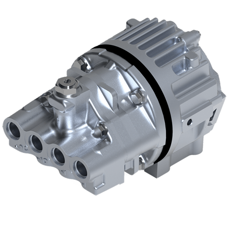
The innovation that has been occurring in pumps has been largely stagnant for a number of years. So the same technology that we saw thirty years ago is really the kind of workhorse technologies that you see in a number of different applications today. With the recent introduction of our innovative high performance, 3-inch positivedisplacement lobe pump, we have taken pump technology to a new level.Supported by deep technical expertise in building pumps for a number of highly technical applications, Parker"s world-class engineering, and manufacturing capability brings a real solution to the challenge of pump failure due to dry running, all in a compact and efficient design.
Built from premium Parker components for unmatched performance and reliability, the newParker 3-inch lobe transfer pump is ideal for a range of applications including:
The utility of this pump is that it will be useful for applications where you might have needed two or three different types of pumps to address the same kind of problem.
It is cavitation resistant and has an impeller to boost the flow. It has two modes of safety. One is a bypass valve on the pump that will automatically engage when the temperature or flow rate gets too high. Additionally, there is a thermal protection circuit on the motor, so when the temperature or flow rates exceed a certain pre-set amount it will shut off power to the motor.
"We can continuously run dry and self-prime, we’re trying to address some of the key failure modes that our customers are seeing (and have shared with us) on a day-to-day basis. We expect that we"ll be able to give them efficiency improvements as well as increase their uptime, which ultimately translates into revenue to the bottom line." Karthik Govindarajan, business development manager

Dry lift pumping applications often require lifting a fluid from below the level of the pump. This is generally not a problem for a positive displacement pump that is primed with fluid. However, getting the pump to self-prime depends not only on the characteristics of the pump, but also on the design of the system and the operating conditions. To understand better the application of a pump required to self-prime, let"s discuss some pump fundamentals and good design practices.
Self-priming with a liquid level below the pump requires lifting the fluid. This means that the pump has to develop enough negative pressure (or vacuum) to pull the fluid up the inlet line into the pump. It is important to note that Micropump® products operate very well under high vacuum fluid conditions. However, when a pump is attempting to prime without fluid inside the pump, it is essentially pumping air. Although Micropump gear pumps are intended for use as fluid pumps, they are able to move air because the internal clearances are relatively small.
The amount of air that a pump is able to move depends on the system design, the type of pump, the amount of internal clearance, how well the internal clearances are sealed, the speed of operation, and the characteristics of the fluid to be pumped.
The first thing to consider in a self-priming application is whether or not it is absolutely necessary to make the pump perform this function. It is always good design practice to avoid making the pump dry lift. A flooded inlet is best. However, if it is necessary for the pump to dry lift, it is recommended that the lift elevation be kept to a minimum.
In some cases a flooded inlet is not enough. Pumping out of a condenser or evacuated reservoir may require additional energy to get the fluid into the pump. It may be necessary to raise the reservoir up 10 meters (30 feet), or more, to provide the necessary inlet pressure needed to fill the pump.
The outlet condition of the pump will also affect the ability of the pump to self-prime. If the pump outlet is blocked or restricted, the air being evacuated from the inlet side has nowhere to go except to leak back through the internal clearances of the pump, and the vacuum created will be considerably reduced.
The type of pump is the next consideration in a self-prime application. Micropump manufactures two types of positive displacement gear pumps: a conventional cavity style and a suction shoe design. In general, the conventional cavity style, such as the Series GJ, is preferred. This series has a fixed cavity with small internal clearances, which make its sealing capabilities very good.
There are three gear materials available in the cavity design: PTFE, Ryton and PEEK. PTFE gears have a relatively high coefficient of thermal expansion compared with stainless steel. This means that if the pump is run dry for an extended period, the gears will heat up and try to expand beyond their internal clearances. This will generally decouple the pump and wear the tips of the gears in the process. This will reduce the volumetric efficiency of the pump, as well as its ability to self-prime.
If PTFE gears are not required, consider Ryton or PEEK gears. These materials have better wear characteristics than PTFE and can be run dry for a longer period of time without damage. Micropump recommends that our pumps never be run dry; however, we have heard claims of pumps with Ryton gears accidentally being run dry for extended periods, and then restarted with fluid, showing no significant loss in performance.
The second type of positive displacement gear pump manufactured by Micropump is the “Suction Shoe” design. In this design, the gears are sealed by a floating “shoe” that is pressure loaded by the differential pressure developed by the pump. In addition, there are two types of suction shoe pumps available: one with graphite components and the other with Ryton or PEEK.
The Series GA pumps use carbon graphite gears (X21, V21, and V23) and suction shoes that are machined to very close tolerances. This low displacement, high precision pump has very small internal clearances and uses a bias spring to physically hold the suction shoe against the gears when self-priming. In this case, these features prevail over the inherent self-priming problems in this design. The design gives the Series GA pumps have very good self-priming characteristics.
In most cases, moisture will improve the sealing of the internal clearances. All Micropump pumps are tested before shipment so they will generally have some fluid left inside. However, if it is possible to wet the gears before starting, the self-priming capability of the pump will significantly improve.
Speed of operation is also important in self-priming. In general, a small displacement pump running at a higher speed will lift better than a larger displacement pump at a lower speed. However, this relationship is not proportional.
There are several types of fluid that are difficult to lift regardless of the pump and system. These include volatile, or low-viscosity fluids, or fluids at high temperature, which can reach their vapor pressure in the inlet line before reaching the pump. Fluids with specific gravities higher than water require higher vacuum to lift the same distance. Also, fluids with high viscosities need more vacuum to overcome viscous drag in the inlet line.
It must be noted that when pumping volatile fluids, such as from a barrel, the fluid path should always be grounded. It is possible for static discharge to occur and cause a spark or fire.
In conclusion, applications requiring a pump to self-prime can be successful if the proper pump design and drive are selected, the properties of the fluid are considered, and good design practices are followed. The pump selection should consider materials and self-priming capability, as well as operating performance. The system should be designed so that lift elevation is minimized and the outlet of the pump is not restricted.
Our submersible hydraulic water pump is more versatile and efficient than traditional electric pumps. These portable hydraulic water pumps utilize a highly efficient design to remove water quickly. Moreover, they can run dry and require no cooling while operating.
RGC offers Flow Dividers, allowing you to run RGC tools from an auxiliary power supply. We also offer additional supplies and accessories for our hydraulic water pumps, including hose whips, hydraulic hoses, and biodegradable hydraulic oil.
Questions about our hydraulic water pumps for sale? Reach out to us online by filling out our contact form, or call us at 800-831-5438. With over 75 years of experience in hydraulic tool manufacturing, we’re happy to help in any way we can. Our expert team will answer any questions and provide you with more information regarding our pump products and hydraulic tools.
Hydraulic pumps are at the core of many essential factory operations. Unfortunately, there are numerous pitfalls to plan for, mitigate, and overcome to keep them running. Keeping up on routine maintenance is important, but the best way factory techs can avail themselves of costly, frustrating breakdowns is to understand the various catalysts for hydraulic pump failure.
The simplest way to identify the cause of pump failure is to thoroughly inspect and dissect the aftermath of the problem. In most cases, the cause of failure will be evident by the nature of the catalyst(s). Here are eight of the most common problems, some of their defining features, and how they ultimately come to fruition.
1. Fluid contamination is one of the biggest causes of hydraulic pump damage and involves debris mixing with the liquid. This debris causes friction, leading to extenuated wear on the pump itself. The result is inefficiency, culminating in malfunction.
2. Fluid viscosity issues occur when the hydraulic fluid within a pump breaks down over time. Viscosity that’s too high leads to cavitation (another catalyst for damage). Subsequently, if a tech changes and replaces fluid with a viscosity that’s too low, heat and friction become concerns.
3. Over-pressurization occurs because of excessive load on the pump itself, resulting in red-line operation that’s both unsafe and damaging. Hydraulic pumps operating under high duress for extended periods of time will likely experience component wear and premature failure, usually in spectacular fashion.
4. Excess heat can be a product of poor fluid viscosity or environmental factors. This issue is rarely a singular catalyst for pump breakdown, but it exacerbates other factors or masks other issues, such as fluid contamination.
5. Implosion invariably results in extreme failure for hydraulic pumps and is a major safety hazard. Implosion occurs when air bubbles within a hydraulic pump collapse, causing an overload of pressure to the pump that generates an intense shock.
6. Aeration occurs when hydraulic fluid traps air bubbles. The pump subjects the bubbles to pressure, causing high heat and over-pressurization when the bubbles collapse. Aeration at extreme levels leads to implosion.
7. Pump aeration pertains to air not in the hydraulic fluid, but air introduced through unsealed joints or shafts. This air quickly causes pressure instability affecting crucial parts of the pump. This can quickly lead to breakdowns — generally marked by a whine or other high-pitched sound.
8. Cavitation is a symptom of uncontrolled pump speeds, which fail to allow hydraulic fluid to completely fill the pump. It results in destabilized pressure, heat, and excess wear. Cavitation is often marked by the same type of whine or squeal as pump aeration.
Because the factors causing each of these problems differ in nature, it’s best to fully evaluate a damaged hydraulic pump to determine if more than one issue is responsible.
Maintenance is the best approach for ensuring safe, efficient hydraulic pump function. But routine service is just the start. Identifying common issues plaguing your hydraulic pumps will lead to a better quality of targeted maintenance — for example, if you pinpoint a heat issue related to viscosity, that issue may be resolved by opting for a different fluid weight.
Every piece of information learned about your pumps can translate into better care, leading to longer uptimes, fewer issues, and fundamentally better maintenance.
Having trouble identifying the catalysts for your hydraulic pump’s issues? Let the professionals at Global Electronic Services take a look! Contact us for all your industrial electronic, servo motor, AC and DC motor, hydraulic, and pneumatic needs — and don’t forget to like and follow us on Facebook!

Hydraulic Trash Pumps are compact submersible pumps designed to efficiently move large volumes of liquids that can contain sand, dirt, and gravel. Trash pumps can handle liquid with up to 30% solids, require no priming, and run dry without damage to the pump.
These urethane pumps have a history of pumping sand, gravel, concrete, and even mortar slurries without issue. The 3” and 4″ trash pumps can also pump petroleum products. The urethane bowl and impeller are extremely durable and lightweight. Hard and sharp materials bounce off instead of abrading the interior surfaces, making this design last longer and perform better than aluminum, iron, and even steel pumps.
Vacuum pumps are critical for use in industrial, laboratory, and research applications. When making your decision, consider the flow rate, compression, elastic ability, pressure capacity, cost, and maintenance. Wet pumps and dry pumps both have particular features unique to their design. Learn more about them and you’ll make the right choice that is perfect for your needs.
Water-based wet pumps use water to seal or lubricate. Oil-based pumps use oil. Dry pumps use PTFE dry polymer seals instead of water or oil. A dry vacuum pump may also have a diaphragm to keep the swept gas away from the mechanism that pumps.
The simple wet pump design features two moving parts: the shaft and impeller. The liquid ring pump was created for dewatering and filtration processes.
There is a higher contamination risk in a wet pump. This is because the sealing or lubrication fluid can contaminate the pumped gas. In addition, liquid waste must be properly disposed of.
If you invest in a wet pump and later decide you want to convert it into a dry pump, it will be challenging. There is a risk of contamination when going from wet to dry. The chamber and the piping must be cleaned very well or better yet, replaced. Otherwise, the gas will be contaminated.
Furthermore, wet pumps require oil changes and this tends to be messy. Another important point to make is that the pump may receive oil into its inlet side when it reaches its vaporization point.
The claw pump design offers a high flow rate with the ability to endure tough industrial settings. Manufacturing plants can increase efficiency by operating multiple claw pumps at different assembly line speeds.
The dry rotary vane pump was designed for continuous running at maximum vacuum and pressure. This rotary vane at High Vac Depot is durable, runs quietly, and requires little maintenance.
The rotary screw pump is typically quieter than oil-sealed wet pumps. It has a variable speed drive for efficiency. The pump adapts well in rigorous environments too. The rotary screw fits large industrial settings where a maximum throughput capacity is required.
Since dry pumps are pneumatic, they tend to operate more efficiently than a hydraulic system that uses liquid. However, it depends on the application. When fast volume processing counts, pneumatic may be the best choice. If you are processing very large loads and there is no room for error, hydraulic pumps (wet pumps) may be more suitable.
Concerning compression, dry pumps can be a better choice in certain situations. For example, you may have a process in which a weighty load needs to be brought safely to the ground. A dry pump uses pneumatics so it will perform better at laying down the load than a hydraulic wet pump. You will sacrifice total accuracy in timing as it may be a bit delayed in its movement though.
Just as little as two decades ago, wet pumps were extremely popular. Advanced technology has pushed dry pumps to the forefront. Today, many industries are choosing to forgo the messy oil changes that are the hallmark of wet pumps. Instead, more companies prefer to use dry pumps to lower maintenance and reduce oil contamination risks.
High Vac Depot has a large selection of wet and dry pumps at different price points. The key to making the right decision is to take an in-depth look at your application process. Our specialists are here to assist you in choosing the right wet or dry vacuum pump to meet your needs. Call us at 1-800-289-6945 or contact us online today!
Wachs Utility Products WDP 3500 is a lightweight, compact, hydraulically powered pump capable of discharging water and solids up to .375in (9.5mm) quickly and quietly. It features cast iron and stainless steel construction for durability, and a direct drive hydraulic motor for continuous use. With no spindle bearings requiring periodic lubrication, it can safely be run dry without damage.
This compact yet rugged hydraulically driven dewatering pump is ideal for tight places. Discharges 500 GPM (1890 LPM) of water at a 40ft (12.2M) head, and is self priming. Requires a hydraulic power source (not included, sold separately) with a 7 to 12 GPM (26.5 to 45 LPM) output. Draws water down to 3.5in (8.9cm)

Dry running a pump can cause all kinds of serious problems, yet many operators are unaware of the dangers. When a pump runs dry, it generates heat and force it was never designed to handle, leading to wear and tear that can quickly add up to inflated repair costs. Avoiding dry running is highly important, but it makes sense to learn how negative it can be in order to fully understand the severity of the phenomenon.
When a pump runs dry, it runs without any liquid going through it. This is always a bad idea, as it puts an inordinate amount of strain on the pump’s moving parts.
Instead of circulating fluid, a dry running pump pushes nothing but air around, leading to friction, heat, and destruction of delicate internals. A hydraulic pump is normally designed to run while filled with fluid. As it runs, the fluid inside it helps to preserve its internal pieces, cooling them and even assisting in centreing moving elements such as the rotor.
Pumps that operate at particularly high pressure can suffer considerable cavitation simply from fluid-derived vapor; completely dry running a finely tuned pump is significantly worse for its longevity. Even self-priming pumps should only be run once the proper amount of fluid is inside, as they can withstand only partial dry conditions while priming themselves.
Running your hydraulic pump dry is likely to result in disaster, wearing it out prematurely via the aforementioned heat, violent vibrations, or complete lock-up/seizure of important parts, costing you money to fix or replace.
Running a hydraulic pump dry can lead to a large variety of issues with the pump’s parts and the rest of your hydraulic system as well. Here are a few common problems that dry running can cause:
High temperatures caused by dry running can ruin your pump, pitting its housing and causing leaks.¹ If heat and pressure are excessive enough, the housing boss may deform, potentially stopping your impeller from rotating freely and rendering your pump functionally useless. In many cases, a severely damaged, leaking pump is likely to need replacing, which can run your costs up much further than anticipated.
As is the case for the housing of your pump, the impeller is susceptible to damage done by excessive heat during use. Dry running your pump causes friction, and this friction is strong enough to heat up the impeller, causing it to melt.² Even minor melting is severely detrimental to your pump’s performance, potentially causing it to seize up and stop working at all. Taking it apart for repair is usually an involved and costly exercise best avoided through preventive operating practices.
Internal wear caused by dry running your pump can lead to additional wear throughout the entirety of your system. This is generally caused by either excessive heat or metal particles scraped from disintegrating moving pieces within your pump travelling through the rest of your system. Metal particles, in particular, can cut and clog valve components, pipes, and tubes, leading to system failure over time.
You may need to run your pump dry for short periods of time to empty the system completely, but it is best to keep such instances as brief as possible. Once your tank or system has been emptied by the pump, it should be turned off. Do not allow it to keep running for more than a minute without any fluid.
Keeping someone in charge of monitoring your pump as it runs can help avoid unintended dry running problems. Often, a pump may be left running until a job is completed. If the pump performs its function faster than intended and all fluid is purged from the system, it will run dry and damage itself until an operator returns to turn it off. Having someone manage the pump at all times is crucial to keeping it functional.
Some companies have found an automatic means of controlling their pumps’ functions from afar. By leveraging special protective devices and control systems, it is possible to automatically stop a pump that is in danger of running dry, preserving its internal parts and averting expensive disasters.³ However, such devices incur an additional cost.
At White House Products, Ltd., we offer all manner ofpump parts to patch up a system damaged by dry running. We can also provide complete replacements as needed. Call our technical support team at +44 (0)1475 742500 to learn how we can help get your pump working again.

Liberty Lift is your hydraulic lift partner with an innovative solution for oilfield production. Our hydraulic jet pumps for oil wells have many advantages, starting with its cutting edge and simple design. The surface pump, manufactured by industry-recognized Wanner Engineering, is the most expensive part of the unit, but unlike costly downhole ESP pumps, it is placed above ground and easily accessible for any needed repairs with minimal downtime and no need for a workover. The sealless pump design has no packing or stuffing box which can leak or fail prematurely as is often the case with conventional plunger type pumps. The pump can run dry indefinitely even with a blocked suction line. The power fluid is generally condensate, water or hydrocarbon liquids available at the weIl site. Chemicals or diluents can also be combined with the power fluid to address downhole flow and tubular corrosion problems.
The bottom hole assembly of the Liberty Lift system centers around the Select-Jet pump placed in the well. The pump handles high fluid volumes with heavy solids and gas. There are no moving parts in this downhole assembly. Depending on the best solution for unloading the well, the pump incorporates a standard flow option with power fluid injected down the tubing, while taking returns up the casing. Alternatively, the reverse flow jet system allows pumping down the casing annulus with returns up the tubing string. Its flexibility allows it to have slim hole capability with integral joints as small as 1” within a 2 ¼” tubing and 7” casing, offering the highest flow volumes in the industry.
The jet pump system, for sale or rent by Liberty Lift, operates efficiently in multiple applications – shallow or deep wells with vertical, horizontal or multiple deviations. It has low operating costs, no VOC emissions, reduced maintenance and the ability to wireline or hydraulically retrieve downhole parts without workover intervention. It is a reliable and productive choice for wells with wide ranging depths and production capabilities.
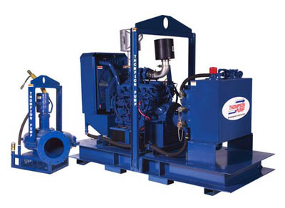
Hydraulic jet pumps are a proven means of artificial lift that have been used for generations in the production of oil and gas. Normally they are utilized for high volume initial production and well unloading with high rates as an alternative to gas lift systems or electric submersible pumps (ESPs). They are also a favorable choice where high flow rates are required in wells having a heavy concentration of sand or other solids from frac operations and can handle high gas volumes. The pumping units are normally skid mounted in a compact above-ground package that includes the hydraulically balanced diaphragm pump that provides power fluid to 5,000 psi pumped down the tubing for returns up the casing or a reverse method of pumping down the casing with tubing returns. The skid includes instrumentation that monitors high and low pressure for both the pumps suction and discharge. In addition, there are meters for flow, high and low oil pressure reading, vibration sensing and pulsation dampening.
Hydraulic jet pump systems have several advantages over the alternative artificial lift methods at this early point in the well’s life cycle. Without an infrastructure that includes wellhead gas availability, the gas lift method is not generally feasible. While ESPs can initially be less expensive as a capital cost item, their reliability in rugged service has been questionable and costly. The major part of their cost is the downhole portion of the unit, positioned at the bottom of the tubing string. When they fail prematurely with mechanical problems, often due to plugging with sand or sediment, they require a workover rig for service and replacement. This operation necessitates pulling the tubing string entirely from the well.


 8613371530291