
sae hydraulic pump mount dimensions brands
For many years the only standardization on pump and motor shafts and mounting flanges had been the SAE (Society of Automotive Engineers) Standard J744a. It was widely accepted by other industries as well as the automotive and is still a valid standard. The NFPA (National Fluid Power Association) started work in 1962 on a set of standards which would more directly apply to industrial fluid power pumps and motors, and would be more complete. This set of standards was unanimously approved by the NFPA Board of Directors and issued in 1965 as NFPA Recommended Standard T3.9.65.1. In 1966 it was also adopted by the ANSI (American National Standards Institute) and issued as B93.6-1966. It has since been revised and now carries the numbers ANSI B93.6-1972 and NFPA T3.9.2 R1. Copies are available from the NFPA.
The purpose of the standard is to encourage manufacturers to use interchangeable dimensions on both mounting flanges and shafts as far as possible to simplify dimensional interchangeability. No standards presently exist for foot mounting dimensions. No performance specifications exist although recommended methods of testing pumps and motors and the manner of presenting test data are given in NFPA Recommended Standard T3.9.17-1971.
The new NFPA and ANSI standards are similar to the SAE standards but differ in these respects: Additional shaft diameters and an alternative long length shaft have been added to the straight-shaft-without-thread listings. Additional mounting flange sizes have been added to provide a wider selection for the designer. NFPA has not assigned any horsepower ratings, making it the responsibility of the pump designer. However, the SAE horsepower ratings are shown for mounting flanges.

It is not uncommon that we will need to couple pumps, motors and/or engines together. Jaw-style couplers help with joining shafts together. With the use of these couplers, we can adapt and fit many different types of shafts together, but interestingly, there are so few choices! Granted, there are lots of choices in the catalogue, but it seems that there should be many more shaft sizes, spline cuts and keys to choose from. Why aren’t there more? Also, what about the outside of the parts? They look like they were designed to be mated with something.
Your questions are not unfounded. There was a standardization that took place years ago. SAE led the way with standardized shafts and mounting flanges in SAE J744. The standard takes a seemingly infinite number of combinations and boils it down to a manageable number of combinations. The fewer the choices, the easier it is on engineers. Plus, manufacturers can often bring a product to market quicker since there aren’t many custom options.
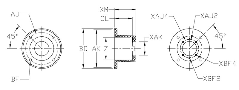
The Society of Automotive Engineers (SAE) has standardized the mounting flanges for hydraulic pumps and motors using a letter codes and the number of bolts used. The sizes are already designed to be able to properly carry the load with medium strength fastener (Grade 5 or equivalent)
SAE J744 specifies the flanges by a letter and a bolt count. In a two bolt pattern, the two bolts and center pilot are all in line. Two bolt flanges (black) come in AA, A, B, C, D and E configurations. Each one gets successively larger. The four-bolt ones have the center pilot surrounded by four bolts arranged in a square around it. These four-bolt (blue) configurations are available in B, C, D and E configurations. These flanges are constructed so that the center pilot will take the main x-y loads and the bolts only take the torque load. Below, is a table for the two bolt configurations. It contains the pitch circle diameter, PCD, which is the diameter of a circle drawn centered at the pilot and intersects the center of the bolt holes. It also has the size of the bolt holes and the pilot diameter.
Keeping your pump and motors on the same center and parallel is critical and often difficult to do. It can mean the difference between a long-lasting system and one that constantly needs maintenance. The example here, a log splitter, is almost exactly how notto do this. Let’s take a look at several problems:
This is not ideal and will definitely wear out the spider coupler faster. However, there are three options to get great alignment with a pump or motor.
Many times you can buy a pre-machined cast aluminum coupler if you are coupling an electric motor or gas engine to a hydraulic pump. Grainger, McMaster Carr and many others have these products online. They are wonderful because they ensure that the shafts will lineup perfectly and have an added safety feature. They usually shield all the way around except for a small opening so that you can tighten set screws in the jaw coupler. Some even have options for a plastic or rubber plug to fill this hole. I always opt for this option. Be sure to mount with the opening on top so that the plug does not fill with water and debris or the vibrations cause it to fall out.
SAE has standardized shaft configurations to use keyways and splines to attach components. This limits the number of choices for each shaft size to one key and one spline. This makes it easy for the customer to specify mating components and the manufacturer to minimize component configurations.
You may have noticed that I skipped over close coupled arrangements. I did that because I wanted to discuss SAE shafts first. We will address that later in this section.
A splined shaft is much different. The full description is SAE 30° involute spline shaft, but in practice if you say splined shaft everyone will know what you are talking about. In appearance, they look like gears and essentially that is what they are. As you can guess, they do not have any mechanism to deal with over torque like a keyed shaft does. So these also have the same SAE letter codes available as a keyed shaft. A sizing table will have the spline details, nominal diameter and total length. Spline detail are displayed as 11T 16/32 DP. This is similar to how a gear is specified. In this example, the spline has 11 teeth and 16 teeth per inch of diameter (DP, diametric pitch). I’ll be honest; I do not know why the 32 is there. It seems redundant to me. The bottom line is this; if the teeth and diametric pitch match, the shaft and hub will fit together.
Yes, finally to the close coupling. This is when we fit our pump or motor to have either a splined or keyed hub instead of a shaft. This allows us to eliminate the entire issue of shaft alignment and jaw couplers by inserting the electric motor shaft inside the pump. In the image here, you can see that the pump is directly connected to the motor and there is no housing or coupler. This is a great option if you are driving multiple pumps from the same power source. In this case, you can have the pump that attaches to the motor with a hub on one side and a shaft on the other. You can then attach your second pump. Granted, having a hub instead of a shaft is more expensive on the front end, but it may end up paying for itself quickly if you can eliminate jaw couplers, machined framework and the time it takes to assemble.
In figuring out the specifications of our parts, SAE has helped by laying out the information for us. A very quick web search will provide you with the tables of all the shaft and mounting information. All that needs to be done is to answer these questions:
One last word of advice when working with couplers and shafts: Remember to always use anti-seize between the two faces in order to prevent any rust or corrosion. It is more than likely that you will need to remove or separate these parts at some point. If these components rust together, you might as well throw them away. You can try to pry them apart or use heat, but it is more than likely you will damage the internal components of your pump and motor in the process. Please, use the anti-seize. It is inexpensive and available in any auto parts store.

This SAE Standard applies to hydraulic pumps and motors used on off-road self-propelled work machines as described in categories 1 through 5 of SAE J1116 JUN86.

The pump mounting flanges are made of steel and cast iron for hydraulic pumps with flange connections according to SAE-A, -B, -C, -D and-E in a design with 2 holes and 4 holes.
Pump connection housings made of cast iron of our portfolio are suitable for direct mounting to the back plate of the engine. Our pump mounting flanges are also availabe with surface coating as well as special flange dimensions on request.

At OneHydraulics, we aim for 100% customer satisfaction on every order. If you are not completely satisfied with your order, please contact us right away so we can make it right.
Items purchased on onehydraulics.comwith inventory from our Houstonlocation can be returned within 30 days from the date it was shipped. Items purchased that come from our manufacturer"s stock may be subject to restocking fees as determined by our manufacturers. Before returning any products, please verify with OneHydraulics if a restock fee is required for the product return.
Any item custom manufactured for a customer’s application,including winches and other made-to-order products, may be non-cancellable and non-returnable. OneHydraulics will not accept returns on those items for any reason. If you may need to return a product you are ordering, please verify if it may be returned prior to ordering.
All items must be returned in NEW condition, in the original packaging. We will not accept items that have been used or purchased from another company. All returns are subject to a restocking fee and shipping fees are non-refundable. If a return is required as a result of an error made by OneHydraulics (e.g., shipping an incorrect item, etc.), the abovementioned fees may not apply. Please contact your sales person or emailsales@onehydraulics.comso we can fix any errors relating to your order immediately.
Please see our Terms and Conditions relating to warranty claims. Prior to shipping an item back to OneHydraulics, you must first obtain a Return Goods Authorization (RGA) form and number. All returns must be shipped prepaid, with the RGA number clearly marked on the outside of the shipping carton. All items must be packaged properly to prevent damage upon shipping back to OneHydraulics. Failure to do so may result in a rejection of the return. Following our inspection, you will be notified of the product’s disposition and charges, if any. Products returned for factory warranty issues must be accompanied by a report explaining the non-performance or failure of the returned part. Please contact OneHydraulics prior to shipping back any item relating to a warranty issue, as those items may need to ship back to the factory directly.
Any item labeled ‘Final Sale’ on the website is non-cancellable and non-returnable. Any item custom manufactured for a customer’s application is non-cancellable and non-returnable. OneHydraulics will not accept returns on those items for any reason.


 8613371530291