
servo driven hydraulic pump free sample
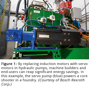
In a conventional hydraulic system, a fixed-speed motor drives the pump that circulates the hydraulic oil from the reservoir to the hydraulic cylinder. To keep the oil circulating, the pump needs to run constantly, consuming energy even when the actuator is stationary.
Pumps in hydraulic systems are commonly driven by induction motors, which are inherently less efficient than the permanent-magnet motors used in servo designs. Induction motors have to draw current in order to generate the magnetic field required to get the rotor to turn. Their efficiency also decreases when they are run below their rated speed.
Of course, if you’re reading this article, you probably know about these problems firsthand. What you need is a solution. Hybrid electrohydraulic systems leverage the power density of hydraulics with the responsiveness and energy savings of electromechanical technology. Unlike the induction motors used in fixed-speed pumps, the permanent magnet motors used in servo pumps operate synchronously and without any latency. Even better, they run efficiently across a range of speeds. “With a servo pump, you don’t have to have continuously circulating hydraulic fluid,” says Kerns. “Basically, the motor comes on and runs when you need pressure, and with a much faster response time.”
This means that you’re not paying to operate the pump full speed when the hydraulic actuator is stationary. Indeed, analysis shows that a conventional hydraulic system will cost considerably more over time than a hybrid version using a servo pump (see figure 2).
“The end-user gets energy savings very similar to that of an all-electric driven machine,” says Monte Swinford, regional factory automation sales manager for Bosch-Rexroth (Hoffman Estates, Illinois). “If they run the same part, same cycle, they will see significant savings. I had one client who saw a 90% reduction in energy usage.”
The instant response delivered by servo motors enables the actuator to operate much more quickly and deterministically, making it a good fit for applications like punch presses. The solutions also involve less complex systems with smaller footprints while incorporating value-added devices like smart drives with real-time diagnostic capabilities (see figure 3). In the case of applications that would normally place the reservoir at a distance from the hydraulic cylinder, the use of a servo pump at the actuator can eliminate the need for long hydraulic hoses that are prone to leaks or breakage.
Applications like injection molding are perfectly positioned to benefit from the technology. Rubber injection molding processes, for example, require the pressure to be applied and then maintained at a set level for an extended period of time while the rubber fills all nooks and crannies of the mold. In the case of a system run by a fixed-speed pump, the motor would be running the entire time, consuming power and generating heat, even though it is only maintaining pressure. With a servo pump, the holding torque of the motor is sufficient to generate the required pressure. “Because you’re using permanent-magnet servo motors, there’s virtually no voltage on the motor,” says Raymond Seifert, director of application engineering, Baumueller Nuermont Corp. (Windsor, CT). ”As a result, even though you might have to maintain a holding current, the actual power that you’re using is minimal.”
Indeed, a calculation of energy consumption and cost for this application based on the duty cycle of the motor showed a clear advantage for the servo-driven design. “The customer was happy with the prototype and could justify the cost,” Seifert says. “They are now looking at retrofitting more machines.”
A new hybrid electrohydraulic press using a dual-pump design has been developed as an off-shoot of the servo-motor-driven pump technology. The approach allows bi-directional pumping of the hydraulic fluid, enabling the customer to reduce the size of the existing hydraulic press reservoir to nothing more than an accumulator in the hydraulic circuit. Fewer components and less oil means a smaller footprint, lower cost for the system, better products, less chance of leakage, and less money spent on both purchase and disposal of the hydraulic oil.
Of course, shrinking the volume of oil does increase the importance of thermal management. The smaller volume of oil means that it heats up more quickly. When the temperatures get too high, the pump can fail. To guard against this, the addition of auxiliary cooling in the hydraulic circuit may be necessary to ensure temperatures remain under control.
Servo pumps deliver benefits beyond just cost savings. The level of control provided by closed-loop feedback leads to more precise motion. In contrast, conventional hydraulic systems may not even use a drive, let alone feedback. They may simply use a motor with a simple on/off switch that runs at constant speed. The closed loop feedback of a servo pump equips the system to deliver the exact torque or speed required for the application, and do it instantly.
“Even if you use a drive with a standard induction motor, you still have an element of delay in getting that system up to a certain pressure,” says Kerns. “More often than not, you’ll see a hydraulic system that doesn’t even have a digital feedback loop, just a regular analog loop. The big benefits of the servo motor are the response time and the fact that you’re able to run those motors up to really, really high RPMs to get to where you need to be much quicker.”
This level of fine control can benefit applications like metalforming. When metal is deformed into a shape, it has to be slightly over bent so that it will assume the correct form after recoil. For best results, full force should only be applied in the last millimeter or two of motion. Servo pumps enable much more accurate control of the motion of the hydraulic actuator, creating better quality parts.
Although system cost and performance are important, the modern industrial environment imposes other challenges to machine design and operation. Particularly if you are involved in industries like automotive manufacturing, you face growing regulation for working conditions. Here, too, servo motors provide superior solution to conventional fixed-speed pump designs by virtue of their whisper-quiet performance. “When customers take the risk and make the change, their jaws just drop with how quiet their new machine is,” says Swinford. That performance is not just good for end-users but for OEMs, he notes. “I have one client who has kept their factory full for the last three years because their end users are so excited by the noise reduction that they keep ordering new machines just to replace the ones in the field. Most of them wind up having flashing lights on the machine to let customers know that the power’s on.”
As intriguing as the technology may be, it’s important to remember that the performance of the system is only as good as the design approach. “It’s not the kind of thing that you just kind of slap together,” Swinford says, citing limiting factors like minimum and maximum pump speed, pressure rises, etc. “The best thing to do is to start with a clean piece of paper. Sure, you can just add something onto what you have and make it work, but it’s not going to be as competitive in the global marketplaces as starting over.”
Everyone interviewed for this article agreed that the adoption of the technology is still in the early stages. Far from tempting manufacturers to wait until later to consider the technology, that should spur OEMs and end-users alike to explore the use of servo pumps. Taking action at the beginning of a market evolution is the way to derive maximum benefit from the conversion. Designing servo pumps into your next hydraulic system will position your organization to gain a significant competitive advantage over organizations working with the incumbent technology.

Constant pumps are generally used in servo-hydraulic systems. Baumüller can work with any of the standard pump manufacturers on request. Numerous manufacturers have their own series for variable-speed operation in their product range that exactly meets the requirements of servo-hydraulic systems and is designed for high accelerations. Compared to an uncontrolled hydraulic system with a standard motor, the pump will be smaller because decoupling from the mains is a frequent occurrence. This allows a higher speed and smaller pump dimensions.
As a special feature, Baumüller offers three different options for the connection between the pump and motor. In the Standard Line, the attachment is made using the conventional solution of coupling and pump support. This tried-and-tested option can be achieved with a standard motor shaft and motor flange and is flexible due to the separate components. The second development stage, the Advanced Line, describes the direct attachment of the pump on the motor via internal toothing. Here there is no need for a pump support and coupling, so the system is more compact and robust. Omitting the pump support as a resonating body also reduces the noise impact. In the third stage, the Performance Line, the hydraulic fluid is additionally used for intelligent circulating oil lubrication. For this purpose, connections were added not only to the motor but also to the constant pump, allowing the leakage flow of the pump to be used for the permanent lubrication of the toothing. This eliminates an otherwise necessary grease lubrication of the internal toothing, which would be due every 3,000 operating hours on average, also rendering the system particularly robust. Baumüller thus offers a solution registered for patent, which leads to significantly reduced service costs in operation.

Baumüller supplies innovative and optimized drive solutions for all sectors through years of intensive cooperation with mechanical engineers. Due to the integrated control unit in the converter, Baumüller servo pumps can easily be connected to your machine control systems. In the process, they reduce the energy consumption of your drive system significantly and also allow for shorter cycle times, greater accuracy as well as lower noise development. See for yourself and rely on the flexibility and power of innovation of the experts from Baumüller.
Servo pump drives for the hydraulic supply consist of a fixed displacement pump driven by a servo motor. The flow rate and pressure can be controlled precisely by highly dynamic changing of the motor speed. If neither flow rate nor pressure are required, the motor stops and does not consume any energy.
These production steps are highly differentiated, meaning that within one process step the injection molding machine has widely fluctuating output requirements. Closing and injection sequences require large quantities of hydraulic oil and a high volumetric flow. Cooling times, on the other hand, require no or just minimal output.
The difference in energy consumption can be clearly seen in the typical hydraulic system shown in the diagram. The high energy efficiency of the servo-hydraulic solution arises from a needs-specific pump output. When the machine is at rest, e.g. during cooling, then the motors will also be at rest and will consume no energy.
An additional example is presses. The cycle in the figure is divided into three partial cycles: lose press (compacting the material), dwell time, press back and handling. The comparison of energy consumption between the three different systems shows that the solution with a servo pump in the individual partial cycles has a significantly lower power input and thus has a significantly lower energy consumption overall. Unlike conventional hydraulic systems, only the energy that is actually needed is used, while in the classic systems the losses are higher due to the constant revolution of the standard motor in rest phases, such as when stopped (see figure).
Injection molding machines and presses are not the only applications for servo-motor pumps. The use of a servo-hydraulic system is a sensible option wherever phases with high power requirements alternate with pause times in the machine cycle, such as in stamping and bending machines.
The advantages of hydraulic power transfer and electric power setting using servo technology combined, as an alternative to hydraulic pressure and volumetric flow control, yields an energy-efficient and cost-effective solution in the form of a dynamically controllable servo pump.
As a special feature, Baumüller offers three different options for the connection between the pump and the motor. In the Standard Line, the attachment is made using the conventional solution of coupling and pump support. This tried-and-tested option can be achieved with a standard motor shaft and motor flange and is flexible due to the separate components. The second development stage, the Advanced Line, designates the direct attachment of the pump on the motor via internal toothing. Here, there is no need for a pump support and coupling, so the system is more compact and robust. Omitting the pump support as a resonating body also reduces the noise impact.
In the third stage, the Performance Line, the hydraulic fluid is additionally used for intelligent circulating oil lubrication. For this purpose, connections were added not only to the motor but also to the fixed displacement pump, allowing the leakage flow of the pump to be used for the permanent lubrication of the toothing. This eliminates an otherwise necessary grease lubrication of the internal toothing, which would be due every 3,000 operating hours on average, also rendering the system particularly robust. Baumüller thus offers a patent-pending solution, which leads to significantly reduced service costs in operation.
Permanent magnet synchronous motors are used as motors in servo-hydraulic systems. The main criterion for selecting servo motors is good performance in terms of dynamics and overload capacity.
Baumüller offers various motor series for use in servo-hydraulic systems, from the dynamic three-phase current servo motor DSD2 to the three-phase current synchronous motor DS2. All motors are available in an air-cooled and a water-cooled version. Size 45–132 servo motors are also available in an oil-cooled form. This is an advantage in the hydraulic system, since the oil is available in the machine anyway. Another advantage is that liquid-cooled motors have a higher power density and can therefore be dimensioned smaller.
Direct attachment is available for the Advanced and Performance Line models. The following motor-pump combinations are possible. The Standard line, attachment via coupling and pump support is possible with all the motors listed here.
We first list the advantages of both pneumatic and hydraulic drive systems. Then we explain why these systems are increasingly being replaced – for example in the automotive industry – for a servo motor gearbox combination. Apex Dynamics’ extensive experience with this transition means that we can provide our customers with excellent information about the possibilities.
Many processes in the industry still make extensive use of hydraulics and pneumatics. Hydraulics uses a fluid under pressure, while pneumatics uses compressed gases such as air. Both types can be used for rotary (motors, pumps) and linear (cylinder) applications.
Such a servo motor gearbox combination also requires little or no maintenance, the control, motor and gearbox are maintenance-free. There is no chance of leaking hoses or pipes and the settings are and will always remain the same. The annoying hiss of pneumatics or the hum of hydraulics is also eliminated. In addition, a servo system can perfectly fit into a mobile solution, due to its compact design and high efficiency.
We see the best examples of this in the automotive industry. The pneumatic and hydraulic drive systems of modern cars (for example the power steering, power brakes, hand-brake and clutch) have been replaced by small servo motors. This saves a lot of mechanics, and thus wear-prone hoses, toothed belts, V-belts and tensioning devices under the hood!
At Apex Dynamics we have already converted a wide variety of projects over the years from a pneumatic or hydraulic drive system to a servo-mechanical solution. Some examples: shears and press brakes, punching lines, cutting machines, bending machines. Are you considering this step for your application or are you curious about the benefits?

The rotor of a DC servo motor is made up of a brush and a shaft. The outer housing is attached to a commutator and a metal support frame that fits the rotor, and the armature winding is wound on the rotor"s metal support frame.
Another feature of this servo motor is that the direction of the torque produced by the motor is determined by the instantaneous polarity of the control voltage. DC servo motors are classified as series motors, control shunt motors, series shunt motors, and permanent magnet shunt motors.
A DC reference voltage is set to the value corresponding to the desired output in the RC servo motor type. Depending on the control circuit, this voltage can be applied to the voltage converter via a potentiometer, a control pulse width (PWM) generator, or timers. Adjusting the potentiometer generates a corresponding voltage, which is then applied to the error amplifier"s input. In digital control, a microprocessor or microcontroller generates the PWM pulses to produce more accurate control signals.
The series servo motors have a high starting torque and draw a large current. This motor has very little speed regulation. Turnaround can be accomplished by flipping the field voltage polarity with a split series field winding.
The squirrel cage induction motor is powered by a motor composed of shortened wire loops on a rotating armature. The voltage in the rotor is "induced" by electromagnetic induction. The main distinction between an induction servo motor and a standard induction motor is that the servo"s cage rotor is made of thinner conductor bars, resulting in lower motor resistance.
They are strong, versatile, and capable of delivering significant power. However, they are more commonly found in larger applications due to poor performance at low powers. The synchronous AC servo motor, consisting of a stator and a rotor, is the industry"s most common type of servo motor. The stator consists of a cylindrical structure and a core, and the induction coil is wound around the stator core with one end connected to a conductor wire that supplies current to the motor.
Initially, there is a position difference between the generator shaft and the control transformer shaft, which we refer to as an error. The voltage across the control transformer reflects this error, which is amplified before reaching the servo motor phase control. Using the control voltage, the servomotor rotor rotates in the direction required for the error to become zero. This is the fundamental principle that ensures AC servomotor axis position.
PLCs and microprocessors are used in most modern servo drives to generate variable frequency and voltage to drive the motor. This control employs PWM and PID control techniques. A block diagram of an AC servo motor system with programmable logic controllers, position controllers, and servo controllers is shown below:
Positional Rotation Servos feature a 180-degree variation in reference to the zero of its axis and constructive mechanisms (stop gears) that allow it to stop with movement precision.
As its name implies, a continuous rotation servo has no restrictions on the rotation"s spatial range. The servo input, in this case, is directly linked to the output speed and direction, allowing the motor to rotate without limits of movement and in both clockwise and counterclockwise directions.
Furthermore, a rack and pinion mechanism allows the linear-type servo to control shaft rotation, translating rotational space variation into linear motion.
Using a quadratic signal oscillation, the control technique known as pulse width modulation (PWM) tries to produce a variable signal. A better resolution signal message is determined by the widths of each pulse or the amount of time each pulse spends at each logic level (low and high). The servo motor"s rotational direction and rate are then determined by this signal.
Analog servos have PWM power signals while transmitting actions to the servo, causing the reaction time to be delayed when producing torque from inertia.
The servo motor is small and efficient, but it has a serious application in some applications, such as precise position control. A pulse width modulator signal drives this motor. Servo motors are used primarily in computers, robotics, toys, CD/DVD players, and other electronic devices. These motors are widely used in applications where a specific task must be performed repeatedly and precisely.
The following are some of the most important applications of Servo Motors:In robotics, the servo motor is utilized to initiate movements, giving the arm its exact angle.
Conveyor belts that transfer the product through various stages are controlled dynamically by servo motors, which need to start and stop at precise moments. Take product labeling, bottling, and packaging as examples.
Higher overall system cost and the installation cost of a Servo Motor system may be higher than that of a stepper motor due to the requirement for feedback components.
Induction motors are open-loop systems, whereas servo motors are closed-loop systems. Induction motors have high inertia, whereas servo motors have very low inertia. As a result, servo motors are used in applications where instant and precise load positioning is required.
Servo Drives and VFDs are used in machines to drive motors and control motion. They seem to do the same thing, so why choose a servo drive vs. a VFD?
As with many engineering decisions, there are no hard and fast rules, and there are numerous examples of servo drives and VFDs having capabilities beyond their traditional roles. For example, technological advancements and the constant need to provide more features make it no longer difficult to find servo drives that can power induction motors - both with and without feedback. Similarly, numerous VFDs can power motors with feedback (an induction motor with feedback is commonly referred to as a Closed Loop Vector motor or CLV). As a result, some areas overlap the capabilities of servo drives and VFDs.
When coordinated motion between multiple axes is required, servo drives are unquestionably the best option. Or when quick acceleration and deceleration are required, as with pick-and-place gantries. Or when exact sub-micrometer positioning is required for semiconductor applications or when precise velocity control is required to grow a silicon ingot.
When the velocity of a conveyor belt must be set to a specific speed, VFDs are the obvious choice. Alternatively, hydraulic pumps and air blowers can be used. Or in the case of some electric vehicles, where precise control is not required.
When both can do the job, the middle ground is reached. For example, in velocity mode and position mode applications, the precision would be considered a little loose for a servo but well within the capabilities of a VFD.
Conveyor systems are an excellent example. On the one hand, a simple conveyor application may only need to turn on in the morning and run at the same speed throughout the day. A variable frequency drive (VFD) would be an excellent choice. A servo system would be a better choice for a more demanding conveyor system that needed to start, stop, go forward, backward, match speed with another conveyor, and more.
There is a wide range of conveyor systems with varying requirements, some of which fall within the overlapping capabilities of both servos and VFDs. When there is no clear choice, the analysis boils down to performance, features, and price.
When deciding on a system, consider the lower cost of a VFD system versus the superior features and performance of a servo drive system. Consider systems with the features you require or desire. What motion does the system need to perform, and what features will improve or make the final product more convenient?
After you"ve narrowed down your candidate pool based on performance, consider the costs. Servo systems are generally more expensive than VFD systems because the servo motor accounts for a large portion of the cost. Unlike induction motors, servo motors use permanent magnets, raising material and manufacturing costs. Furthermore, because they have more features, servo drives frequently cost more than VFDs. When you get to this point, it"s a cost-performance tradeoff.
Remember that servos employ permanent magnet motors, whereas VFDs employ induction motors. Permanent magnet motors are much more efficient than induction motors, so servo systems have a clear advantage when efficiency is required.
Servo Drives are much smaller and more tightly integrated than VFDs. The size of the components becomes an important consideration for smaller mobile applications for two reasons. Smaller parts, for starters, make it easier for system designers to integrate the components into their designs. Second, smaller components weigh less, lowering the machine"s overall weight.
Less weight means less mass to push around, which means better acceleration and longer battery life. As with efficiency, servo drives have a distinct advantage in terms of size compared to VFDs. A servo motor will be smaller than an induction motor for the same amount of power. The most recent servo designs have also been miniaturized and optimized for mobile applications. For these reasons, servos are the clear choice when smaller sizes are required. Because AC induction motors can be built much larger than servo motors, VFDs are the default choice for high-power systems.
Power is essential for large machines. Servo systems are limited to a few hundred kilowatts, whereas induction systems can reach megawatts. As power requirements increase, servo systems eventually lose to induction motors and VFDs, though this transition occurs at a much higher power level than most applications require.
The most obvious advantage of synchronous motors over induction motors is their higher torque density. A servo motor of comparable physical size to an induction motor typically produces 40-60% more torque. This means that a servo motor must be smaller and lighter than its induction counterparts to achieve the required torque, speed, or power. As a result, a PM motor is ideal for applications with limited space and/or weight.
Servo motors, for example, excel in many robotics applications that require compact, lightweight motors with high power, accuracy, and speed. The exceptional power output that servo motors provide, especially given their size and weight, provides a significant advantage for robotics machine builders, resulting in more dependable, space-efficient solutions. This is also true for renewable energy applications such as wind power, where motor performance and efficiency are critical.
Because servo motors are smaller, they have less inertia than comparable induction motors. Because of its low inertia, the synchronous motor can accelerate and decelerate much faster to and from its rated speed. It also allows for much more precise acceleration and deceleration from full speed. Synchronous motors are thus ideal for highly dynamic or motion-control applications.
Regarding motion control, servo motors are ideal for packaging applications. These low-inertia motors provide precise, coordinated motion when combined with EtherCAT Motion Controls. From tracking to sorting and forming, this adaptable setup works well in almost any part of the packaging line.
Another significant advantage of the PM motor is that it can indefinitely maintain full torque at zero speed. This is in stark contrast to most induction motors, which have limited low-speed torque and stability. VFD adjustments (e.g. Voltage Boost) can be made for low-speed operation, but this increases motor heating and limits performance. If a holding torque at zero speed is required, or if the application requires a low-speed operation, a servo motor (with feedback) is required.
Servo motors have a brushless design that makes them ideal for harsh environments and applications. This includes the food and beverage industries, where machines may be subjected to drastic temperature changes and washdowns. A servo motor can be useful in various industrial applications involving high pressure or temperature levels.
Finally, as servo motors have so many advantages over induction motors, you may be wondering why anyone would choose an induction motor. Traditionally, servo motors have been significantly more expensive than induction motors. While servo motors are still more expensive, the price difference is narrowing.
Synchronous motors with similar power specifications to induction motors are now available for only 10-20% more money. Previously, the servo motor could cost twice as much as the induction motor. This price disparity should continue to narrow as servo motors become more common.
All variables encountered by service systems – torque, position, and velocity – are components of a complex motion control system that affects safety, efficiency, and equipment condition. As a result, having the proper servo system components is critical. Without the proper components, servo systems can overheat and shorten the motor"s lifespan.
There are numerous OEM servo drive manufacturers worldwide. Many manufacture interchangeable components, while others design drives specifically for specific applications. Here are the top ten servo drive manufacturers in the industrial automation space.
Siemens sells servo drives under the SINAMICS brand for a variety of low and medium-voltage DC drive applications. Siemens provides standard performance models ranging from the V20, which can produce up to 30kW, to the G150/150, which can produce up to 2700 kw. This standard performance line also includes two mid-range models, the G120 and G120C, with capacities of 250 and 125 kW, respectively.
Siemens also manufactures industry-specific drives, such as the G120X and G180, for complex systems requiring a wide range of communication and operating frames and special safety applications. Conveyance, processing, pumps, and compressors are examples of industrial applications.
Omron servo drives are available in EtherCat, ML-II, and Analog/Pulse versions. All models include an encoder and offer advanced tuning options via vibration, anti-torque, and disturbance algorithms. All models have advanced functions such as load inertia detection, dynamic braking and regeneration, and over-travel protection.
All of Emerson"s PACMotion servo drives are plug-and-play compatible with servo motors. PACMotion servo drives have a low profile and are compact. They all use EtherCat controllers but can be used with third-party components. Each drive has closed-loop control over speed, torque, and position.
Emerson PACMotion servo drives are available in eight models ranging from 1100W to 16,000W. There are four models, each with a 120/240V AC and a 240/480V AC rating. Multiple drives with up to 50 coordinated control axes can be added to the system to scale for more extensive system builds, and all come standard with Safe Torque Off.
The Mitsubishi MELSERVO line has fewer options compared to other manufacturers. To keep system components in sync and in real-time, all offer EtherNet-based optical communication. It provides the MR-J4-GF Family for small applications, the MR-J4XX-B Family for 2 and 3-axis applications, and the MR-J4-A Family for general-purpose applications.
Any piece of hardware or equipment will eventually develop problems, but the more common ones are usually manageable if you know how to deal with them. Some of the more common issues will occur regardless of maintenance or upkeep and may even result in a motor failure during an operation. Before you start disassembling the servo to inspect the components, check to see if there"s a quick fix. Next, we’ll cover a quick rundown of issues you might face and what they can do about them.
Most servos are susceptible to heat, especially when running for extended periods. While maintenance crews report a higher call volume for overheating during the summer months, it can occur at any time.
Servos can overheat for various reasons, including rising indoor and outdoor temperatures, extended operating times, inadequate ventilation, or even the state of your company"s equipment. As their internals wear out, older machines overheat more frequently.
Overheating servos is never good because high temperatures can damage your equipment and even destroy other parts of your connected system. Of course, any good servo will have a failsafe and shut down if the temperature exceeds a dangerous level. That doesn"t It changes the fact that it can cause significant damage to company equipment and waste a substantial amount of time for your team.
Additionally, never try to cool the servo while it is running by opening the cabinet door or placing a fan nearby. This strategy will only put additional strain on the system. Excess dust and dirt can and will get inside, causing damage to the components.
Now and then, you might notice that your motor isn"t moving. This discovery may appear bad news because a servo motor has so many components making it difficult to pinpoint the exact problem. That is not the case if you know this quick tip.
It is natural for a servo motor to make a small amount of noise. During normal operation, the most common noise produced by a servo drive or motor is humming. However, it should never be so loud that it becomes obnoxious. If the servo makes unusual noises, the issue is likely incorrect wiring or electrical problems. Check that the servo is properly grounded and receiving the appropriate power. Ensure the servo is turned off before working on the electrical circuits.
The amount of muscle, energy, or power required to rotate and move a mechanism is referred to as torque. It is caused by three primary sources: friction, external forces such as fighting gravity, and accelerating the inertia of a mechanism. Motors have a limited It has a certain amount of torque by design, so if you choose the wrong one, it may not be able to handle the workload your team requires. You may also experience a servo motor malfunction, which stops producing enough torque. Some of the most popular servos are 4.8v to 6.0v, or 130.5 oz-in and 152.8 oz-in, respectively.
If your servo emits a strong odor, it is most likely reminiscent of something burning. If you notice this or see any kind of smoke, it means your system is overheating.
Examine the cooling system or airflow to ensure that it is not obstructed in any way. If your servo is already exposed, make sure no dirt or dust particles have made their way inside. If neither of these steps solves the problem, check to see if the bearings are in good working order. They can have a variety of problems, including excessive lubrication, worn bearings, and overheating. You may also smell ozone, which indicates that windings or wiring are on fire. If this is the case, you must ensure that the wires are contactless and that the system is properly grounded.
Analyzing the exact issue is highly challenging due to the multiplicity of factors that may cause motor stalling under high speed demands. The servo motor should be examined for any abnormalities in operation as well as any physical component malfunctions, such as quick overheating, weak bearings, faulty capacitors, velocity sensor issues, poorly maintained wiring, or noisy readings. Additionally, some subsystems provide undesirable results, such as issues with the overload protection system, voltage fluctuations, insufficient motor specifications, and improper control design.
Before turning the device on, check the electronics of the servo drive for broken or burnt components (MOSFETs, inputs, outputs, IGBT relays, feedback circuits, power supplies, and capacitors).
Once the machine or main breaker has been turned on, check the LED or readout display. Make sure the screen is powered on if there is one and it does not illuminate. If the alarm goes off before any other lights come on, the servo drive is probably at fault. If the drive begins to function before the alert rings, you can rule it out.
Check the servo drive and motor for any damaged, missing, or deformed components. Check the cable or motor plugs. These parts may require replacement if you spot any anomalies. Check the diagnostic or lead meters to see whether the motor axis has any excessive friction.
Even though friction is a rare concern, it can and frequently does happen when there is not enough lubrication. Examine the airflow system or the coolant in the motor box. Examine all wires, clean or remove any debris, and dry out any plugs. Examine the axis for binding and the condition of the DC motor"s brushes. Use a voltmeter to check for an incoming power source. The servo drive should be tested first to make sure the voltage is correct.
Some of the important questions you should ask yourself after the initial analysis are:Is there an alarm, does the servo motor have problems feeding or moving swiftly, or does it emit a loud hum? There might be a catch.
After completing a repair or replacement of parts, you should test the servo motor before resuming normal operation. This can be accomplished by plugging it into a universal tester, which will provide feedback, phases, rotation, speeds, and direction under load. Also, don"t put it through a lot of work right away. Start slowly to ensure everything is in working order before resuming operation.
Control System: the control system is responsible for reading the plant status and executing automation algorithms that will provide the necessary instructions for the servo system to execute. PLCs and CU (Control Units) are the brains of the operation; it is where bits and bytes will tell the hardware what to do;
Now that we have learned plenty about servo motors, it’s time to see how the Servo Motor actually works in a practical way, by commissioning a Sinamics servo motor.
Sinamics Starter is the leading software from SIEMENS Automation for driver and servo driver configuration, parametrization, and control development. The proper commissioning of drivers is vital in ensuring secure and error-free operation of process control and machine operations.
Servo motor systems are a widely used approach to mechanical interventions in machines and processes throughout Industrial Automation. Properly specifying, installing, commissioning, programming, implementing, and maintaining these systems is not an easy task, though. Many aspects should be taken into consideration in these steps, but they will most certainly reward those who own this kind of expertise with high efficiency and accuracy among the most varied automation tasks.

Hydraulic motors are commonly used in applications where the power source is a hydraulic system, and it is not viable or cost effective for there to be electrical present. These motors are useful because they can handle extremely high loads for their size. Hydraulic repair services involve attending to complex motors that require various forms of expertise. When your business needs repairs to hydraulically operated devices, contact experts who understand these motors and efficient ways to extend their lives.
When companies send their hydraulic motors to us for repairs, we send the devices through an extensive process to ensure we make all necessary repairs and restorations. Our approach to repairs looks beyond fixing one broken component to refresh and restore the entire hydraulic motor, thereby extending its life and efficiency. Our process includes the following steps:
Next, we clean and inspect each part. For hydraulic motors that have fluid or oil constantly flowing over parts, removing oil buildup allows us to more closely evaluate the condition of the motor parts. Hydraulic oil, fluid or cleaning agents can contaminate the interior of a hydraulic motor. Cleaning off these contaminants can reduce friction and improve the efficiency of the motor.
Because hydraulic motors rely so heavily on pressure and flow, we must check the tolerances of fittings to ensure the system can create and maintain the required pressure. Some tests we do include a pressure test and specification test up to 1,000 pounds per square inch (psi) pressure and 150 gallons per minute (gpm) flow.
Hydraulic motors use liquid and pressure to multiply forces, allowing these systems to move heavy parts with little effort. Hydraulic motors differ from hydraulic pumps in that instead of converting the mechanical energy into pressure and flow, they convert pressure and flow into mechanical energy. A hydraulic motor usually needs a pump as one of its components to ensure it has a properly pressurized flow of oil or fluid.
Generally, hydraulic motors fall into one of three categories — gear, vane and piston motors. All types of hydraulic motors have either fixed or variable displacement. Fixed displacement has a constant torque and speed whereas the variable displacement can create different speeds and torque — or twisting force.
Generally, gear motors have the most cost-effective prices and work optimally when operated with medium flows and pressures. These types of hydraulic motors use a pair of gears — the idler gear and the driven gear. The driven gear connects to the output shaft to create the work needed as this gear turns.
To operate, high-pressure hydraulic oil moves into the gear housing and around the gears. A naturally created pressure differential between the high-pressure incoming oil and the low-pressure outlet keeps oil in the system. However, this type of motor requires close monitoring and maintenance to avoid oil leakages. The most common components to fail in these types of motors are the bushings and housing, which wear out long before major failure of the gears and other parts of the motor.
For axial motors, the pistons have a circular orientation inside the housing. A shaft rotates the housing, causing the pistons to pump. Within this subtype, the motors may have a swashplate design where the shaft and pistons have a parallel arrangement with each other. Bent axis axial piston motors have the shaft and pistons angled to each other.
To avoid unnecessary downtime and unexpected breakdowns, keep your company’s hydraulic motors well maintained. Through regular preventative maintenance, your company will be able to spot developing problems and have them repaired before extensive and expensive damage occurs. Here are some steps to prioritize when maintaining hydraulic motors:
Pressure and flow form the basis of hydraulic operation. Regular testing of these measures gives a good indication of the overall health of a hydraulic motor. Changes in either level typically indicate a deeper problem that could range from leaky seals to contaminated hydraulic fluid.
Take samples of the hydraulic fluid or oil from several points on the motor. Taking a single sample may not show contamination that occurs further in the system. Compare the samples to each other for viscosity and integrity. Notice if the fluid appears to thicken, thin or become contaminated anywhere in the system.
Checking the hydraulic fluid regularly can prevent inefficient operation and strain on the motor. Examination of the fluid also allows for an evaluation of the system itself. For major changes in the fluid’s viscosity or cleanliness, investigate further for possible sources, such as excessive heat buildup in the motor or worn parts that allow dirt to enter the fluid.
Mark the normal fluid levels on the reservoirs and label each reservoir with the type of fluid to use. Mixing or using the wrong type of fluid can contaminate the system and lead to damage. Empty the fluid reservoir, clean it and refill with fresh fluid on a schedule dictated by the manufacturer’s recommendations. Look for contaminated fluid and flush the entire system if the hydraulic liquid appears dirty.
Remove and clean off vital components of the hydraulic system including filters, couplers, gauges and other parts. Replace any of these components that appear damaged or have excessive buildup on them. Also, check that each junction of the system moves as expected.
Regular maintenance should include draining and flushing of the valves in a hydraulic system. After cleaning these points, test the valves and actuators during operation. Monitor for any signs of inefficient function, which could indicate a growing problem. Repair the issue to restore full operation of the hydraulic motor before it experiences a complete breakdown.
The cost of hydraulic repairs incorporates too many factors to offer an estimate without specifics. However, your company can request a free quote from us with details about your motor and its problems. We can then send you an accurate price quote. If you already have a quote from another repair company, we can beat it by 10%.
Our standard services require one to five days to complete. However, we also understand that companies may feel financial pressure by waiting this long to have a hydraulic motor repaired. We offer free rush services that get your motor fixed and returned in one to two days. Please alert us that your company’s motor needs rush service when making your repair request.
Our repair process includes a free evaluation of the part. This evaluation typically takes only 24 hours. If the hydraulic motor does not have a problem that requires repairs, your company does not pay for the evaluation. We charge only after repairing and testing the parts you send to us.
All our repaired components come with an 18-month warranty that begins once you put the part back into operation. If your business begins to use the repaired part the day it returns from our facility, your company has 18 months from that date of warranty coverage. If you wait to reinstall the fixed hydraulic motor, the warranty coverage does not start until the motor goes into operation and lasts 18 months after that time.
We have a large range of replacement and repair components for many models of hydraulic motors, including outdated models. If your company’s hydraulic motor requires a discontinued part, we may have it in our facility. If we don’t, we’ll suggest an alternative.
For hydraulic and pneumatic maintenance service and repair, we’re your one-stop shop. There’s no one else you need. We’ll do it right and fast at a price you can afford.
Don’t let a broken-down hydraulic motor cost your business production time. Get it repaired in one to five days with our standard repair service or one to two days with our free rush option. If your company needs a trustworthy hydraulic motor repair shop, contact Global Electronic Services, or request a quote today.


 8613371530291