
shaft drive hydraulic pump free sample

F04C—ROTARY-PISTON, OR OSCILLATING-PISTON, POSITIVE-DISPLACEMENT MACHINES FOR LIQUIDS; ROTARY-PISTON, OR OSCILLATING-PISTON, POSITIVE-DISPLACEMENT PUMPS
F04C—ROTARY-PISTON, OR OSCILLATING-PISTON, POSITIVE-DISPLACEMENT MACHINES FOR LIQUIDS; ROTARY-PISTON, OR OSCILLATING-PISTON, POSITIVE-DISPLACEMENT PUMPS
A hydraulic pump assembly includes a pump housing having a chamber defined therein, wherein the chamber includes a pair of cylindrically shaped portions each defining at least one end wall. The hydraulic pump assembly also includes a pair of rotary pump elements disposed for rotation within the cylindrically shaped portions of the chamber, and which cooperate to create a hydraulic pressure. The hydraulic pump assembly further includes a pair of cylindrically shaped shafts each having at least one end wall, and disposed within the pair of cylindrically shaped portions of the chamber and within the pair of pump elements. The shafts are fixed for rotation and are axially shiftable with respect to the pump elements. A hydraulic fluid within the chamber stabilizes at least one of the axially shiftable shafts such that the end face of the shaft is spaced from the end wall of the cylindrically shaped portion of the chamber when the hydraulic pump is in use.
The present invention relates to hydraulic pumps, and in particular to fixed clearance hydraulic pumps of the type including a pair of inter-engaging rotary pump elements such as gears and the like. [0001]
High pressure hydraulic pumps that include gear-type rotary pump elements are well-known and typically include a pump housing having a gear chamber therein that is in fluid communication with an inlet and an outlet. In addition, these pumps typically include a pair of parallel shafts journaled within the gear chamber and each including a meshing gear fixedly attached or integrally molded therewith. One of the shafts constitutes an idler shaft that is completely disposed within the housing, while at least one end of the other shaft extends outwardly from the housing for connection with a motor unit or other apparatus for imparting rotary motion to the pump. [0002]
Heretofore, the gears were typically fixedly attached by means such as locking rings and/or integrally molded with an associated shaft, thereby affecting the size of the gear and the associated shaft. One detrimental effect of utilizing the locking ring to attach each gear to an associated shaft is the associated decrease in the leak path of the gear, thereby effecting the overall efficiency of the pump. Further, these designs are significantly complex, thereby adding to manufacturing costs. [0003] SUMMARY OF THE INVENTION
One aspect of the present invention is to provide a hydraulic pump assembly that includes a pump housing having a chamber defined therein, wherein the chamber includes a pair of cylindrically shaped portions each defining at least one end wall, the housing includes an inlet port and an outlet port in fluid communication with the chamber. The hydraulic pump assembly also includes a pair of rotary pump elements disposed for rotation within the cylindrically shaped portions of the chamber, wherein the pair of pump elements cooperate to create a hydraulic pressure. The hydraulic pump assembly further includes a pair of cylindrically shaped shafts each having at least one end face, and disposed within the pair of cylindrically shaped portions of the chamber and within the pair of pump elements. The shafts are fixed for rotation and axially shiftable with respect to the pump elements. A hydraulic fluid within the chamber stabilizes at least one of the axially shiftable shafts such that the end face of the shaft is spaced from the associated end wall of the cylindrically shaped portion of the chamber when the hydraulic pump is in use. [0004]
Another aspect of the present invention is to provide a hydraulic pump assembly that includes a pump housing having a chamber defined therein, wherein the housing includes an inlet port, an outlet port, and at least one circulation port in fluid communication with the chamber, and wherein the chamber includes a pair of cylindrically shaped portions each having at least one end wall. The hydraulic pump assembly also includes a pair of rotary pump elements each having a central bore extending therethrough, and a plurality of meshing teeth, wherein the pump elements are disposed for rotation within the chamber, and wherein the pair of pump elements cooperate to create a hydraulic pressure within a portion of the chamber. The hydraulic pump further includes a pair of cylindrically shaped shafts each having at least one end surface, and disposed within the chamber and within the central bores of the pump elements. The shafts are fixed for rotation and linearly translatable with respect to the pump elements. A hydraulic fluid within the hydraulic pump assembly stabilizes at least one linearly translatable shaft such that the end face of the shaft is spaced apart from the associated end wall of the cylindrically shaped portions of the chamber when the pump assembly is in use. [0005]
The present inventive hydraulic pump assembly provides a hydraulic pump having an uncomplicated design, that reduces costs associated with manufacturing, assembly and maintenance. In addition, the hydraulic pump assembly is more readily adapted to be reduced in overall size while still providing a significantly high pump efficiency. [0006]
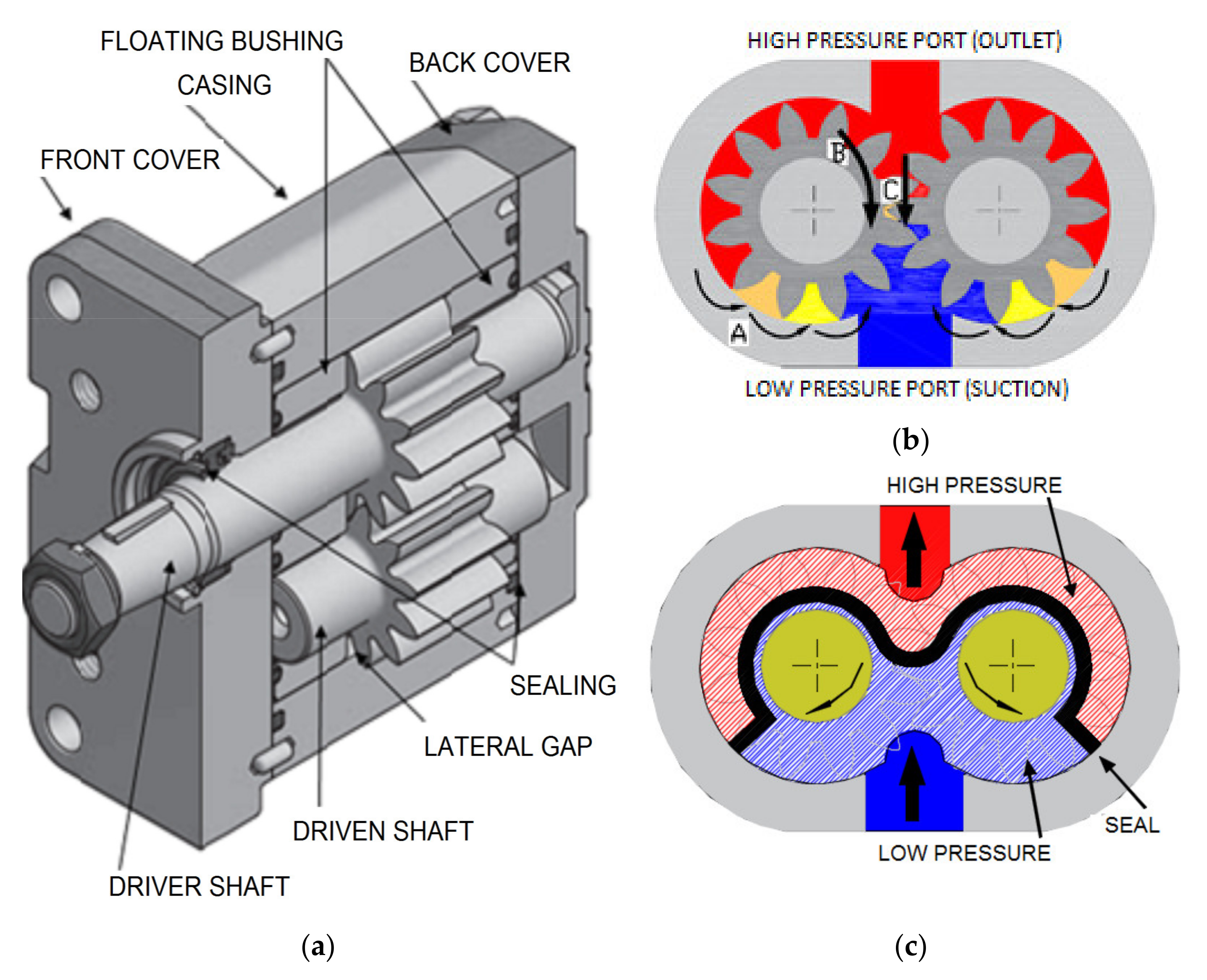
The reference number [0016] 10 (FIG. 1) generally designates a hydraulic pump assembly embodying the present invention. In the illustrated example, pump assembly 10 includes a pump housing 12 defining a chamber 14 (FIG. 2) therein. The chamber 14 includes a first cylindrically shaped portion 16 and a second cylindrically shaped portion 18. The housing 12 includes an inlet port 20 and an outlet port 22 (FIG. 3) each in fluid communication with chamber 14. Housing 12 further includes a first circulation port 24, a second circulation port 26 and a third circulation port 27, wherein first circulation port 24 is in fluid communication with first portion 16 of chamber 14, and second and third circulation ports 26 and 27 are in fluid communication with second portion 18 of chamber 14. Hydraulic pump assembly 10 further includes a first rotary pump element 28 and a second rotary pump element 30 disposed for rotation within first portion 16 and second portion 18 of chamber 14, respectively. The pump elements 28 and 30 cooperate to create a hydraulic pressure within chamber 14 of housing 12. Hydraulic pump assembly 10 further includes a drive shaft 32 and an idler shaft 34 disposed within portions 16 and 18 of chamber 14 and within pump elements 28 and 30. Drive shaft 32 and idler shaft 34 are fixed for rotation with respect to pump elements 28 and 30, respectively, and are further axially shiftable or linearly translatable with respect to pump elements 28 and 30. Drive shaft 32 and idler shaft 34 are axially supported by hydraulic fluid located within pockets 36 (FIG. 4) as described below.
In operation, and as described further below, inlet port [0017] 20 of housing 12 is in fluid communication with a source of hydraulic fluid such as a reservoir (not shown). The hydraulic fluid is drawn into chamber 14 via inlet port 20 by the rotational motion of pump elements 28 and 30 as drive shaft 32 is driven in rotation by a motor unit, or other source or other apparatus for imparting rotary motion to the pump, via an intermediate shaft 29. The hydraulic fluid is then forced outward from chamber 14 under hydraulic pressure via outlet port 22, which is in fluid communication with a system that utilizes the hydraulic pressure (not shown). The hydraulic fluid is then returned to the reservoir via a hydraulic fluid return port 37 that is in fluid communication with the reservoir.
The housing [0018] 12 of pump assembly 10 includes a circularly shaped wear plate 38. Wear plate 38 includes a plurality of apertures 40 spaced about a periphery of wear plate 38 and adapted to receive mounting hardware (not shown) therein to secure housing 12 of pump assembly 10 to the system utilizing the increased hydraulic pressure generated by pump assembly 10 and as provided through outlet port 22. Wear plate 38 is defined by a first side 42 and an oppositely facing second side 44. First side 42 includes a recessed area 46 that defines a recessed wall 48. Wear plate 38 also includes a portion 50 protruding outwardly from recessed wall 48. Portion 50 of wear plate 38 is defined by an outwardly extending wall 52 that extends substantially perpendicular to recessed wall 48, and a mating surface 54 that is substantially parallel with recessed wall 48. Portion 50 of wear plate 38 includes a plurality of inwardly extending, threaded apertures 56 that are adapted to threadably receive a plurality of bolts 58 therein, thereby securing sections of housing 12 together. Portion 50 of wear plate 38 further includes a first bore 60 and a second bore 62, having an end wall 71, adapted to receive a first end 61 of drive shaft 32 and a first end 63 of idler shaft 34 therein, respectively. Portion 50 of wear plate 38 further includes an end chamber 65 forming the end of an inlet chamber 67, and an intermediate shaft bore 66 that extends between second side 44 of wear plate 38 and first bore 60. Second side 44 of wear plate 38 includes a mounting surface 69 that extends about the periphery of wear plate 38 and further divides numerous apertures defined therein. Specifically, mounting surface 69 defines a first recessed area 70 that provides fluid communication between the hydraulic fluid reservoir and both the intermediate shaft bore 66 and circulation port 27. Mounting surface 69 further defines a second recessed area 74 surrounding and in fluid communication with return port 37.
The housing [0020] 12 also includes a cylinder plate or body 78 having a similar cross-sectional shape to that of portion 50 of wear plate 38, and is defined by an outer wall 80, a first mating surface 82 and a second mating surface 83 opposite first mating surface 82. Cylinder plate 78 includes a first circularly shaped passage 84 and a second circularly-shaped passage 86 that extend between first and second mating surfaces 82 and 83 of cylinder plate 78 and are adapted to rotatably receive first pump element 28 and second pump element 30 therein, respectively. First passage 84 and second passage 86 are in fluid communication with one another and cooperate to form a figure-8 shaped cross-sectional geometry. Cylinder plate 78 also includes an inlet passage 88 extending between first and second mating surface 82 and 83, and forming a portion of inlet chamber 67, and an outlet passage 90 extending between first and second mating surfaces 82 and 83 and forming a portion of an outlet chamber 69. Cylinder plate 78 further includes a plurality of apertures 92 adapted to receive bolts 58 therein and co-located with apertures 56 of wear plate 38 when housing 12 is assembled. Cylinder plate 78 further includes a pair of apertures 94 extending between first and second mating surfaces 82 and which are adapted to receive alignment pins 76 of wear plate 38 therein, thereby providing alignment between cylinder plate 78 and wear plate 38 during assembly of housing 12.
The housing [0021] 12 of pump assembly 10 further includes a suction or port plate 96 defined by an outer wall 98, an end wall 100, and a mating surface 102. Suction plate 96 is provided with a cross-sectional shape that is similar to that of portion 50 of wear plate 38. Suction plate 96 includes a first bore 104, having an end wall 109, and a second bore 106, having an end wall 111, adapted to receive a second end 105 of drive shaft 32 and a second end 107 of idler shaft 34 therein, respectively. Circulation ports 24 and 26 extend from end wall 100 of suction plate 96 to bores 104 and 106, respectively. Inlet port 20 extends between end wall 100 and mating surface 102 and is concentrically located with inlet passage 88 of cylinder plate 78 when housing 12 is assembled. Suction plate 96 is further provided with a plurality of apertures 110 adapted to receive bolts 58 therein and which are co-located with apertures 92 of cylinder plate 78 and apertures 56 of wear plate 38 when housing 12 is assembled.
The first and second pump elements [0022] 28 and 30 include a drive gear 112 and an idler gear 114, respectively. As drive gear 112 and idler gear 114 are similar in construction in relation to their respective shafts 32 and 34, the description of drive gear 112 should be considered descriptive of both drive gear 112 and idler gear 114. Drive gear 112 includes a central aperture 116 and a plurality of teeth 118 extending about a periphery thereof. Drive gear 112 further includes a leak path 120 which is defined as the distance between aperture 116 and the roots 122 of teeth 118. Gears 112 and 114 are keyed for rotational movement with respect to shafts 32 and 34 via keys 131, respectively. Gears 112 and 114 are not fixedly attached to shafts 32 and 34, thereby allowing shafts 32 and 34 to translate linearly with respect to gears 112 and 114.
The first end [0023] 61 of drive shaft 32 includes a wedge section 121 adapted to mate with intermediate shaft 29. Wedge section 121 is provided a substantially rectangular cross-sectional area. First end 63 and second end 107 of idler shaft 34, as well as second end 105 of drive shaft 32 each include a chamfered or rounded end face 123.
As pump assembly [0024] 10 operates, and as described further below, some of the hydraulic fluid that is forced between gears 112 and 114 leaks along the leak path 120 of each gear 112 and 114, and lubricates bearing 113. The overall efficiency of pump assembly 10 is, in part, maximized by maximizing the leak path 120 of each gear 112 and 114 to minimize oil blow-back into bores 60, 62, 104 and 106 while minimizing the overall size of gears 112 and 114. This is accomplished within pump assembly 10 by eliminating the retaining rings typically associated with the pump elements of hydraulic pumps. These retaining rings decrease pump efficiency by decreasing the leak path 120 of the pump elements, as well as by requiring increased tolerances due to manufacturing variances of the pump element components and the assembly thereof.
The intermediate shaft [0025] 29 couples drive shaft 32 with the motor unit (not shown), and includes a notched end 125 having a substantial rectangular cross-sectional area adapted to hingedly receive wedge section 121 of drive shaft 32 therein, and a wedge section 127 located at the opposite end of intermediate shaft 29. Wedge section 127 of drive shaft 29 has a rectangular cross-sectional area that extends substantially perpendicular to notched end 125. The wedge section/notched end connections between intermediate shaft 29 and drive shaft 32 allows pump assembly 10 to move with respect to the motor unit during operation without interrupting the connection therebetween.
Prior to the addition of suction plate [0027] 96 to housing 12, drive shaft 32 and drive gear 112, a plurality of bushings or journal bearings 113, idler shaft 34 and idler gear 114 are placed within chamber 14 of housing 12 such that first end 61 of drive shaft 32 extends into first bore 60 of wear plate 38, first end 63 of idler shaft 34 extends into second bore 62 of wear plate 38, drive gear 112 is concentrically located within first passage 84 of cylinder plate 78 and idler gear 114 is concentrically located within second passage 86 of cylinder plate 78. Suction plate 96 is then positioned with respect to cylinder plate 78 such that second end 105 of drive shaft 32 extends into first bore 104 suction plate 96 and second end 107 of idler shaft 34 extends into second bore 106 of suction plate 96.
In operation, a rotational force is exerted on drive shaft [0028] 34 by the motor unit (not shown) via intermediate shaft 29. As is well known in the art, the rotary motion and cooperation between power gear 112 and idler gear 114 create a suction pressure thereby drawing hydraulic fluid into inlet chamber 67 of housing 12 via inlet port 20. The hydraulic fluid is then forced into outlet chamber 69 by rotational movement of gears 112 and 114, and then out from housing 12 via outlet port 22 and into the system utilizing the increased hydraulic pressure. It should be noted that the operation of pump assembly 10 as described above, can be reversed by reversing the direction of rotation of gears 112 and 114 using suitably configured suction and wear plates. Fluid is then returned from the hydraulic system to the hydraulic fluid reservoir via hydraulic fluid return port 37. As hydraulic fluid is forced between gears 112 and 114, hydraulic fluid also leaks along the leak path 120 thereof, at a pressure that is different from both the inlet pressure and outlet pressure, and into first bores 60 and 104, and second bores 62 and 106 of chamber 14, thereby lubricating bearings 113. The hydraulic fluid traveling into bores 60, 62, 104 and 106 is typically referred to in the art as “leakage fluid.” The hydraulic fluid subsequently leaks into the ends of bores 62, 104 and 106, and into pockets 36 between the end walls 71, 109 and 111 of bores 62, 104 and 106, and shafts 32 and 34, thereby keeping ends 123 of shafts 32 and 34 in spaced apart relation to end walls 71, 109 and 111 of bores 62, 104 and 106. The hydraulic fluid located within pockets 36 eliminates the necessity of mechanical elements to restrict the axial translation of shafts 32 and 34. The hydraulic fluid located within pockets 36 prevents shafts 32 and 34 from 34 from contacting housing 12, thereby reducing friction and increasing the overall efficiency of pump 10 for a given set of operating parameters such as outlet pressure and flow rate. Further, the free axial translation of shafts 32 and 34 with respect to gears 112 and 114 allows shafts 32 and 34 to be located to an optimum operating position for a given set of geometrical parameters.
Circulation ports [0029] 24, 26 and 36 allow the hydraulic fluid flowing through bores 62, 104 and 106, and into pockets 36, to circulate back into the hydraulic fluid reservoir after providing proper lubrication of bearings 113 and equalization of pressure within bores 62, 104 and 106. It should be noted that circulation ports 24, 26 and 68 are not concentrically located with their respective bores 104, 106 and 62, and are therefore off-center from shafts 32 and 34. This allows hydraulic fluid to flow through circulation ports 24, 26 and 36 even if chamfered ends 123 of shafts 32 and 34 should contact housing 12 during starting. The non-concentric location of the circulation ports 24, 26 and 68 within bores 104,106 and 102 further ensures that a sufficient amount of hydraulic fluid is present within pockets 36 during operation of pump 10. The size of circulation ports 24, 26 and 36 are sized so as to restrict the flow of hydraulic fluid from within pockets 36, thereby creating a “back-pressure” on the ends 123 of shafts 32 and 34. It should further be noted that the size of ports 24, 26 and 36 are functions of variables such as required pump capacity and flow rate variations.
In another embodiment, pump [0030] 10 includes a pair of bearings 130 located within a pair of pockets 132. In operation, bearings 130 support shafts 32 and 34 when pump 10 is oriented such that ends 105 and 107 of shafts 32 and 34 are located below ends 61 and 63. It should be noted that shafts 32 and 34 are set apart from bearings 130 when pump 10 is in operation and hydraulic fluid is traveling through housing 12. The bearings 130 support shafts 32 and 34 thereon during start-up and shut-down of pump 10.
The reference numeral [0031] 10 a(FIGS. 6 and 7) generally designates another embodiment of the hydraulic pump. Since pump 10 ais similar to the previously described pump 10, similar parts appearing in FIGS. 1 and 3 and FIGS. 6 and 7, respectfully, are represented by the same, corresponding reference numeral, except for the suffix “a” in the numeral of the latter.
The hydraulic pump [0032] 10 ais similarly constructed and assembled as the hydraulic pump 10, with the most notable exception being the replacement of wear plate 38 with a reduced size wear plate 38 a.Wear plate 38 aincludes the plurality of apertures 40 aadapted to receive bolts 58 atherein, out let port 22 a,drive shaft bore 66 aadapted to receive drive shaft 29 atherein, and communication port 27 a.A longitudinally extending channel 126 provides fluid communication between communication port 27 aand drive shaft bore 66 awhen pump 10 ais in operation.
Hydraulic pump assembly [0033] 10 provides a greatly improved pump efficiency by eliminating the need for mechanical elements and/or retention devices such as retaining rings to attach gears 112 and 114 to shafts 32 and 34. By eliminating the need for retaining rings, pump elements 28 and 30 of pump assembly 10 are able to maintain a sufficiently large leak path 120 for a relatively smaller size of pump elements 28 and 30 and overall size of the associated pump 10 for a given set of operational parameters. Further, pump assembly 10 is more economical to produce, maintain and repair, and is particularly well adapted to applications requiring pumps of reduced size.
a pump housing having a chamber defined therein, the chamber including a pair of cylindrically shaped portions each defining at least one end wall, the housing including an inlet port and an outlet port in fluid communication with the chamber:
a pair of rotary pump elements disposed for rotation within the cylindrically shaped portions of the chamber, wherein the pair of pump elements cooperate to create a hydraulic pressure; and
a pair of cylindrically shaped shafts each having at least one end face, the shafts disposed within the pair of cylindrically shaped portions of the chamber and within the pair of pump elements, the shafts fixed for rotation and axially shiftable with respect to the pump elements;
wherein a hydraulic fluid within the chamber stabilizes at least one of the axially shiftable shafts such that the end face of the shaft is spaced from the associated end wall of the cylindrically shaped portion of the chamber when the hydraulic pump assembly is in use.
2. The hydraulic pump assembly of claim 1, wherein the housing further includes at least one circulation port in fluid communication with at least one of the cylindrically shaped portions of the chamber.
4. The hydraulic pump assembly of claim 3, wherein each of the shafts define a longitudinal axis, each of the cylindrically shaped portions of the chamber is in fluid commination with one of the circulation ports, and wherein each circulation port is offset from a longitudinal axes of the shafts.
5. The hydraulic pump assembly of claim 4, wherein the hydraulic pump further includes an intermediate shaft, the pair of shafts includes a first shaft and a second shaft, the first shaft having a first end and a second end, and wherein the first end of the first shaft is hingedly coupled with the drive shaft.
8. The hydraulic pump assembly of claim 7, wherein the housing includes a first section that includes a portion of each of the cylindrically shaped portions of the chamber, and a second section that includes a portion of each of the cylindrically shaped portions of the chamber.
11. The hydraulic pump assembly of claim 10, wherein each of the shafts define a longitudinal axis, each of the cylindrically shaped portions of the chamber is in fluid commination with one of the circulation ports, and wherein each circulation port is offset from the longitudinal axes of the shafts, thereby allowing hydraulic fluid to escape from the cylindrically shaped portions of the chamber via the circulation ports when the end faces of the shafts are in contact with the end walls of the cylindrically shaped portions of the chamber.
12. The hydraulic pump assembly of claim 1, wherein the hydraulic pump further includes an intermediate shaft, the pair of cylindrically shaped shafts includes a first shaft and a second shaft, the first shaft having a first end and a second end, and wherein the first end of the first shaft is hingedly coupled with the intermediate shaft.
14. The hydraulic pump assembly of claim 13, wherein the intermediate shaft has a C-shaped cross-sectional geometry that receives the drive shaft therein.
15. The hydraulic pump assembly of claim 1, wherein the housing includes a first section that includes a portion of each of the cylindrically shaped portions of the chamber, and a second section that includes a portion of each of the cylindrically shaped portions of the chamber.
16. The hydraulic pump assembly of claim 1, further including at least one bearing located within the cylindrical portions of the housing, wherein the bearing is adapted to axially support the associated first and second shaft during start-up and shut-down of the pump.
a pump housing having a chamber defined therein, the housing including an inlet port, an outlet port and at least one circulation port in fluid communication with the chamber, the chamber including a pair of cylindrically shaped portions each having at least one end wall;
a pair of rotary pump elements each having a central bore extending therethrough and a plurality of meshing teeth, the pump elements disposed for rotation within the chamber, the pair of pump elements cooperating to create a hydraulic pressure within a portion of the chamber; and
a pair of cylindrically shaped shafts each having at least one end face, the shafts disposed within the chamber and within the central bores of the pump elements, the shafts fixed for rotation and linearly translatable with respect to the pump elements;
wherein a hydraulic fluid within the hydraulic pump assembly stabilizes at least one linearly translatable shaft such that the end face of the shafts is spaced apart from the associated end wall of the cylindrically shaped portions of the chamber when the pump assembly is in use.
18. The hydraulic pump assembly of claim 17, wherein the circulation ports are configured to optimize a hydraulic pressure within the cylindrically shaped portions of the chamber.
20. The hydraulic pump assembly of claim 19, wherein each of the shafts defines a longitudinal axis, each of the cylindrically shaped portions of the chamber houses one of the shafts therein, and wherein each circulation port is offset from the longitudinal axes of the shafts, thereby allowing hydraulic fluid to escape from the cylindrically shaped portions of the chamber via the circulation ports when the end faces of the shafts are in contact with the end walls of the cylindrically shaped portions of the chamber.
21. The hydraulic pump assembly of claim 17, wherein the hydraulic pump further includes an intermediate shaft, the pair of cylindrically shaped shafts includes a first shaft and a second shaft, the first shaft having a first end and a second end, and wherein the first end of the first shaft is hingedly coupled with the intermediate shaft.
23. The hydraulic pump assembly of claim 22, wherein the intermediate shaft has a C-shaped cross-sectional geometry that receives the drive shaft therein.
24. The hydraulic pump assembly of claim 22, wherein the housing includes a first section that includes a portion of each of the cylindrically shaped portions of the chamber, and a second section that includes a portion of each of the cylindrically shaped portions of the chamber.
26. The hydraulic pump assembly of claim 17, further including at least one bearing located within the cylindrical portions of the housing, wherein the bearing is adapted to axially support the associated first and second shaft during start-up and shut-down of the pump.
Gear ring pump including housing containing port support therein with the port support formed of a material having a greater heat expansion coefficient than a material of the housing

Hydraulic pumps are mechanisms in hydraulic systems that move hydraulic fluid from point to point initiating the production of hydraulic power. Hydraulic pumps are sometimes incorrectly referred to as “hydrolic” pumps.
They are an important device overall in the hydraulics field, a special kind of power transmission which controls the energy which moving fluids transmit while under pressure and change into mechanical energy. Other kinds of pumps utilized to transmit hydraulic fluids could also be referred to as hydraulic pumps. There is a wide range of contexts in which hydraulic systems are applied, hence they are very important in many commercial, industrial, and consumer utilities.
“Power transmission” alludes to the complete procedure of technologically changing energy into a beneficial form for practical applications. Mechanical power, electrical power, and fluid power are the three major branches that make up the power transmission field. Fluid power covers the usage of moving gas and moving fluids for the transmission of power. Hydraulics are then considered as a sub category of fluid power that focuses on fluid use in opposition to gas use. The other fluid power field is known as pneumatics and it’s focused on the storage and release of energy with compressed gas.
"Pascal"s Law" applies to confined liquids. Thus, in order for liquids to act hydraulically, they must be contained within a system. A hydraulic power pack or hydraulic power unit is a confined mechanical system that utilizes liquid hydraulically. Despite the fact that specific operating systems vary, all hydraulic power units share the same basic components. A reservoir, valves, a piping/tubing system, a pump, and actuators are examples of these components. Similarly, despite their versatility and adaptability, these mechanisms work together in related operating processes at the heart of all hydraulic power packs.
The hydraulic reservoir"s function is to hold a volume of liquid, transfer heat from the system, permit solid pollutants to settle, and aid in releasing moisture and air from the liquid.
Mechanical energy is changed to hydraulic energy by the hydraulic pump. This is accomplished through the movement of liquid, which serves as the transmission medium. All hydraulic pumps operate on the same basic principle of dispensing fluid volume against a resistive load or pressure.
Hydraulic valves are utilized to start, stop, and direct liquid flow in a system. Hydraulic valves are made of spools or poppets and can be actuated hydraulically, pneumatically, manually, electrically, or mechanically.
The end result of Pascal"s law is hydraulic actuators. This is the point at which hydraulic energy is transformed back to mechanical energy. This can be accomplished by using a hydraulic cylinder to transform hydraulic energy into linear movement and work or a hydraulic motor to transform hydraulic energy into rotational motion and work. Hydraulic motors and hydraulic cylinders, like hydraulic pumps, have various subtypes, each meant for specific design use.
The essence of hydraulics can be found in a fundamental physical fact: fluids are incompressible. (As a result, fluids more closely resemble solids than compressible gasses) The incompressible essence of fluid allows it to transfer force and speed very efficiently. This fact is summed up by a variant of "Pascal"s Principle," which states that virtually all pressure enforced on any part of a fluid is transferred to every other part of the fluid. This scientific principle states, in other words, that pressure applied to a fluid transmits equally in all directions.
Furthermore, the force transferred through a fluid has the ability to multiply as it moves. In a slightly more abstract sense, because fluids are incompressible, pressurized fluids should keep a consistent pressure just as they move. Pressure is defined mathematically as a force acting per particular area unit (P = F/A). A simplified version of this equation shows that force is the product of area and pressure (F = P x A). Thus, by varying the size or area of various parts inside a hydraulic system, the force acting inside the pump can be adjusted accordingly (to either greater or lesser). The need for pressure to remain constant is what causes force and area to mirror each other (on the basis of either shrinking or growing). A hydraulic system with a piston five times larger than a second piston can demonstrate this force-area relationship. When a force (e.g., 50lbs) is exerted on the smaller piston, it is multiplied by five (e.g., 250 lbs) and transmitted to the larger piston via the hydraulic system.
Hydraulics is built on fluids’ chemical properties and the physical relationship between pressure, area, and force. Overall, hydraulic applications allow human operators to generate and exert immense mechanical force with little to no physical effort. Within hydraulic systems, both oil and water are used to transmit power. The use of oil, on the other hand, is far more common, owing in part to its extremely incompressible nature.
Pressure relief valves prevent excess pressure by regulating the actuators’ output and redirecting liquid back to the reservoir when necessary. Directional control valves are used to change the size and direction of hydraulic fluid flow.
While hydraulic power transmission is remarkably useful in a wide range of professional applications, relying solely on one type of power transmission is generally unwise. On the contrary, the most efficient strategy is to combine a wide range of power transmissions (pneumatic, hydraulic, mechanical, and electrical). As a result, hydraulic systems must be carefully embedded into an overall power transmission strategy for the specific commercial application. It is necessary to invest in locating trustworthy and skilled hydraulic manufacturers/suppliers who can aid in the development and implementation of an overall hydraulic strategy.
The intended use of a hydraulic pump must be considered when selecting a specific type. This is significant because some pumps may only perform one function, whereas others allow for greater flexibility.
The pump"s material composition must also be considered in the application context. The cylinders, pistons, and gears are frequently made of long-lasting materials like aluminum, stainless steel, or steel that can withstand the continuous wear of repeated pumping. The materials must be able to withstand not only the process but also the hydraulic fluids. Composite fluids frequently contain oils, polyalkylene glycols, esters, butanol, and corrosion inhibitors (though water is used in some instances). The operating temperature, flash point, and viscosity of these fluids differ.
In addition to material, manufacturers must compare hydraulic pump operating specifications to make sure that intended utilization does not exceed pump abilities. The many variables in hydraulic pump functionality include maximum operating pressure, continuous operating pressure, horsepower, operating speed, power source, pump weight, and maximum fluid flow. Standard measurements like length, rod extension, and diameter should be compared as well. Because hydraulic pumps are used in lifts, cranes, motors, and other heavy machinery, they must meet strict operating specifications.
It is critical to recall that the overall power generated by any hydraulic drive system is influenced by various inefficiencies that must be considered in order to get the most out of the system. The presence of air bubbles within a hydraulic drive, for example, is known for changing the direction of the energy flow inside the system (since energy is wasted on the way to the actuators on bubble compression). Using a hydraulic drive system requires identifying shortfalls and selecting the best parts to mitigate their effects. A hydraulic pump is the "generator" side of a hydraulic system that initiates the hydraulic procedure (as opposed to the "actuator" side that completes the hydraulic procedure). Regardless of disparities, all hydraulic pumps are responsible for displacing liquid volume and transporting it to the actuator(s) from the reservoir via the tubing system. Some form of internal combustion system typically powers pumps.
While the operation of hydraulic pumps is normally the same, these mechanisms can be split into basic categories. There are two types of hydraulic pumps to consider: gear pumps and piston pumps. Radial and axial piston pumps are types of piston pumps. Axial pumps produce linear motion, whereas radial pumps can produce rotary motion. The gear pump category is further subdivided into external gear pumps and internal gear pumps.
Each type of hydraulic pump, regardless of piston or gear, is either double-action or single-action. Single-action pumps can only pull, push, or lift in one direction, while double-action pumps can pull, push, or lift in multiple directions.
Vane pumps are positive displacement pumps that maintain a constant flow rate under varying pressures. It is a pump that self-primes. It is referred to as a "vane pump" because the effect of the vane pressurizes the liquid.
This pump has a variable number of vanes mounted onto a rotor that rotates within the cavity. These vanes may be variable in length and tensioned to maintain contact with the wall while the pump draws power. The pump also features a pressure relief valve, which prevents pressure rise inside the pump from damaging it.
Internal gear pumps and external gear pumps are the two main types of hydraulic gear pumps. Pumps with external gears have two spur gears, the spurs of which are all externally arranged. Internal gear pumps also feature two spur gears, and the spurs of both gears are internally arranged, with one gear spinning around inside the other.
Both types of gear pumps deliver a consistent amount of liquid with each spinning of the gears. Hydraulic gear pumps are popular due to their versatility, effectiveness, and fairly simple design. Furthermore, because they are obtainable in a variety of configurations, they can be used in a wide range of consumer, industrial, and commercial product contexts.
Hydraulic ram pumps are cyclic machines that use water power, also referred to as hydropower, to transport water to a higher level than its original source. This hydraulic pump type is powered solely by the momentum of moving or falling water.
Ram pumps are a common type of hydraulic pump, especially among other types of hydraulic water pumps. Hydraulic ram pumps are utilized to move the water in the waste management, agricultural, sewage, plumbing, manufacturing, and engineering industries, though only about ten percent of the water utilized to run the pump gets to the planned end point.
Despite this disadvantage, using hydropower instead of an external energy source to power this kind of pump makes it a prominent choice in developing countries where the availability of the fuel and electricity required to energize motorized pumps is limited. The use of hydropower also reduces energy consumption for industrial factories and plants significantly. Having only two moving parts is another advantage of the hydraulic ram, making installation fairly simple in areas with free falling or flowing water. The water amount and the rate at which it falls have an important effect on the pump"s success. It is critical to keep this in mind when choosing a location for a pump and a water source. Length, size, diameter, minimum and maximum flow rates, and speed of operation are all important factors to consider.
Hydraulic water pumps are machines that move water from one location to another. Because water pumps are used in so many different applications, there are numerous hydraulic water pump variations.
Water pumps are useful in a variety of situations. Hydraulic pumps can be used to direct water where it is needed in industry, where water is often an ingredient in an industrial process or product. Water pumps are essential in supplying water to people in homes, particularly in rural residences that are not linked to a large sewage circuit. Water pumps are required in commercial settings to transport water to the upper floors of high rise buildings. Hydraulic water pumps in all of these situations could be powered by fuel, electricity, or even by hand, as is the situation with hydraulic hand pumps.
Water pumps in developed economies are typically automated and powered by electricity. Alternative pumping tools are frequently used in developing economies where dependable and cost effective sources of electricity and fuel are scarce. Hydraulic ram pumps, for example, can deliver water to remote locations without the use of electricity or fuel. These pumps rely solely on a moving stream of water’s force and a properly configured number of valves, tubes, and compression chambers.
Electric hydraulic pumps are hydraulic liquid transmission machines that use electricity to operate. They are frequently used to transfer hydraulic liquid from a reservoir to an actuator, like a hydraulic cylinder. These actuation mechanisms are an essential component of a wide range of hydraulic machinery.
There are several different types of hydraulic pumps, but the defining feature of each type is the use of pressurized fluids to accomplish a job. The natural characteristics of water, for example, are harnessed in the particular instance of hydraulic water pumps to transport water from one location to another. Hydraulic gear pumps and hydraulic piston pumps work in the same way to help actuate the motion of a piston in a mechanical system.
Despite the fact that there are numerous varieties of each of these pump mechanisms, all of them are powered by electricity. In such instances, an electric current flows through the motor, which turns impellers or other devices inside the pump system to create pressure differences; these differential pressure levels enable fluids to flow through the pump. Pump systems of this type can be utilized to direct hydraulic liquid to industrial machines such as commercial equipment like elevators or excavators.
Hydraulic hand pumps are fluid transmission machines that utilize the mechanical force generated by a manually operated actuator. A manually operated actuator could be a lever, a toggle, a handle, or any of a variety of other parts. Hydraulic hand pumps are utilized for hydraulic fluid distribution, water pumping, and various other applications.
Hydraulic hand pumps may be utilized for a variety of tasks, including hydraulic liquid direction to circuits in helicopters and other aircraft, instrument calibration, and piston actuation in hydraulic cylinders. Hydraulic hand pumps of this type use manual power to put hydraulic fluids under pressure. They can be utilized to test the pressure in a variety of devices such as hoses, pipes, valves, sprinklers, and heat exchangers systems. Hand pumps are extraordinarily simple to use.
Each hydraulic hand pump has a lever or other actuation handle linked to the pump that, when pulled and pushed, causes the hydraulic liquid in the pump"s system to be depressurized or pressurized. This action, in the instance of a hydraulic machine, provides power to the devices to which the pump is attached. The actuation of a water pump causes the liquid to be pulled from its source and transferred to another location. Hydraulic hand pumps will remain relevant as long as hydraulics are used in the commerce industry, owing to their simplicity and easy usage.
12V hydraulic pumps are hydraulic power devices that operate on 12 volts DC supplied by a battery or motor. These are specially designed processes that, like all hydraulic pumps, are applied in commercial, industrial, and consumer places to convert kinetic energy into beneficial mechanical energy through pressurized viscous liquids. This converted energy is put to use in a variety of industries.
Hydraulic pumps are commonly used to pull, push, and lift heavy loads in motorized and vehicle machines. Hydraulic water pumps may also be powered by 12V batteries and are used to move water out of or into the desired location. These electric hydraulic pumps are common since they run on small batteries, allowing for ease of portability. Such portability is sometimes required in waste removal systems and vehiclies. In addition to portable and compact models, options include variable amp hour productions, rechargeable battery pumps, and variable weights.
While non rechargeable alkaline 12V hydraulic pumps are used, rechargeable ones are much more common because they enable a continuous flow. More considerations include minimum discharge flow, maximum discharge pressure, discharge size, and inlet size. As 12V batteries are able to pump up to 150 feet from the ground, it is imperative to choose the right pump for a given use.
Air hydraulic pumps are hydraulic power devices that use compressed air to stimulate a pump mechanism, generating useful energy from a pressurized liquid. These devices are also known as pneumatic hydraulic pumps and are applied in a variety of industries to assist in the lifting of heavy loads and transportation of materials with minimal initial force.
Air pumps, like all hydraulic pumps, begin with the same components. The hydraulic liquids, which are typically oil or water-based composites, require the use of a reservoir. The fluid is moved from the storage tank to the hydraulic cylinder via hoses or tubes connected to this reservoir. The hydraulic cylinder houses a piston system and two valves. A hydraulic fluid intake valve allows hydraulic liquid to enter and then traps it by closing. The discharge valve is the point at which the high pressure fluid stream is released. Air hydraulic pumps have a linked air cylinder in addition to the hydraulic cylinder enclosing one end of the piston.
The protruding end of the piston is acted upon by a compressed air compressor or air in the cylinder. When the air cylinder is empty, a spring system in the hydraulic cylinder pushes the piston out. This makes a vacuum, which sucks fluid from the reservoir into the hydraulic cylinder. When the air compressor is under pressure, it engages the piston and pushes it deeper into the hydraulic cylinder and compresses the liquids. This pumping action is repeated until the hydraulic cylinder pressure is high enough to forcibly push fluid out through the discharge check valve. In some instances, this is connected to a nozzle and hoses, with the important part being the pressurized stream. Other uses apply the energy of this stream to pull, lift, and push heavy loads.
Hydraulic piston pumps transfer hydraulic liquids through a cylinder using plunger-like equipment to successfully raise the pressure for a machine, enabling it to pull, lift, and push heavy loads. This type of hydraulic pump is the power source for heavy-duty machines like excavators, backhoes, loaders, diggers, and cranes. Piston pumps are used in a variety of industries, including automotive, aeronautics, power generation, military, marine, and manufacturing, to mention a few.
Hydraulic piston pumps are common due to their capability to enhance energy usage productivity. A hydraulic hand pump energized by a hand or foot pedal can convert a force of 4.5 pounds into a load-moving force of 100 pounds. Electric hydraulic pumps can attain pressure reaching 4,000 PSI. Because capacities vary so much, the desired usage pump must be carefully considered. Several other factors must also be considered. Standard and custom configurations of operating speeds, task-specific power sources, pump weights, and maximum fluid flows are widely available. Measurements such as rod extension length, diameter, width, and height should also be considered, particularly when a hydraulic piston pump is to be installed in place of a current hydraulic piston pump.
Hydraulic clutch pumps are mechanisms that include a clutch assembly and a pump that enables the user to apply the necessary pressure to disengage or engage the clutch mechanism. Hydraulic clutches are crafted to either link two shafts and lock them together to rotate at the same speed or detach the shafts and allow them to rotate at different speeds as needed to decelerate or shift gears.
Hydraulic pumps change hydraulic energy to mechanical energy. Hydraulic pumps are particularly designed machines utilized in commercial, industrial, and residential areas to generate useful energy from different viscous liquids pressurization. Hydraulic pumps are exceptionally simple yet effective machines for moving fluids. "Hydraulic" is actually often misspelled as "Hydralic". Hydraulic pumps depend on the energy provided by hydraulic cylinders to power different machines and mechanisms.
There are several different types of hydraulic pumps, and all hydraulic pumps can be split into two primary categories. The first category includes hydraulic pumps that function without the assistance of auxiliary power sources such as electric motors and gas. These hydraulic pump types can use the kinetic energy of a fluid to transfer it from one location to another. These pumps are commonly called ram pumps. Hydraulic hand pumps are never regarded as ram pumps, despite the fact that their operating principles are similar.
The construction, excavation, automotive manufacturing, agriculture, manufacturing, and defense contracting industries are just a few examples of operations that apply hydraulics power in normal, daily procedures. Since hydraulics usage is so prevalent, hydraulic pumps are unsurprisingly used in a wide range of machines and industries. Pumps serve the same basic function in all contexts where hydraulic machinery is used: they transport hydraulic fluid from one location to another in order to generate hydraulic energy and pressure (together with the actuators).
Elevators, automotive brakes, automotive lifts, cranes, airplane flaps, shock absorbers, log splitters, motorboat steering systems, garage jacks and other products use hydraulic pumps. The most common application of hydraulic pumps in construction sites is in big hydraulic machines and different types of "off-highway" equipment such as excavators, dumpers, diggers, and so on. Hydraulic systems are used in other settings, such as offshore work areas and factories, to power heavy machinery, cut and bend material, move heavy equipment, and so on.
Fluid’s incompressible nature in hydraulic systems allows an operator to make and apply mechanical power in an effective and efficient way. Practically all force created in a hydraulic system is applied to the intended target.
Because of the relationship between area, pressure, and force (F = P x A), modifying the force of a hydraulic system is as simple as changing the size of its components.
Hydraulic systems can transfer energy on an equal level with many mechanical and electrical systems while being significantly simpler in general. A hydraulic system, for example, can easily generate linear motion. On the contrary, most electrical and mechanical power systems need an intermediate mechanical step to convert rotational motion to linear motion.
Hydraulic systems are typically smaller than their mechanical and electrical counterparts while producing equivalents amounts of power, providing the benefit of saving physical space.
Hydraulic systems can be used in a wide range of physical settings due to their basic design (a pump attached to actuators via some kind of piping system). Hydraulic systems could also be utilized in environments where electrical systems would be impractical (for example underwater).
By removing electrical safety hazards, using hydraulic systems instead of electrical power transmission improves relative safety (for example explosions, electric shock).
The amount of power that hydraulic pumps can generate is a significant, distinct advantage. In certain cases, a hydraulic pump could generate ten times the power of an electrical counterpart. Some hydraulic pumps (for example, piston pumps) cost more than the ordinary hydraulic component. These drawbacks, however, can be mitigated by the pump"s power and efficiency. Despite their relatively high cost, piston pumps are treasured for their strength and capability to transmit very viscous fluids.
Handling hydraulic liquids is messy, and repairing leaks in a hydraulic pump can be difficult. Hydraulic liquid that leaks in hot areas may catch fire. Hydraulic lines that burst may cause serious injuries. Hydraulic liquids are corrosive as well, though some are less so than others. Hydraulic systems need frequent and intense maintenance. Parts with a high factor of precision are frequently required in systems. If the power is very high and the pipeline cannot handle the power transferred by the liquid, the high pressure received by the liquid may also cause work accidents.
Even though hydraulic systems are less complex than electrical or mechanical systems, they are still complex systems that should be handled with caution. Avoiding physical contact with hydraulic systems is an essential safety precaution when engaging with them. Even when a hydraulic machine is not in use, active liquid pressure within the system can be a hazard.
Inadequate pumps can cause mechanical failure in the place of work that can have serious and costly consequences. Although pump failure has historically been unpredictable, new diagnostic technology continues to improve on detecting methods that previously relied solely on vibration signals. Measuring discharge pressures enables manufacturers to forecast pump wear more accurately. Discharge sensors are simple to integrate into existing systems, increasing the hydraulic pump"s safety and versatility.
Hydraulic pumps are devices in hydraulic systems that move hydraulic fluid from point to point, initiating hydraulic power production. They are an important device overall in the hydraulics field, a special kind of power transmission that controls the energy which moving fluids transmit while under pressure and change into mechanical energy. Hydraulic pumps are divided into two categories namely gear pumps and piston pumps. Radial and axial piston pumps are types of piston pumps. Axial pumps produce linear motion, whereas radial pumps can produce rotary motion. The construction, excavation, automotive manufacturing, agriculture, manufacturing, and defense contracting industries are just a few examples of operations that apply hydraulics power in normal, daily procedures.
A gear pump is a type of positive displacement (PD) pump. It moves a fluid by repeatedly enclosing a fixed volume using interlocking cogs or gears, transferring it mechanically using a cyclic pumping action. It delivers a smooth pulse-free flow proportional to the rotational speed of its gears.
Gear pumps use the actions of rotating cogs or gears to transfer fluids. The rotating element develops a liquid seal with the pump casing and creates suction at the pump inlet. Fluid, drawn into the pump, is enclosed within the cavities of its rotating gears and transferred to the discharge. There are two basic designs of gear pump: external and internal(Figure 1).
An external gear pump consists of two identical, interlocking gears supported by separate shafts. Generally, one gear is driven by a motor and this drives the other gear (the idler). In some cases, both shafts may be driven by motors. The shafts are supported by bearings on each side of the casing.
As the gears come out of mesh on the inlet side of the pump, they create an expanded volume. Liquid flows into the cavities and is trapped by the gear teeth as the gears continue to rotate against the pump casing.
No fluid is transferred back through the centre, between the gears, because they are interlocked. Close tolerances between the gears and the casing allow the pump to develop suction at the inlet and prevent fluid from leaking back from the discharge side (although leakage is more likely with low viscosity liquids).
An internal gear pump operates on the same principle but the two interlocking gears are of different sizes with one rotating inside the other. The larger gear (the rotor) is an internal gear i.e. it has the teeth projecting on the inside. Within this is a smaller external gear (the idler –only the rotor is driven) mounted off-centre. This is designed to interlock with the rotor such that the gear teeth engage at one point. A pinion and bushing attached to the pump casing holds the idler in position. A fixed crescent-shaped partition or spacer fills the void created by the off-centre mounting position of the idler and acts as a seal between the inlet and outlet ports.
As the gears come out of mesh on the inlet side of the pump, they create an expanded volume. Liquid flows into the cavities and is trapped by the gear teeth as the gears continue to rotate against the pump casing and partition.
Gear pumps are compact and simple with a limited number of moving parts. They are unable to match the pressure generated by reciprocating pumps or the flow rates of centrifugal pumps but offer higher pressures and throughputs than vane or lobe pumps. Gear pumps are particularly suited for pumping oils and other high viscosity fluids.
Of the two designs, external gear pumps are capable of sustaining higher pressures (up to 3000 psi) and flow rates because of the more rigid shaft support and closer tolerances. Internal gear pumps have better suction capabilities and are suited to high viscosity fluids, although they have a useful operating range from 1cP to over 1,000,000cP. Since output is directly proportional to rotational speed, gear pumps are commonly used for metering and blending operations. Gear pumps can be engineered to handle aggressive liquids. While they are commonly made from cast iron or stainless steel, new alloys and composites allow the pumps to handle corrosive liquids such as sulphuric acid, sodium hypochlorite, ferric chloride and sodium hydroxide.
External gear pumps can also be used in hydraulic power applications, typically in vehicles, lifting machinery and mobile plant equipment. Driving a gear pump in reverse, using oil pumped from elsewhere in a system (normally by a tandem pump in the engine), creates a hydraulic motor. This is particularly useful to provide power in areas where electrical equipment is bulky, costly or inconvenient. Tractors, for example, rely on engine-driven external gear pumps to power their services.
Gear pumps are self-priming and can dry-lift although their priming characteristics improve if the gears are wetted. The gears need to be lubricated by the pumped fluid and should not be run dry for prolonged periods. Some gear pump designs can be run in either direction so the same pump can be used to load and unload a vessel, for example.
The close tolerances between the gears and casing mean that these types of pump are susceptible to wear particularly when used with abrasive fluids or feeds containing entrained solids. However, some designs of gear pumps, particularly internal variants, allow the handling of solids. External gear pumps have four bearings in the pumped medium, and tight tolerances, so are less suited to handling abrasive fluids. Internal gear pumps are more robust having only one bearing (sometimes two) running in the fluid. A gear pump should always have a strainer installed on the suction side to protect it from large, potentially damaging, solids.
Generally, if the pump is expected to handle abrasive solids it is advisable to select a pump with a higher capacity so it can be operated at lower speeds to reduce wear. However, it should be borne in mind that the volumetric efficiency of a gear pump is reduced at lower speeds and flow rates. A gear pump should not be operated too far from its recommended speed.
For high temperature applications, it is important to ensure that the operating temperature range is compatible with the pump specification. Thermal expansion of the casing and gears reduces clearances within a pump and this can also lead to increased wear, and in extreme cases, pump failure.
Despite the best precautions, gear pumps generally succumb to wear of the gears, casing and bearings over time. As clearances increase, there is a gradual reduction in efficiency and increase in flow slip: leakage of the pumped fluid from the discharge back to the suction side. Flow slip is proportional to the cube of the clearance between the cog teeth and casing so, in practice, wear has a small effect until a critical point is reached, from which performance degrades rapidly.
Gear pumps continue to pump against a back pressure and, if subjected to a downstream blockage will continue to pressurise the system until the pump, pipework or other equipment fails. Although most gear pumps are equipped with relief valves for this reason, it is always advisable to fit relief valves elsewhere in the system to protect downstream equipment.
Internal gear pumps, operating at low speed, are generally preferred for shear-sensitive liquids such as foodstuffs, paint and soaps. The higher speeds and lower clearances of external gear designs make them unsuitable for these applications. Internal gear pumps are also preferred when hygiene is important because of their mechanical simplicity and the fact that they are easy to strip down, clean and reassemble.
Gear pumps are commonly used for pumping high viscosity fluids such as oil, paints, resins or foodstuffs. They are preferred in any application where accurate dosing or high pressure output is required. The output of a gear pump is not greatly affected by pressure so they also tend to be preferred in any situation where the supply is irregular.
A gear pump moves a fluid by repeatedly enclosing a fixed volume within interlocking cogs or gears, transferring it mechanically to deliver a smooth pulse-free flow proportional to the rotational speed of its gears. There are two basic types: external and internal. An external gear pump consists of two identical, interlocking gears supported by separate shafts. An internal gear pump has two interlocking gears of different sizes with one rotating inside the other.
Gear pumps are commonly used for pumping high viscosity fluids such as oil, paints, resins or foodstuffs. They are also preferred in applications where accurate dosing or high pressure output is required. External gear pumps are capable of sustaining higher pressures (up to 7500 psi) whereas internal gear pumps have better suction capabilities and are more suited to high viscosity and shear-sensitive fluids.
Check that the pump shaft is rotating. Even though coupling guards and C-face mounts can make this difficult to confirm, it is important to establish if your pump shaft is rotating. If it isn’t, this could be an indication of a more severe issue, and this should be investigated immediately.
Check the oil level. This one tends to be the more obvious check, as it is often one of the only factors inspected before the pump is changed. The oil level should be three inches above the pump suction. Otherwise, a vortex can form in the reservoir, allowing air into the pump.
What does the pump sound like when it is operating normally? Vane pumps generally are quieter than piston and gear pumps. If the pump has a high-pitched whining sound, it most likely is cavitating. If it has a knocking sound, like marbles rattling around, then aeration is the likely cause.
Cavitation is the formation and collapse of air cavities in the liquid. When the pump cannot get the total volume of oil it needs, cavitation occurs. Hydraulic oil contains approximately nine percent dissolved air. When the pump does not receive adequate oil volume at its suction port, high


 8613371530291