
simple hydraulic pump supplier

Use our thorough list of hydraulic pump manufacturers and suppliers in order to examine and sort top hydraulic pump manufacturers with previews of ads and detailed descriptions of each product. Any hydraulic pump manufacturers can provide hydraulic pump products and services to meet your companies specific qualifications. An easy connection to reach hydraulic pump manufacturers through our fast request for quote form is provided as well. This source is right for you whether it"s for hydraulic pump, 12V pump, flow control products or any other hydraulic pump needs.<

Hydraulic pumps (sometimes erroneously referred to as "hydrolic" pumps) are devices within hydraulic systems that transport hydraulic liquids from one point to another to initiate the creation of hydraulic power. They are an important component overall in the field of hydraulics, a specialized form of power transmission that harnesses the energy transmitted by moving liquids under pressure and converts it into mechanical energy. Other types of pumps that are used to transmit hydraulic fluids may also be called hydraulic pumps. Because of the wide variety of contexts in which hydraulic systems are employed, hydraulic pumps are very important in various industrial, commercial and consumer utilities.
The term power transmission refers to the overall process of technologically converting energy into a useful form for practical applications. Three main branches compose the field of power transmission: electrical power, mechanical power, and fluid power. Fluid power encompasses the use of moving gases and well as moving liquids for power transmission. Hydraulics, then, can be considered as a sub-branch of fluid power which focuses on liquid usage as opposed to gas usage. The other field of fluid power is known as pneumatics and revolves around storing and releasing energy with compressed gas.
As described above, the incompressible nature of fluid within hydraulic systems enables an operator to create and apply mechanical power in a very efficient manner. Practically all of the force generated within a hydraulic system is applied to its intended target.
Because of the relationship between force, area, and pressure (F = P x A), it is relatively easy to modify the force of a hydraulic system simply by modifying the size of its components.
Hydraulic systems can transmit power on par with many electrical and mechanical systems while being generally simpler at the same time. For example, it is easy to directly create linear motion with a hydraulic system. On the contrary, electrical and mechanical power systems generally require an intermediate mechanical step to produce linear motion from rotational motion.
Hydraulic power systems are generally smaller than their electrical and mechanical counterparts while generating similar amounts of power, thus providing the advantage of conserving physical space.
The basic design of hydraulic systems (a reservoir/pump connected to actuators by some sort of piping system) allows them to be used in a wide variety of physical settings. Hydraulic systems can also be used in environments that are impractical for electrical systems (e.g. underwater).
Using hydraulic systems in place of electrical power transmission increases relative safety by eliminating electrical safety hazards (e.g. explosions, electric shock).
A major, specific advantage of hydraulic pumps is the amount of power they are able to generate. In some cases, a hydraulic pump can produce ten times the amount of power produced by an electrical counterpart. Some types of hydraulic pumps (e.g. piston pumps) are more expensive than the average hydraulic component. These types of disadvantages, however, may be offset by the pump’s power and efficiency. For example, piston pumps are prized for their durability and ability to transmit very viscous fluids, despite their relatively high cost.
The essence of hydraulics lies in a fundamental physical reality: liquids are incompressible. Because of this, liquids resemble solids more than compressible gases. The incompressible nature of liquid enables it to transmit force very efficiently in terms of force and speed. This fact is summarized by a version of "Pascal’s Law" or "Pascal’s Principle", which states that virtually all of the pressure applied to any part of a (confined) fluid will be transmitted to every other part of the fluid. Using alternative terms, this scientific principle states that pressure exerted on a (confined) fluid transmits equally in every direction.
Furthermore, force transmitted within a fluid has the potential to multiply during its transmission. From a slightly more abstract point of view, the incompressible nature of liquids means that pressurized liquids must maintain a constant pressure even as they move. Pressure, from a mathematical point of view, is force acting per a specific area unit (P = F/A). A rearranged version of this equation makes it clear that force equals the product of pressure times area (F = P x A). Thus, by modifying the size or area of certain components within a hydraulic system, the force acting within a hydraulic system can also be modified accordingly (to either greater or lesser). The need for pressure to stay constant is responsible for making force and area reflect each other (in terms of either growing or shrinking). This force-area relationship can be illustrated by a hydraulic system containing a piston that is five times bigger than a second piston. if a certain force (e.g. 50 pounds) is applied to the smaller piston, that force will be multiplied by five (e.g. to 250 pounds) as it is transmitted to the larger piston within the hydraulic system.
The chemical nature of liquids as well as the physical relationship between force, area, and pressure form the foundation of hydraulics. Overall, hydraulic applications enable human operators to create and apply massive mechanical forces without exerting much physical effort at all. Water and oil are both used for power transmission within hydraulic systems. The use of oil, however, is far more common, due in part to its very incompressible nature.
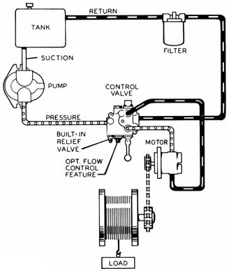
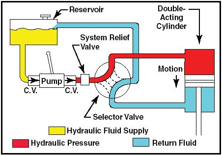
It has previously been noted that "Pascal’s Law" applies to confined liquids. Thus, for liquids to act in a hydraulic fashion, it must function with some type of enclosed system. An enclosed mechanical system that uses liquid hydraulically is known as a hydraulic power pack or a hydraulic power unit. Though specific operating systems are variable, all hydraulic power packs (or units) have the same basic components. These components generally include a reservoir, a pump, a piping/tubing system, valves, and actuators (including both cylinders and motors). Similarly, despite the versatility and adaptability of these mechanisms, these components all work together within similar operating processes, which lie behind all hydraulic power packs.
Hoses or tubes are needed to transport the viscous liquids transmitted from the pump. This piping apparatus then transports the solution to the hydraulic cylinder.
Actuators are hydraulic components which perform the main conversion of hydraulic energy into mechanical energy. Actuators are mainly represented by hydraulic cylinders and hydraulic motors. The main difference between hydraulic cylinders and hydraulic motors lies in the fact that hydraulic cylinders primarily produce linear mechanical motion while hydraulic motors primarily produce rotary mechanical motion.
Hydraulic systems possess various valves to regulate the flow of liquid within a hydraulic system. Directional control valves are used to modify the size and direction of hydraulic fluid flow, while pressure relief valves preempt excessive pressure by limiting the output of the actuators and redirecting fluid back to the reservoir if necessary.
Two main categories of hydraulic pumps to be considered are piston pumps and gear pumps. Within the piston grouping are axial and radial piston pumps. Axial pumps provide linear motion, while radial pumps can operate in a rotary manner. The gear pump category is also divided into two groupings, internal gear pumps and external gear pumps.
No matter piston or gear, each type of hydraulic pump can be either a single-action or double-action pump. Single-action pumps can push, pull or lift in only one direction, while double-action pumps are multidirectional.
The transfer of energy from hydraulic to mechanical is the end goal, with the pump mechanism serving as a generator. In other cases, however, the energy is expelled by means of high pressure streams that help to push, pull and lift heavy loads.
Hydraulic piston pumps and hydraulic clutch pumps, which operate in slightly different ways, are all utilized in heavy machinery for their versatility of motion and directionality.
And hydraulic water pumps are widely used to transfer water. The design of these pumps dictates that, although a small amount of external energy is needed to initiate the action, the weight of the water and its movement can create enough pressure to operate the pump continuously thereafter. Hydraulic ram pumps require virtually no maintenance, as they have only two moving parts. Water from an elevated water source enters one of two chambers through a relatively long, thick pipe, developing inertia as it moves down to the second chamber, which starts the pump.
The initial energy within a hydraulic system is produced in many ways. The simplest form is the hydraulic hand pump which requires a person to manually pressurize the hydraulic fluid. Hydraulic hand pumps are manually operated to pressurize a hydraulic system. Hydraulic hand pumps are often used to calibrate instruments.
Energy-saving pumps that are operated by a compressed air source and require no energy to maintain system pressure. In both the single and two-stage air hydraulic pumps, air pressure is simply converted to hydraulic pressure, and they stall when enough pressure is developed.
Non-positive displacement pumps that are used in hydraulics requiring a large volume of flow. Centrifugal pumps operate at fairly low pressures and are either diffuser or volute types.
Convert hydraulic energy to mechanical power. Hydraulic pumps are specially designed mechanisms used in industrial, commercial and residential settings to create useful energy from the pressurization of various viscous fluids. Hydraulic pumps are extremely simple yet effective mechanisms for moving liquids. "Hydralic" is actually a misspelling of "hydraulic;" hydraulic pumps rely on the power provided by hydraulic cylinders to power various machines and mechanisms.
Pumps in which the clamps and cylinders are quickly extended by high flow at low pressure in the first stage of operation. In the second stage, piston pumps build pressure to a preset level and then maintain that level.
The construction, automotive manufacturing, excavation, agriculture, defense contracting and manufacturing industries are just a few examples of operations that utilize the power of hydraulics in normal, daily processes. Since the use of hydraulics is so widespread, hydraulic pumps are naturally used in a broad array of industries and machines. In all of the contexts which use hydraulic machinery, pumps perform the same basic role of transmitting hydraulic fluid from one place to another to create hydraulic pressure and energy (in conjunction with the actuators).
Various products that use hydraulics include elevators, automotive lifts, automotive brakes, airplane flaps, cranes, shock absorbers, motorboat steering systems, garage jacks, log splitters, etc. Construction sites represent the most common application of hydraulics in large hydraulic machines and various forms of "off-highway" equipment such as diggers, dumpers, excavators, etc. In other environments such as factories and offshore work areas, hydraulic systems are used to power heavy machinery, move heavy equipment, cut and bend material, etc.
While hydraulic power transmission is extremely useful in a wide variety of professional applications, it is generally unwise to depend exclusively on one form of power transmission. On the contrary, combining different forms of power transmission (hydraulic, pneumatic, electrical and mechanical) is the most efficient strategy. Thus, hydraulic systems should be carefully integrated into an overall strategy of power transmission for your specific commercial application. You should invest in finding honest and skilled hydraulic manufacturers / suppliers who can assist you in developing and implementing an overall hydraulic strategy.
When selecting a hydraulic pump, its intended use should be considered when selecting a particular type. This is important since some pumps may carry out only one task, while others allow more flexibility.
The material composition of the pump should also be considered in an application-specific context. The pistons, gears and cylinders are often made of durable materials such as aluminum, steel or stainless steel which can endure the constant wear of repetitive pumping. The materials must hold up not only to the process itself, but to the hydraulic fluids as well. Oils, esters, butanol, polyalkylene glycols and corrosion inhibitors are often included in composite fluids (though simply water is also used in some instances). These fluids vary in terms of viscosity, operating temperature and flash point.
Along with material considerations, manufacturers should compare operating specifications of hydraulic pumps to ensure that intended use does not exceed pump capabilities. Continuous operating pressure, maximum operating pressure, operating speed, horsepower, power source, maximum fluid flow and pump weight are just a few of the many variables in hydraulic pump functionality. Standard measurements such as diameter, length and rod extension should also be compared. As hydraulic pumps are used in motors, cranes, lifts and other heavy machinery, it is integral that they meet operating standards.
It is important to remember that the overall power produced by any hydraulic drive system is affected by various inefficiencies that must be taken into account to get the maximum use out of the system. For example, the presence of air bubbles within a hydraulic drive is notorious for diverting the energy flow within the system (since energy gets wasted en route to the actuators on compressing the bubbles). Using a hydraulic drive system must involve identifying these types of inefficiencies and selecting the best components to mitigate their effects. A hydraulic pump can be considered as the "generator" side of a hydraulic system which begins the hydraulic process (as opposed to the "actuator" side which completes the hydraulic process). Despite their differences, all hydraulic pumps are somehow responsible for displacing fluid volume and bringing it from the reservoir to the actuator(s) via the tubing system. Pumps are generally enabled to do this by some type of internal combustion system.
Even though hydraulic systems are simpler when compared to electrical or mechanical systems, they are still sophisticated systems that should only be handled with care. A fundamental safety precaution when interacting with hydraulic systems is to avoid physical contact if possible. Active fluid pressure within a hydraulic system can pose a hazard even if a hydraulic machine is not actively operating.
Insufficient pumps can lead to mechanical failure in the workplace, which can have serious and costly repercussions. Although pump failure has been unpredictable in the past, new diagnostic technologies continue to improve on detection methods that previously relied upon vibration signals alone. Measuring discharge pressures allows manufacturers to more accurately predict pump wear. Discharge sensors can be easily integrated into existing systems, adding to the safety and versatility of the hydraulic pump.
A container that stores fluid under pressure and is utilized as a source of energy or to absorb hydraulic shock. Accumulator types include piston, bladder and diaphragm.
A circumstance that occurs in pumps when existing space is not filled by available fluid. Cavitation will deteriorate the hydraulic oil and cause erosion of the inlet metal.
Any device used to convert potential energy into kinetic energy within a hydraulic system. Motors and manual energy are both sources of power in hydraulic power units.
A slippery and viscous liquid that is not miscible with water. Oil is often used in conjunction with hydraulic systems because it cannot be compressed.
A device used for converting hydraulic power to mechanical energy. In hydraulic pumps, the piston is responsible for pushing down and pulling up the ram.
A hydraulic mechanism that uses the kinetic energy of a flowing liquid to force a small amount of the liquid to a reservoir contained at a higher level.
A device used to regulate the amount of hydraulic or air flow. In the closed position, there is zero flow, but when the valve is fully open, flow is unrestricted.

High-performance FlowMaster hydraulic pumps combine rotary-driven pump motors with reciprocating pump tubes and flexible control features that perform in desert heat ...
RS PRO hydraulic barrel pumps, designed for use with 40 gallon metal drums, which will pump up to Hypoid 90 viscosity. These hand pumps fearure nitrile rubber (NBR) seals ...
As the new member of the Hydro product range, the hydraulic diaphragm metering pump Hydro/ 2 API 675 (HA2a) meets the requirements of API 675. The pumps stand ...
The radial piston pump type R consists of valve-controlled pump elements arranged in star form around an eccentric. For large flow rates, up to 42 pump elements can be set up in 6 stars ...
... axial piston pump type V60N is designed for open circuits in mobile hydraulics and operate according to the swash plate principle. They are available with the option of a thru-shaft for operating additional ...
... for open circuits in mobile hydraulics and operate according to the swash plate principle. They are available with the option of a thru-shaft for operating additional hydraulic pumps ...
The K3VG series are swash-plate type axial piston pumps which give excellent performance in high flow industrial applications in a compact and cost-effective package.
... Parker’s hydraulic truck pump series F1 featuring high self-priming speed and high efficiency and is one of the leading truck pumps in the market. The F1 pump provide ...
... Piston Pumps provide fixed-displacement power in a unique miniature design. Engineered for open-circuit systems, they bring flexibility to your operation. Compact Piston Pumps ...
... accessibly priced, aluminium gear pumps and motors are among the components most widely utilized in the field of hydraulic applications. Gear pumps are used to operate hydraulic ...
Sophisticated technology in the smallest space - this is what our Alfra electro-hydraulic pumps stand for. Due to the compact design, the powerful drive units also find room when things ...
Our hydraulic cylinder with a quick coupling has a performance up to 11 tons pressure – with a deadweight of only 2,5 kg. The SKP-1 is compatible with the ALFRA foot pump. Your advantage: Your hands are ...
... our ALFRA hydraulic cylinder SKP-1. In a team with the hydraulic pump DSP-120 it is capable to take a variety of challenges – because the SKP-1 working with a maximum operating pressure ...
... quality carbon steel, the pump design features allow it to work with viscous lubricants without any additional complicated priming procedures. The pump, when combined with a suitable ...
The Bansbach hydraulic pump series is an industrial offering that permits a wide range of applications, taking into account its configurable height mechanism. This device allows easy task execution with ...
... alkitronic hydraulic pumps with electric or pneumatic drive provide fast operating speed, reliability, and safety. They are designed for permanent operation. Our hydraulic ...
Bent axis XPi pumps are specially designed to meet the needs of truck equipment. Their compact design allows a direct flange-mounting on the PTO. All models are of 7 piston design to ensure optimal flow ...
Of the same design as the XPi pumps, the XAi fixed displacement pumps are with SAE flange and shaft and are available in displacements from 18 to 63 cc/rev.
With their unique design, PA-PAC pumps offer a robust and durable solution to the high pressure needs of truck applications. Combining the automatic dual direction of rotation, high operating pressure (up to 500 bar peak), ...

In a hydraulic system, fluid is conveyed through the various components by the activity of a pump. Pumps work by converting mechanical energy—e.g., the turning of a gear—into hydraulic (i.e., fluid) energy. Hydraulic pumps may be either fixed displacement (conveys a precise, unchangeable amount of fluid during each rotation) or variable displacement (can be altered to change the amount of fluid conveyed). Of these two types, variable displacement pumps are more complicated in design and, therefore, tend to be more expensive.
Hydraulic pumps are used in a wide range of industrial equipment and, for this reason, they exist in a broad assortment of designs, including the following:
Vane pumps – Vane pumps feature a rotating shaft with a number of thin vanes protruding from it. The vanes effectively separate the housing into distinct compartments, each of which conveys fluid from the input to the output as the central rotor turns. Because the rotor is positioned eccentrically, its motion first steadily increase the volume of space in each compartment as the compartments fill and then decreases them as they empty when the fluid is forcefully expelled through the output.
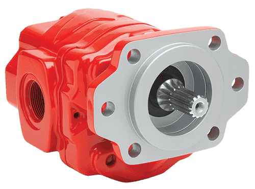
Gear pumps – The typical gear pump has two interlocking gears, one of which is connected to a drive shaft. As the shaft turns, the two gears are put into motion, conveying the hydraulic fluid around the outer perimeter of the housing and finally through the outlet.
Piston pumps – A piston pump is characterised by the presence of one or more pistons, consisting of a cylinder inside a cylinder. The up-and-down motion of the piston conveys hydraulic fluid to the output. These pumps are available in axial and radial designs.
In addition to supplying all types of hydraulic pumps, from stock White House Products can also manufacture piston gear and vane pumps to order. For gear pumps consult the Tailor Made gear pump section of our catalogue. For Vane pumps see the available options in the Vane pump and mtors section of the catalogue. For Piston pumps see the available options in the Standard Piston Pumps section.
If your hydraulic pump requires new parts or to be repaired White House Products can assist with a wide range of spare parts and full repair and test facilities for all types and styles of hydraulic pump. So if you need to replace the entire system, a component or need a component repair, you can count on White House Products for the exact part numbers. Parts for Cessna, Kayaba, Saeur Danfoss, Vickers, and other pump brands are available from stock.
Sometimes, it is a challenge to find an exact match to your application. If a particular hydraulics system manufacturer does not produce a pump for your requirements, we can help. You can have one built to your own specifications, which sets our operation apart from other hydraulic pump suppliers. Register to access this feature, but not before conducting a complete search of our catalogues, as this is the world’s largest selection of hydraulic pumps.
Search filters and the “Quick Find” feature simplify the process of browsing thousands of products from a leading pump system supplier. Your search can be as simple as entering a keyword or part number. By registering, instantly see stock availability and hydraulic pump pricing, and use instant online ordering; for help, our technical support team is always standing by.

A hydraulic system may use one or more motors. Essentially, these motors work by converting hydraulic (fluid) pressure and flow into mechanical power (torque). Hydraulic motors strongly resemble hydraulic pumps in their basic design—in fact, some motors can even be used as pumps if necessary. Hydraulic motors are used in a very broad range of applications, including but not limited to cranes, winches, conveyors, excavators, roll mills, and many others.
As these devices can be found in widely varying applications, hydraulic motors are manufactured in a number of radically different types, each of which with its own unique features.
Gear motors – Hydraulic gear motors utilise an idler gear and a drive gear in a side-by-side configuration. The flow of fluid coming in through the inlet turns the interlocking gears conveying the fluid through the device and into the outlet opening. These inexpensive units are valued for their versatility and dependability.
Piston motors – Hydraulic piston motors are noted for their high power and torque outputs at high and low speeds. These motors are produced in two main varieties. The radial type has multiple pistons around a central shaft, in a design that resembles a star. The axial design is the more common and more compact of the two, with the pistons being housed within a circular cylinder block
Vane motors – These motors contain a series of thin vanes protruding from a rotor to create compartments that carry fluid from the input to the output. Hydraulic vane motors are widely known as quiet, easy-to-service devices.
You can count on a leading hydraulic motor supplier to provide the motors needed for any application. Just as we stock hydraulic pump parts, we offer the parts to build and repair hydraulic motors in the most cost-effective manner. Efficient tools are at your disposal to order quickly and spend little time ordering critical hydraulic components.
White House Products makes it fast and simple to search for hydraulic system parts. Enter a part number or keyword into the Quick Find search tool, or browse the entire catalogue by category, sub-category, and manufacturer. Even search according to OEM or machine type.
When you register on the website, you’ll be able to see prices for hydraulic moors and parts. Product pricing is visible as soon as you log in. Add items to the shopping basket, which stores the details of each item of interest until you purchase it using the secure shopping cart.
If you don’t see a desired hydraulic motor or product online, you can request a hydraulic system supplier catalogue. The catalogue is available in sections that can be viewed online or downloaded to your computer, so product listings can be referenced offline. Our technical support team is always on hand to take your enquiries and help find what you need.
The full inventory of hydraulic motors and other products is available in the United Kingdom (with next-day delivery) and to customers all over the world. Our service is quick, our support team is courteous, and our prices are competitive to match our high standards.

Parker"s Hydraulic Pump and Power Systems Division provides a broad selection of piston pumps, hydraulic motors and power units that help our customers meet their industrial and mobile application needs. Our division is the result of the Parker piston pump business’s acquisition of Denison Hydraulics and merger with the Parker Oildyne Division. Reach higher hydraulic working pressures, get better reliability, higher efficiencies, and achieve lower operating costs and improved productivity on your heavy-duty equipment with Parker’s line of piston pumps and vane pumps, electro-hydraulic actuators, hydraulic motors and power units, piston motors and hydrostatic transmissions.

Hydraulic Power Sales Inc. partners with leading manufacturers to provide hydraulic pumps and motors. Regardless of what you’re looking for, we’re your complete solution—if we don’t have it in stock at our facilities in California, we will find it fast. Our mission is simple: getting you the right part and saving you time and money.
We provide Hydraulic pumps and can be styles such as gear, vane, and piston pumps. Applications can be fixed or variable displacement pumps. With so many styles and brands, it’s important to speak with an expert who can get you the hydraulic pump you need at an affordable price. We offer a wide variety of hydraulic pumps to support your applications and carry trusted brands including:
We provide Hydraulic motors and can be gear and vane, and motors used in simple rotating systems. Other hydraulic motors are gerotor motors, axial piston motors and radial piston motors. We help you select the best motor for your hydraulic applications, enhancing performance for optimal results. We’re proud to carry the following motors from brands you know and trust:
Hydraulic Power Sales Inc. is proud to offer high-quality hydraulic pumps and motors that support a wide range of mobile and industrial applications. Call us today at 916-631-9275 to learn more about our products.

There are typically three types of hydraulic pump constructions found in mobile hydraulic applications. These include gear, piston, and vane; however, there are also clutch pumps, dump pumps, and pumps for refuse vehicles such as dry valve pumps and Muncie Power Products’ Live PakTM.
The hydraulic pump is the component of the hydraulic system that takes mechanical energy and converts it into fluid energy in the form of oil flow. This mechanical energy is taken from what is called the prime mover (a turning force) such as the power take-off or directly from the truck engine.
With each hydraulic pump, the pump will be of either a uni-rotational or bi-rotational design. As its name implies, a uni-rotational pump is designed to operate in one direction of shaft rotation. On the other hand, a bi-rotational pump has the ability to operate in either direction.
For truck-mounted hydraulic systems, the most common design in use is the gear pump. This design is characterized as having fewer moving parts, being easy to service, more tolerant of contamination than other designs and relatively inexpensive. Gear pumps are fixed displacement, also called positive displacement, pumps. This means the same volume of flow is produced with each rotation of the pump’s shaft. Gear pumps are rated in terms of the pump’s maximum pressure rating, cubic inch displacement and maximum input speed limitation.
Generally, gear pumps are used in open center hydraulic systems. Gear pumps trap oil in the areas between the teeth of the pump’s two gears and the body of the pump, transport it around the circumference of the gear cavity and then force it through the outlet port as the gears mesh. Behind the brass alloy thrust plates, or wear plates, a small amount of pressurized oil pushes the plates tightly against the gear ends to improve pump efficiency.
A cylinder block containing pistons that move in and out is housed within a piston pump. It’s the movement of these pistons that draw oil from the supply port and then force it through the outlet. The angle of the swash plate, which the slipper end of the piston rides against, determines the length of the piston’s stroke. While the swash plate remains stationary, the cylinder block, encompassing the pistons, rotates with the pump’s input shaft. The pump displacement is then determined by the total volume of the pump’s cylinders. Fixed and variable displacement designs are both available.
With a fixed displacement piston pump, the swash plate is nonadjustable. Its proportional output flow to input shaft speed is like that of a gear pump and like a gear pump, the fixed displacement piston pump is used within open center hydraulic systems.
As previously mentioned, piston pumps are also used within applications like snow and ice control where it may be desirable to vary system flow without varying engine speed. This is where the variable displacement piston pump comes into play – when the hydraulic flow requirements will vary based on operating conditions. Unlike the fixed displacement design, the swash plate is not fixed and its angle can be adjusted by a pressure signal from the directional valve via a compensator.
Vane pumps were, at one time, commonly used on utility vehicles such as aerial buckets and ladders. Today, the vane pump is not commonly found on these mobile (truck-mounted) hydraulic systems as gear pumps are more widely accepted and available.
Within a vane pump, as the input shaft rotates it causes oil to be picked up between the vanes of the pump which is then transported to the pump’s outlet side. This is similar to how gear pumps work, but there is one set of vanes – versus a pair of gears – on a rotating cartridge in the pump housing. As the area between the vanes decreases on the outlet side and increases on the inlet side of the pump, oil is drawn in through the supply port and expelled through the outlet as the vane cartridge rotates due to the change in area.
Input shaft rotates, causing oil to be picked up between the vanes of the pump which is then transported to pump outlet side as area between vanes decreases on outlet side and increases on inlet side to draw oil through supply port and expel though outlet as vane cartridge rotates
A clutch pump is a small displacement gear pump equipped with a belt-driven, electromagnetic clutch, much like that found on a car’s air conditioner compressor. It is engaged when the operator turns on a switch inside the truck cab. Clutch pumps are frequently used where a transmission power take-off aperture is not provided or is not easily accessible. Common applications include aerial bucket trucks, wreckers and hay spikes. As a general rule clutch pumps cannot be used where pump output flows are in excess of 15 GPM as the engine drive belt is subject to slipping under higher loads.
What separates this pump from the traditional gear pump is its built-in pressure relief assembly and an integral three-position, three-way directional control valve. The dump pump is unsuited for continuous-duty applications because of its narrow, internal paths and the subsequent likelihood of excessive heat generation.
Dump pumps are often direct mounted to the power take-off; however, it is vital that the direct-coupled pumps be rigidly supported with an installer-supplied bracket to the transmission case with the pump’s weight at 70 lbs. With a dump pump, either a two- or three-line installation must be selected (two-line and three-line refer to the number of hoses used to plumb the pump); however, a dump pump can easily be converted from a two- to three-line installation. This is accomplished by inserting an inexpensive sleeve into the pump’s inlet port and uncapping the return port.
Many dump bodies can function adequately with a two-line installation if not left operating too long in neutral. When left operating in neutral for too long however, the most common dump pump failure occurs due to high temperatures. To prevent this failure, a three-line installation can be selected – which also provides additional benefits.
Pumps for refuse equipment include both dry valve and Live Pak pumps. Both conserve fuel while in the OFF mode, but have the ability to provide full flow when work is required. While both have designs based on that of standard gear pumps, the dry valve and Like Pak pumps incorporate additional, special valving.
Primarily used on refuse equipment, dry valve pumps are large displacement, front crankshaft-driven pumps. The dry valve pump encompasses a plunger-type valve in the pump inlet port. This special plunger-type valve restricts flow in the OFF mode and allows full flow in the ON mode. As a result, the horsepower draw is lowered, which saves fuel when the hydraulic system is not in use.
In the closed position, the dry valve allows just enough oil to pass through to maintain lubrication of the pump. This oil is then returned to the reservoir through a bleed valve and small return line. A bleed valve that is fully functioning is critical to the life of this type of pump, as pump failure induced by cavitation will result if the bleed valve becomes clogged by contaminates. Muncie Power Products also offer a butterfly-style dry valve, which eliminates the bleed valve requirement and allows for improved system efficiency.
It’s important to note that with the dry valve, wear plates and shaft seals differ from standard gear pumps. Trying to fit a standard gear pump to a dry valve likely will result in premature pump failure.
Encompasses plunger-type valve in the pump inlet port restricting flow in OFF mode, but allows full flow in ON mode lowering horsepower draw to save fuel when not in use
Wear plates and shaft seals differ from standard gear pumps – trying to fit standard gear pump to dry valve likely will result in premature pump failure
Live Pak pumps are also primarily used on refuse equipment and are engine crankshaft driven; however, the inlet on a Live Pak pump is not outfitted with a shut-off valve. With a Live Pak pump, the outlet incorporates a flow limiting valve. This is called a Live Pak valve. The valve acts as an unloading valve in OFF mode and a flow limiting valve in the ON mode. As a result, the hydraulic system speed is limited to keep within safe operating parameters.
Outlet incorporates flow limiting valve called Live Pak valve – acts as an unloading valve in OFF mode and flow limiting valve in ON mode restricting hydraulic system speed to keep within safe operating parameters
Impeller blades revolve inside the casing, rotating the surround fluids. the blades also lubricate and cool the system. Pump bearings are often made to anti-friction, to help the impeller rotate inside the casing. The pump shaft is made of steel, and its size corresponds to the size of the impeller.
A hydraulic hand pump transforms human power into hydraulic energy by combining pressure and flow. The foundation for hydraulic fluid delivery is the simple notion that a handle gives an internal piston leverage under manual pressure. The piston then pushes the hydraulic fluid into the cylinder port. Water and hydraulic fluid are the two most common fluids, and however other pressure media can also be used.
The hydraulic pressure generated can be used to test, calibrate, and adjust various measuring instruments and tools. Hydraulic hand pumps are widely used to load and test mechanical parts when a user requires precise adjustments. They are also used in lifting and lowering heavy things in material handling equipment, which similarly necessitates precise control over the movement of the objects.
The working medium, requisite pressure range, drive type, etc., are only a few of the functional and hydraulic system requirements that are considered when manufacturing hydraulic pumps. In addition, there are numerous design philosophies and hydraulic pump combinations to choose from. Due to this, only a few pumps can completely fulfill all needs. The most common types of hydraulic pumps have already been described.
The use of hydraulic pumps is still common in industrial settings. Elevators, conveyors, mixers, forklifts, pallet jacks, injection molding machines, presses (shear, stamping, bending, etc.), foundries, steel mills, and slitters are examples of equipment used in material handling. With an application"s need, a hydraulic pump is more likely to be used.
Additionally, hydraulic pumps are used in every conceivable mobile or industrial hydraulic machine. They are used on many different pieces of gear, such as excavators, cranes, loaders, tractors, vacuum trucks, forestry equipment, graders, dump trucks, and mining equipment. Mobile applications use hydraulic pumps more commonly than industrial applications since industrial devices typically don"t use electric actuators.

A gear pump is a type of positive displacement (PD) pump. It moves a fluid by repeatedly enclosing a fixed volume using interlocking cogs or gears, transferring it mechanically using a cyclic pumping action. It delivers a smooth pulse-free flow proportional to the rotational speed of its gears.
Gear pumps use the actions of rotating cogs or gears to transfer fluids. The rotating element develops a liquid seal with the pump casing and creates suction at the pump inlet. Fluid, drawn into the pump, is enclosed within the cavities of its rotating gears and transferred to the discharge. There are two basic designs of gear pump: external and internal(Figure 1).
An external gear pump consists of two identical, interlocking gears supported by separate shafts. Generally, one gear is driven by a motor and this drives the other gear (the idler). In some cases, both shafts may be driven by motors. The shafts are supported by bearings on each side of the casing.
As the gears come out of mesh on the inlet side of the pump, they create an expanded volume. Liquid flows into the cavities and is trapped by the gear teeth as the gears continue to rotate against the pump casing.
No fluid is transferred back through the centre, between the gears, because they are interlocked. Close tolerances between the gears and the casing allow the pump to develop suction at the inlet and prevent fluid from leaking back from the discharge side (although leakage is more likely with low viscosity liquids).
An internal gear pump operates on the same principle but the two interlocking gears are of different sizes with one rotating inside the other. The larger gear (the rotor) is an internal gear i.e. it has the teeth projecting on the inside. Within this is a smaller external gear (the idler –only the rotor is driven) mounted off-centre. This is designed to interlock with the rotor such that the gear teeth engage at one point. A pinion and bushing attached to the pump casing holds the idler in position. A fixed crescent-shaped partition or spacer fills the void created by the off-centre mounting position of the idler and acts as a seal between the inlet and outlet ports.
As the gears come out of mesh on the inlet side of the pump, they create an expanded volume. Liquid flows into the cavities and is trapped by the gear teeth as the gears continue to rotate against the pump casing and partition.
Gear pumps are compact and simple with a limited number of moving parts. They are unable to match the pressure generated by reciprocating pumps or the flow rates of centrifugal pumps but offer higher pressures and throughputs than vane or lobe pumps. Gear pumps are particularly suited for pumping oils and other high viscosity fluids.
Of the two designs, external gear pumps are capable of sustaining higher pressures (up to 3000 psi) and flow rates because of the more rigid shaft support and closer tolerances. Internal gear pumps have better suction capabilities and are suited to high viscosity fluids, although they have a useful operating range from 1cP to over 1,000,000cP. Since output is directly proportional to rotational speed, gear pumps are commonly used for metering and blending operations. Gear pumps can be engineered to handle aggressive liquids. While they are commonly made from cast iron or stainless steel, new alloys and composites allow the pumps to handle corrosive liquids such as sulphuric acid, sodium hypochlorite, ferric chloride and sodium hydroxide.
External gear pumps can also be used in hydraulic power applications, typically in vehicles, lifting machinery and mobile plant equipment. Driving a gear pump in reverse, using oil pumped from elsewhere in a system (normally by a tandem pump in the engine), creates a hydraulic motor. This is particularly useful to provide power in areas where electrical equipment is bulky, costly or inconvenient. Tractors, for example, rely on engine-driven external gear pumps to power their services.
Gear pumps are self-priming and can dry-lift although their priming characteristics improve if the gears are wetted. The gears need to be lubricated by the pumped fluid and should not be run dry for prolonged periods. Some gear pump designs can be run in either direction so the same pump can be used to load and unload a vessel, for example.
The close tolerances between the gears and casing mean that these types of pump are susceptible to wear particularly when used with abrasive fluids or feeds containing entrained solids. However, some designs of gear pumps, particularly internal variants, allow the handling of solids. External gear pumps have four bearings in the pumped medium, and tight tolerances, so are less suited to handling abrasive fluids. Internal gear pumps are more robust having only one bearing (sometimes two) running in the fluid. A gear pump should always have a strainer installed on the suction side to protect it from large, potentially damaging, solids.
Generally, if the pump is expected to handle abrasive solids it is advisable to select a pump with a higher capacity so it can be operated at lower speeds to reduce wear. However, it should be borne in mind that the volumetric efficiency of a gear pump is reduced at lower speeds and flow rates. A gear pump should not be operated too far from its recommended speed.
For high temperature applications, it is important to ensure that the operating temperature range is compatible with the pump specification. Thermal expansion of the casing and gears reduces clearances within a pump and this can also lead to increased wear, and in extreme cases, pump failure.
Despite the best precautions, gear pumps generally succumb to wear of the gears, casing and bearings over time. As clearances increase, there is a gradual reduction in efficiency and increase in flow slip: leakage of the pumped fluid from the discharge back to the suction side. Flow slip is proportional to the cube of the clearance between the cog teeth and casing so, in practice, wear has a small effect until a critical point is reached, from which performance degrades rapidly.
Gear pumps continue to pump against a back pressure and, if subjected to a downstream blockage will continue to pressurise the system until the pump, pipework or other equipment fails. Although most gear pumps are equipped with relief valves for this reason, it is always advisable to fit relief valves elsewhere in the system to protect downstream equipment.
Internal gear pumps, operating at low speed, are generally preferred for shear-sensitive liquids such as foodstuffs, paint and soaps. The higher speeds and lower clearances of external gear designs make them unsuitable for these applications. Internal gear pumps are also preferred when hygiene is important because of their mechanical simplicity and the fact that they are easy to strip down, clean and reassemble.
Gear pumps are commonly used for pumping high viscosity fluids such as oil, paints, resins or foodstuffs. They are preferred in any application where accurate dosing or high pressure output is required. The output of a gear pump is not greatly affected by pressure so they also tend to be preferred in any situation where the supply is irregular.
A gear pump moves a fluid by repeatedly enclosing a fixed volume within interlocking cogs or gears, transferring it mechanically to deliver a smooth pulse-free flow proportional to the rotational speed of its gears. There are two basic types: external and internal. An external gear pump consists of two identical, interlocking gears supported by separate shafts. An internal gear pump has two interlocking gears of different sizes with one rotating inside the other.
Gear pumps are commonly used for pumping high viscosity fluids such as oil, paints, resins or foodstuffs. They are also preferred in applications where accurate dosing or high pressure output is required. External gear pumps are capable of sustaining higher pressures (up to 7500 psi) whereas internal gear pumps have better suction capabilities and are more suited to high viscosity and shear-sensitive fluids.
A hydraulic pump converts mechanical energy into fluid power. It"s used in hydraulic systems to perform work, such as lifting heavy loads in excavators or jacks to being used in hydraulic splitters. This article focuses on how hydraulic pumps operate, different types of hydraulic pumps, and their applications.
A hydraulic pump operates on positive displacement, where a confined fluid is subjected to pressure using a reciprocating or rotary action. The pump"s driving force is supplied by a prime mover, such as an electric motor, internal combustion engine, human labor (Figure 1), or compressed air (Figure 2), which drives the impeller, gear (Figure 3), or vane to create a flow of fluid within the pump"s housing.
A hydraulic pump’s mechanical action creates a vacuum at the pump’s inlet, which allows atmospheric pressure to force fluid into the pump. The drawn in fluid creates a vacuum at the inlet chamber, which allows the fluid to then be forced towards the outlet at a high pressure.
Vane pump:Vanes are pushed outwards by centrifugal force and pushed back into the rotor as they move past the pump inlet and outlet, generating fluid flow and pressure.
Piston pump:A piston is moved back and forth within a cylinder, creating chambers of varying size that draw in and compress fluid, generating fluid flow and pressure.
A hydraulic pump"s performance is determined by the size and shape of the pump"s internal chambers, the speed at which the pump operates, and the power supplied to the pump. Hydraulic pumps use an incompressible fluid, usually petroleum oil or a food-safe alternative, as the working fluid. The fluid must have lubrication properties and be able to operate at high temperatures. The type of fluid used may depend on safety requirements, such as fire resistance or food preparation.
Air hydraulic pump:These pumps have a compact design and do not require an external power source. However, a reliable source of compressed air is necessary and is limited by the supply pressure of compressed air.
Electric hydraulic pump:They have a reliable and efficient power source and can be easily integrated into existing systems. However, these pumps require a constant power source, may be affected by power outages, and require additional electrical safety measures. Also, they have a higher upfront cost than other pump types.
Gas-powered hydraulic pump:Gas-powered pumps are portable hydraulic pumps which are easy to use in outdoor and remote environments. However, they are limited by fuel supply, have higher emissions compared to other hydraulic pumps, and the fuel systems require regular maintenance.
Manual hydraulic pump:They are easy to transport and do not require a power source. However, they are limited by the operator’s physical ability, have a lower flow rate than other hydraulic pump types, and may require extra time to complete tasks.
Hydraulic hand pump:Hydraulic hand pumps are suitable for small-scale, and low-pressure applications and typically cost less than hydraulic foot pumps.
Hydraulic foot pump:Hydraulic foot pumps are suitable for heavy-duty and high-pressure applications and require less effort than hydraulic hand pumps.
Hydraulic pumps can be single-acting or double-acting. Single-acting pumps have a single port that hydraulic fluid enters to extend the pump’s cylinder. Double-acting pumps have two ports, one for extending the cylinder and one for retracting the cylinder.
Single-acting:With single-acting hydraulic pumps, the cylinder extends when hydraulic fluid enters it. The cylinder will retract with a spring, with gravity, or from the load.
Double-acting:With double-acting hydraulic pumps, the cylinder retracts when hydraulic fluid enters the top port. The cylinder goes back to its starting position.
Single-acting:Single-acting hydraulic pumps are suitable for simple applications that only need linear movement in one direction. For example, such as lifting an object or pressing a load.
Double-acting:Double-acting hydraulic pumps are for applications that need precise linear movement in two directions, such as elevators and forklifts.
Pressure:Hydraulic gear pumps and hydraulic vane pumps are suitable for low-pressure applications, and hydraulic piston pumps are suitable for high-pressure applications.
Cost:Gear pumps are the least expensive to purchase and maintain, whereas piston pumps are the most expensive. Vane pumps land somewhere between the other two in cost.
Efficiency:Gear pumps are the least efficient. They typically have 80% efficiency, meaning 10 mechanical horsepower turns into 8 hydraulic horsepower. Vane pumps are more efficient than gear pumps, and piston pumps are the most efficient with up to 95% efficiency.
Automotive industry:In the automotive industry, hydraulic pumps are combined with jacks and engine hoists for lifting vehicles, platforms, heavy loads, and pulling engines.
Process and manufacturing:Heavy-duty hydraulic pumps are used for driving and tapping applications, turning heavy valves, tightening, and expanding applications.
Despite the different pump mechanism types in hydraulic pumps, they are categorized based on size (pressure output) and driving force (manual, air, electric, and fuel-powered). There are several parameters to consider while selecting the right hydraulic pump for an application. The most important parameters are described below:
Speed of operation: If it is a manual hydraulic pump, should it be a single-speed or double-speed? How much volume of fluid per handle stroke? When using a powered hydraulic pump, how much volume per minute? Air, gas, and electric-powered hydraulic pumps are useful for high-volume flows.
Portability: Manual hand hydraulic pumps are usually portable but with lower output, while fuel power has high-output pressure but stationary for remote operations in places without electricity. Electric hydraulic pumps can be both mobile and stationary, as well as air hydraulic pumps. Air hydraulic pumps require compressed air at the operation site.
Operating temperature: The application operating temperature can affect the size of the oil reservoir needed, the type of fluid, and the materials used for the pump components. The oil is the operating fluid but also serves as a cooling liquid in heavy-duty hydraulic pumps.
Operating noise: Consider if the environment has a noise requirement. A hydraulic pump with a fuel engine will generate a higher noise than an electric hydraulic pump of the same size.
Spark-free: Should the hydraulic pump be spark-free due to a possible explosive environment? Remember, most operating fluids are derivatives of petroleum oil, but there are spark-free options.
A hydraulic pump transforms mechanical energy into fluid energy. A relatively low amount of input power can turn into a large amount of output power for lifting heavy loads.
A hydraulic pump works by using mechanical energy to pressurize fluid in a closed system. This pressurized fluid is then used to drive machinery such as excavators, presses, and lifts.
A hydraulic ram pump leverages the energy of falling water to move water to a higher height without the usage of external power. It is made up of a valve, a pressure chamber, and inlet and exit pipes.
A water pump moves water from one area to another, whereas a hydraulic pump"s purpose is to overcome a pressure that is dependent on a load, like a heavy car.
Hydraulic Pumps are any of a class of positive displacement machines used in fluid power applications to provide hydraulic flow to fluid-powered devices such as cylinders, rams, motors, etc. A car’s power-steering pump is one example where an engine-driven rotary-vane pump is common. The engine’s gear-type oil pump is another everyday example. Hydraulic pumps can be motor-driven, too, or manually operated. Variable displacement pumps are especially useful because they can provide infinite adjustment over their speed range with a constant input rpm.
Pumps produce flow. Pressure is resistance to flow. Whereas centrifugal pumps can run against blocked discharges without building up excess pressure, positive-displacement pumps cannot. Hydraulic pumps, like any positive-displacement pump, thus require overpressure protection generally in the form of a pressure-relief valve. Over-pressure relief is often built into the pump itself.
Hydraulic systems are used where compact power is needed and where electrical, mechanical, or pneumatic systems would become too large, too dangerous, or otherwise not up to the task. For construction equipment, hydraulic power provides the means to move heavy booms and buckets. In manufacturing, hydraulic power is used for presses and other high-force applications. At the heart of the hydraulic system is the pump itself and the selection of a correct hydraulic pump hinges on just what the hydraulic system will be expected to do.
Axial piston pumps use axially mounted pistons that reciprocate within internal cylinders to create alternating suction and discharge flow. They can be designed as variable-rate devices making them useful for controlling the speeds of hydraulic motors and cylinders. In this design, a swashplate is used to vary the depth to which each piston extends into its cylinder as the pump rotates, affecting the volume of discharge. A pressure compensator piston is used in some designs to maintain a constant discharge pressure under varying loads.
Radial piston pumps arrange a series of pistons radially around a rotor hub. The rotor, mounted eccentrically in the pump housing, forces the pistons in and out of cylinders as it rotates, which cause hydraulic fluid to be sucked into the cylinder cavity and then be discharged from it. Inlets and outlets for the pump are located in a valve in a central hub. An alternative design places inlets and outlets around the perimeter of the pump housing. Radial piston pumps can be purchased as fixed- or variable-displacement models. In the variable-displacement version, the eccentricity of the rotor in the pump housing is altered to decrease or increase the stroke of the pistons.
Rotary vane pumps use a series of rigid vanes, mounted in an eccentric rotor, which sweep along the inside wall of a housing cavity to create smaller volumes, which forces the fluid out through the discharge port. In some designs, the volume of the fluid leaving the pump can be adjusted by changing the rotational axis of the rotor with respect to the pump housing. Zero flow occurs when the rotor and housing axes coincide.
External Gear pumps rely on the counter-rotating motion of meshed external spur gears to impart motion to a fluid. They are generally fixed-displacement designs, very simple and robust. They are commonly found as close-coupled designs where the motor and pump share a common shaft and mounting. Oil travels around the periphery of the pump housing between the teeth of the gears. On the outlet side, the meshing action of the teeth decreases the volume to discharge the oil. The small amount of oil that is trapped between the re-meshing gears discharges through the bearings and back to the pump’s suction side. External gear pumps are very popular in fixed-displacement hydraulic applications as they are capable of providing very high pressures.
The internal gear pump uses the meshing action of an internal and external gear combined with a crescent-shaped sector element to create fluid flow. The axis of the external gear is offset from that of the internal gear, and as the two gears rotate, their coming out of and into mesh create suction and discharge zones. The sector serves as a barrier between suction and discharge. Another internal gear pump, the gerotor, uses meshing trochoidal gears to achieve the same suction and discharge zones without needing a sector element.
This article presented a brief summary of some of the common types of hydraulic pumps. For more information on additional topics, consult our other guides or visit the Thomas Supplier Discovery Platform to locate potential sources of supply or view details on specific products.

A hydraulic hand pump is a simple, yet essential piece of equipment used in a variety of industries. They are vital for many force applications – especially in construction, manufacturing, and maintenance operations.
However, with so many different models on the market, it can be difficult to know which is best suited to your type of work. This guide will help you understand the different pump types and their features.
Before you go ahead and buy a hydraulic hand pump, it’s important to do your research and understand their differences. With so many to choose from, you will want to compare features and prices. It is also a good idea to assess the quality of the product and if it’s made by a reputable manufacturer.
A hydraulic hand pump does a simple job, which is to deliver pressurized hydraulic flow to a tool and then return it back to the pump reservoir. But that doesn’t mean you should take shortcuts and opt for the first one that appears in your internet search results. There are a few simple but important considerations to take on board that will steer you towards the right product.
When you are choosing a hydraulic hand pump, it is important to prioritize quality over price. A high-quality Enerpac pump will last longer and be more reliable than a cheaper model. You will save money in the long run as you won’t need to replace it for many years.
With each stroke of the handle on a single-speed hydraulic pump, hydraulic oil is drawn from the pump reservoir towards the tool by the same amount. For many applications, this simpler and lower-cost option is fine. But for projects needing greater flow, for example when oil is to be pumped to a large hydraulic cylinder (or multiple cylinders), a single-speed pump can be hard work.
The alternative is a 2 stage hydraulic pump (2 speed), which has the added advantage of delivering high flow at lower working pressures. This gets you faster to the point where the real work begins. I


 8613371530291