
simple hydraulic pump diagram supplier
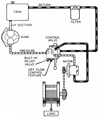
A directional control valve with optional pressure kickout feature controls a double acting cylinder. A pressure gauge is recommended to help spot potential system problems. The tank should be at least one and a half times the pump gpm output and the oil level must remain above the pump intake at all times. (See Logsplitter Safety for more detailed information.)

Hydraulic pumps are mechanisms in hydraulic systems that move hydraulic fluid from point to point initiating the production of hydraulic power. Hydraulic pumps are sometimes incorrectly referred to as “hydrolic” pumps.
They are an important device overall in the hydraulics field, a special kind of power transmission which controls the energy which moving fluids transmit while under pressure and change into mechanical energy. Other kinds of pumps utilized to transmit hydraulic fluids could also be referred to as hydraulic pumps. There is a wide range of contexts in which hydraulic systems are applied, hence they are very important in many commercial, industrial, and consumer utilities.
“Power transmission” alludes to the complete procedure of technologically changing energy into a beneficial form for practical applications. Mechanical power, electrical power, and fluid power are the three major branches that make up the power transmission field. Fluid power covers the usage of moving gas and moving fluids for the transmission of power. Hydraulics are then considered as a sub category of fluid power that focuses on fluid use in opposition to gas use. The other fluid power field is known as pneumatics and it’s focused on the storage and release of energy with compressed gas.
"Pascal"s Law" applies to confined liquids. Thus, in order for liquids to act hydraulically, they must be contained within a system. A hydraulic power pack or hydraulic power unit is a confined mechanical system that utilizes liquid hydraulically. Despite the fact that specific operating systems vary, all hydraulic power units share the same basic components. A reservoir, valves, a piping/tubing system, a pump, and actuators are examples of these components. Similarly, despite their versatility and adaptability, these mechanisms work together in related operating processes at the heart of all hydraulic power packs.
The hydraulic reservoir"s function is to hold a volume of liquid, transfer heat from the system, permit solid pollutants to settle, and aid in releasing moisture and air from the liquid.
Mechanical energy is changed to hydraulic energy by the hydraulic pump. This is accomplished through the movement of liquid, which serves as the transmission medium. All hydraulic pumps operate on the same basic principle of dispensing fluid volume against a resistive load or pressure.
Hydraulic valves are utilized to start, stop, and direct liquid flow in a system. Hydraulic valves are made of spools or poppets and can be actuated hydraulically, pneumatically, manually, electrically, or mechanically.
The end result of Pascal"s law is hydraulic actuators. This is the point at which hydraulic energy is transformed back to mechanical energy. This can be accomplished by using a hydraulic cylinder to transform hydraulic energy into linear movement and work or a hydraulic motor to transform hydraulic energy into rotational motion and work. Hydraulic motors and hydraulic cylinders, like hydraulic pumps, have various subtypes, each meant for specific design use.
The essence of hydraulics can be found in a fundamental physical fact: fluids are incompressible. (As a result, fluids more closely resemble solids than compressible gasses) The incompressible essence of fluid allows it to transfer force and speed very efficiently. This fact is summed up by a variant of "Pascal"s Principle," which states that virtually all pressure enforced on any part of a fluid is transferred to every other part of the fluid. This scientific principle states, in other words, that pressure applied to a fluid transmits equally in all directions.
Furthermore, the force transferred through a fluid has the ability to multiply as it moves. In a slightly more abstract sense, because fluids are incompressible, pressurized fluids should keep a consistent pressure just as they move. Pressure is defined mathematically as a force acting per particular area unit (P = F/A). A simplified version of this equation shows that force is the product of area and pressure (F = P x A). Thus, by varying the size or area of various parts inside a hydraulic system, the force acting inside the pump can be adjusted accordingly (to either greater or lesser). The need for pressure to remain constant is what causes force and area to mirror each other (on the basis of either shrinking or growing). A hydraulic system with a piston five times larger than a second piston can demonstrate this force-area relationship. When a force (e.g., 50lbs) is exerted on the smaller piston, it is multiplied by five (e.g., 250 lbs) and transmitted to the larger piston via the hydraulic system.
Hydraulics is built on fluids’ chemical properties and the physical relationship between pressure, area, and force. Overall, hydraulic applications allow human operators to generate and exert immense mechanical force with little to no physical effort. Within hydraulic systems, both oil and water are used to transmit power. The use of oil, on the other hand, is far more common, owing in part to its extremely incompressible nature.
Pressure relief valves prevent excess pressure by regulating the actuators’ output and redirecting liquid back to the reservoir when necessary. Directional control valves are used to change the size and direction of hydraulic fluid flow.
While hydraulic power transmission is remarkably useful in a wide range of professional applications, relying solely on one type of power transmission is generally unwise. On the contrary, the most efficient strategy is to combine a wide range of power transmissions (pneumatic, hydraulic, mechanical, and electrical). As a result, hydraulic systems must be carefully embedded into an overall power transmission strategy for the specific commercial application. It is necessary to invest in locating trustworthy and skilled hydraulic manufacturers/suppliers who can aid in the development and implementation of an overall hydraulic strategy.
The intended use of a hydraulic pump must be considered when selecting a specific type. This is significant because some pumps may only perform one function, whereas others allow for greater flexibility.
The pump"s material composition must also be considered in the application context. The cylinders, pistons, and gears are frequently made of long-lasting materials like aluminum, stainless steel, or steel that can withstand the continuous wear of repeated pumping. The materials must be able to withstand not only the process but also the hydraulic fluids. Composite fluids frequently contain oils, polyalkylene glycols, esters, butanol, and corrosion inhibitors (though water is used in some instances). The operating temperature, flash point, and viscosity of these fluids differ.
In addition to material, manufacturers must compare hydraulic pump operating specifications to make sure that intended utilization does not exceed pump abilities. The many variables in hydraulic pump functionality include maximum operating pressure, continuous operating pressure, horsepower, operating speed, power source, pump weight, and maximum fluid flow. Standard measurements like length, rod extension, and diameter should be compared as well. Because hydraulic pumps are used in lifts, cranes, motors, and other heavy machinery, they must meet strict operating specifications.
It is critical to recall that the overall power generated by any hydraulic drive system is influenced by various inefficiencies that must be considered in order to get the most out of the system. The presence of air bubbles within a hydraulic drive, for example, is known for changing the direction of the energy flow inside the system (since energy is wasted on the way to the actuators on bubble compression). Using a hydraulic drive system requires identifying shortfalls and selecting the best parts to mitigate their effects. A hydraulic pump is the "generator" side of a hydraulic system that initiates the hydraulic procedure (as opposed to the "actuator" side that completes the hydraulic procedure). Regardless of disparities, all hydraulic pumps are responsible for displacing liquid volume and transporting it to the actuator(s) from the reservoir via the tubing system. Some form of internal combustion system typically powers pumps.
While the operation of hydraulic pumps is normally the same, these mechanisms can be split into basic categories. There are two types of hydraulic pumps to consider: gear pumps and piston pumps. Radial and axial piston pumps are types of piston pumps. Axial pumps produce linear motion, whereas radial pumps can produce rotary motion. The gear pump category is further subdivided into external gear pumps and internal gear pumps.
Each type of hydraulic pump, regardless of piston or gear, is either double-action or single-action. Single-action pumps can only pull, push, or lift in one direction, while double-action pumps can pull, push, or lift in multiple directions.
Vane pumps are positive displacement pumps that maintain a constant flow rate under varying pressures. It is a pump that self-primes. It is referred to as a "vane pump" because the effect of the vane pressurizes the liquid.
This pump has a variable number of vanes mounted onto a rotor that rotates within the cavity. These vanes may be variable in length and tensioned to maintain contact with the wall while the pump draws power. The pump also features a pressure relief valve, which prevents pressure rise inside the pump from damaging it.
Internal gear pumps and external gear pumps are the two main types of hydraulic gear pumps. Pumps with external gears have two spur gears, the spurs of which are all externally arranged. Internal gear pumps also feature two spur gears, and the spurs of both gears are internally arranged, with one gear spinning around inside the other.
Both types of gear pumps deliver a consistent amount of liquid with each spinning of the gears. Hydraulic gear pumps are popular due to their versatility, effectiveness, and fairly simple design. Furthermore, because they are obtainable in a variety of configurations, they can be used in a wide range of consumer, industrial, and commercial product contexts.
Hydraulic ram pumps are cyclic machines that use water power, also referred to as hydropower, to transport water to a higher level than its original source. This hydraulic pump type is powered solely by the momentum of moving or falling water.
Ram pumps are a common type of hydraulic pump, especially among other types of hydraulic water pumps. Hydraulic ram pumps are utilized to move the water in the waste management, agricultural, sewage, plumbing, manufacturing, and engineering industries, though only about ten percent of the water utilized to run the pump gets to the planned end point.
Despite this disadvantage, using hydropower instead of an external energy source to power this kind of pump makes it a prominent choice in developing countries where the availability of the fuel and electricity required to energize motorized pumps is limited. The use of hydropower also reduces energy consumption for industrial factories and plants significantly. Having only two moving parts is another advantage of the hydraulic ram, making installation fairly simple in areas with free falling or flowing water. The water amount and the rate at which it falls have an important effect on the pump"s success. It is critical to keep this in mind when choosing a location for a pump and a water source. Length, size, diameter, minimum and maximum flow rates, and speed of operation are all important factors to consider.
Hydraulic water pumps are machines that move water from one location to another. Because water pumps are used in so many different applications, there are numerous hydraulic water pump variations.
Water pumps are useful in a variety of situations. Hydraulic pumps can be used to direct water where it is needed in industry, where water is often an ingredient in an industrial process or product. Water pumps are essential in supplying water to people in homes, particularly in rural residences that are not linked to a large sewage circuit. Water pumps are required in commercial settings to transport water to the upper floors of high rise buildings. Hydraulic water pumps in all of these situations could be powered by fuel, electricity, or even by hand, as is the situation with hydraulic hand pumps.
Water pumps in developed economies are typically automated and powered by electricity. Alternative pumping tools are frequently used in developing economies where dependable and cost effective sources of electricity and fuel are scarce. Hydraulic ram pumps, for example, can deliver water to remote locations without the use of electricity or fuel. These pumps rely solely on a moving stream of water’s force and a properly configured number of valves, tubes, and compression chambers.
Electric hydraulic pumps are hydraulic liquid transmission machines that use electricity to operate. They are frequently used to transfer hydraulic liquid from a reservoir to an actuator, like a hydraulic cylinder. These actuation mechanisms are an essential component of a wide range of hydraulic machinery.
There are several different types of hydraulic pumps, but the defining feature of each type is the use of pressurized fluids to accomplish a job. The natural characteristics of water, for example, are harnessed in the particular instance of hydraulic water pumps to transport water from one location to another. Hydraulic gear pumps and hydraulic piston pumps work in the same way to help actuate the motion of a piston in a mechanical system.
Despite the fact that there are numerous varieties of each of these pump mechanisms, all of them are powered by electricity. In such instances, an electric current flows through the motor, which turns impellers or other devices inside the pump system to create pressure differences; these differential pressure levels enable fluids to flow through the pump. Pump systems of this type can be utilized to direct hydraulic liquid to industrial machines such as commercial equipment like elevators or excavators.
Hydraulic hand pumps are fluid transmission machines that utilize the mechanical force generated by a manually operated actuator. A manually operated actuator could be a lever, a toggle, a handle, or any of a variety of other parts. Hydraulic hand pumps are utilized for hydraulic fluid distribution, water pumping, and various other applications.
Hydraulic hand pumps may be utilized for a variety of tasks, including hydraulic liquid direction to circuits in helicopters and other aircraft, instrument calibration, and piston actuation in hydraulic cylinders. Hydraulic hand pumps of this type use manual power to put hydraulic fluids under pressure. They can be utilized to test the pressure in a variety of devices such as hoses, pipes, valves, sprinklers, and heat exchangers systems. Hand pumps are extraordinarily simple to use.
Each hydraulic hand pump has a lever or other actuation handle linked to the pump that, when pulled and pushed, causes the hydraulic liquid in the pump"s system to be depressurized or pressurized. This action, in the instance of a hydraulic machine, provides power to the devices to which the pump is attached. The actuation of a water pump causes the liquid to be pulled from its source and transferred to another location. Hydraulic hand pumps will remain relevant as long as hydraulics are used in the commerce industry, owing to their simplicity and easy usage.
12V hydraulic pumps are hydraulic power devices that operate on 12 volts DC supplied by a battery or motor. These are specially designed processes that, like all hydraulic pumps, are applied in commercial, industrial, and consumer places to convert kinetic energy into beneficial mechanical energy through pressurized viscous liquids. This converted energy is put to use in a variety of industries.
Hydraulic pumps are commonly used to pull, push, and lift heavy loads in motorized and vehicle machines. Hydraulic water pumps may also be powered by 12V batteries and are used to move water out of or into the desired location. These electric hydraulic pumps are common since they run on small batteries, allowing for ease of portability. Such portability is sometimes required in waste removal systems and vehiclies. In addition to portable and compact models, options include variable amp hour productions, rechargeable battery pumps, and variable weights.
While non rechargeable alkaline 12V hydraulic pumps are used, rechargeable ones are much more common because they enable a continuous flow. More considerations include minimum discharge flow, maximum discharge pressure, discharge size, and inlet size. As 12V batteries are able to pump up to 150 feet from the ground, it is imperative to choose the right pump for a given use.
Air hydraulic pumps are hydraulic power devices that use compressed air to stimulate a pump mechanism, generating useful energy from a pressurized liquid. These devices are also known as pneumatic hydraulic pumps and are applied in a variety of industries to assist in the lifting of heavy loads and transportation of materials with minimal initial force.
Air pumps, like all hydraulic pumps, begin with the same components. The hydraulic liquids, which are typically oil or water-based composites, require the use of a reservoir. The fluid is moved from the storage tank to the hydraulic cylinder via hoses or tubes connected to this reservoir. The hydraulic cylinder houses a piston system and two valves. A hydraulic fluid intake valve allows hydraulic liquid to enter and then traps it by closing. The discharge valve is the point at which the high pressure fluid stream is released. Air hydraulic pumps have a linked air cylinder in addition to the hydraulic cylinder enclosing one end of the piston.
The protruding end of the piston is acted upon by a compressed air compressor or air in the cylinder. When the air cylinder is empty, a spring system in the hydraulic cylinder pushes the piston out. This makes a vacuum, which sucks fluid from the reservoir into the hydraulic cylinder. When the air compressor is under pressure, it engages the piston and pushes it deeper into the hydraulic cylinder and compresses the liquids. This pumping action is repeated until the hydraulic cylinder pressure is high enough to forcibly push fluid out through the discharge check valve. In some instances, this is connected to a nozzle and hoses, with the important part being the pressurized stream. Other uses apply the energy of this stream to pull, lift, and push heavy loads.
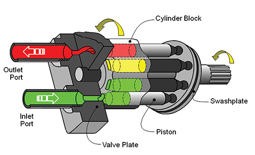
Hydraulic piston pumps transfer hydraulic liquids through a cylinder using plunger-like equipment to successfully raise the pressure for a machine, enabling it to pull, lift, and push heavy loads. This type of hydraulic pump is the power source for heavy-duty machines like excavators, backhoes, loaders, diggers, and cranes. Piston pumps are used in a variety of industries, including automotive, aeronautics, power generation, military, marine, and manufacturing, to mention a few.
Hydraulic piston pumps are common due to their capability to enhance energy usage productivity. A hydraulic hand pump energized by a hand or foot pedal can convert a force of 4.5 pounds into a load-moving force of 100 pounds. Electric hydraulic pumps can attain pressure reaching 4,000 PSI. Because capacities vary so much, the desired usage pump must be carefully considered. Several other factors must also be considered. Standard and custom configurations of operating speeds, task-specific power sources, pump weights, and maximum fluid flows are widely available. Measurements such as rod extension length, diameter, width, and height should also be considered, particularly when a hydraulic piston pump is to be installed in place of a current hydraulic piston pump.
Hydraulic clutch pumps are mechanisms that include a clutch assembly and a pump that enables the user to apply the necessary pressure to disengage or engage the clutch mechanism. Hydraulic clutches are crafted to either link two shafts and lock them together to rotate at the same speed or detach the shafts and allow them to rotate at different speeds as needed to decelerate or shift gears.
Hydraulic pumps change hydraulic energy to mechanical energy. Hydraulic pumps are particularly designed machines utilized in commercial, industrial, and residential areas to generate useful energy from different viscous liquids pressurization. Hydraulic pumps are exceptionally simple yet effective machines for moving fluids. "Hydraulic" is actually often misspelled as "Hydralic". Hydraulic pumps depend on the energy provided by hydraulic cylinders to power different machines and mechanisms.
There are several different types of hydraulic pumps, and all hydraulic pumps can be split into two primary categories. The first category includes hydraulic pumps that function without the assistance of auxiliary power sources such as electric motors and gas. These hydraulic pump types can use the kinetic energy of a fluid to transfer it from one location to another. These pumps are commonly called ram pumps. Hydraulic hand pumps are never regarded as ram pumps, despite the fact that their operating principles are similar.
The construction, excavation, automotive manufacturing, agriculture, manufacturing, and defense contracting industries are just a few examples of operations that apply hydraulics power in normal, daily procedures. Since hydraulics usage is so prevalent, hydraulic pumps are unsurprisingly used in a wide range of machines and industries. Pumps serve the same basic function in all contexts where hydraulic machinery is used: they transport hydraulic fluid from one location to another in order to generate hydraulic energy and pressure (together with the actuators).
Elevators, automotive brakes, automotive lifts, cranes, airplane flaps, shock absorbers, log splitters, motorboat steering systems, garage jacks and other products use hydraulic pumps. The most common application of hydraulic pumps in construction sites is in big hydraulic machines and different types of "off-highway" equipment such as excavators, dumpers, diggers, and so on. Hydraulic systems are used in other settings, such as offshore work areas and factories, to power heavy machinery, cut and bend material, move heavy equipment, and so on.
Fluid’s incompressible nature in hydraulic systems allows an operator to make and apply mechanical power in an effective and efficient way. Practically all force created in a hydraulic system is applied to the intended target.
Because of the relationship between area, pressure, and force (F = P x A), modifying the force of a hydraulic system is as simple as changing the size of its components.
Hydraulic systems can transfer energy on an equal level with many mechanical and electrical systems while being significantly simpler in general. A hydraulic system, for example, can easily generate linear motion. On the contrary, most electrical and mechanical power systems need an intermediate mechanical step to convert rotational motion to linear motion.
Hydraulic systems are typically smaller than their mechanical and electrical counterparts while producing equivalents amounts of power, providing the benefit of saving physical space.
Hydraulic systems can be used in a wide range of physical settings due to their basic design (a pump attached to actuators via some kind of piping system). Hydraulic systems could also be utilized in environments where electrical systems would be impractical (for example underwater).
By removing electrical safety hazards, using hydraulic systems instead of electrical power transmission improves relative safety (for example explosions, electric shock).
The amount of power that hydraulic pumps can generate is a significant, distinct advantage. In certain cases, a hydraulic pump could generate ten times the power of an electrical counterpart. Some hydraulic pumps (for example, piston pumps) cost more than the ordinary hydraulic component. These drawbacks, however, can be mitigated by the pump"s power and efficiency. Despite their relatively high cost, piston pumps are treasured for their strength and capability to transmit very viscous fluids.
Handling hydraulic liquids is messy, and repairing leaks in a hydraulic pump can be difficult. Hydraulic liquid that leaks in hot areas may catch fire. Hydraulic lines that burst may cause serious injuries. Hydraulic liquids are corrosive as well, though some are less so than others. Hydraulic systems need frequent and intense maintenance. Parts with a high factor of precision are frequently required in systems. If the power is very high and the pipeline cannot handle the power transferred by the liquid, the high pressure received by the liquid may also cause work accidents.
Even though hydraulic systems are less complex than electrical or mechanical systems, they are still complex systems that should be handled with caution. Avoiding physical contact with hydraulic systems is an essential safety precaution when engaging with them. Even when a hydraulic machine is not in use, active liquid pressure within the system can be a hazard.
Inadequate pumps can cause mechanical failure in the place of work that can have serious and costly consequences. Although pump failure has historically been unpredictable, new diagnostic technology continues to improve on detecting methods that previously relied solely on vibration signals. Measuring discharge pressures enables manufacturers to forecast pump wear more accurately. Discharge sensors are simple to integrate into existing systems, increasing the hydraulic pump"s safety and versatility.
Hydraulic pumps are devices in hydraulic systems that move hydraulic fluid from point to point, initiating hydraulic power production. They are an important device overall in the hydraulics field, a special kind of power transmission that controls the energy which moving fluids transmit while under pressure and change into mechanical energy. Hydraulic pumps are divided into two categories namely gear pumps and piston pumps. Radial and axial piston pumps are types of piston pumps. Axial pumps produce linear motion, whereas radial pumps can produce rotary motion. The construction, excavation, automotive manufacturing, agriculture, manufacturing, and defense contracting industries are just a few examples of operations that apply hydraulics power in normal, daily procedures.
This page provides the chapter on basic fluid power diagrams and fluid power systems from the U.S. Navy"s fluid power training course, NAVEDTRA 14105A, "Fluid Power," Naval Education and Training Professional Development and Technology Center, July 2015.
In the preceding chapters, you learned about hydraulic and pneumatic fluids and components of fluid power systems. While having knowledge of system components is essential, it is difficult to understand the interrelationships of these components by simply watching the system operate. The knowledge of system interrelation is required to effectively troubleshoot and maintain a fluid power system. Diagrams provided in applicable technical publications or drawings are a valuable aid in understanding the operation of the system and in diagnosing the causes of malfunctions.
This chapter explains the different types of diagrams used to illustrate fluid power circuits, including some of the symbols that depict fluid power components. Included in this chapter are descriptions and illustrations denoting the differences between open-center and closed-center fluid power systems. The last part of the chapter describes and illustrates some applications of basic fluid power systems.
As mentioned in this chapter"s introduction, to troubleshoot fluid power systems intelligently, a mechanic or technician must be familiar with the system on which he or she is working. The mechanic must know the function of each component in the system and have a mental picture of its location in relation to other components. The mental picture can be attained by studying the diagrams of the system.
A diagram may be defined as a graphic representation of an assembly or system that indicates the various parts and expresses the methods or principles of operations. The ability to read diagrams is a basic requirement for understanding the operation of fluid power systems. Understanding the diagrams of a system requires having knowledge of the symbols used in the schematic diagrams.
The American Society for Testing and Materials (ASTM) Standard F1000-13 lists mechanical symbols used on piping prints other than those for aeronautical, aerospacecraft, and spacecraft. Many of these symbols are also listed in the Organizational, Intermediate and Depot Maintenance Aviation Hydraulics Manual, Naval Air Systems Command (NAVAIR) 01-1A-17. A few of the common plumbing and piping symbols from the ASTM Standard F1000-13 and the Symbols, Piping Systems, Naval Sea Systems Command (NAVSEA) Standard Drawing 803-5001049 are illustrated in Figure 12-1.
Each symbol is drawn to show the normal or neutral condition of each component unless multiple circuit diagrams are furnished showing various phases of circuit operation
Pictorial diagrams (Figure 12-2) show the general location and actual appearance of each component, all interconnecting piping, and the general piping arrangement. This type of diagram is sometimes referred to as an installation diagram. Diagrams of this type are invaluable to maintenance personnel in identifying and locating components of a system.
Cutaway diagrams (Figure 12-3) show the internal working parts of all fluid power components in a system. The diagrams include controls and actuating mechanisms and all interconnecting piping. Cutaway diagrams do not normally use symbols.
The primary purpose of a graphic (schematic) diagram is to enable the maintenance person to trace the flow of fluid from component to component within the system. This type of diagram uses standard symbols to show each component and includes all interconnecting piping. Additionally, the diagram contains a component list, pipe size, data on the sequence of operation, and other pertinent information. The graphic diagram (Figure 12-4) does not indicate the physical location of the various components, but it does show the relationship of each component to the other components within the system.
One type of system that is sometimes used in hydraulically operated equipment is the open-center system. An open-center system is one having fluid flow, but no pressure in the system when the actuating mechanisms are idle.
Another fluid power system used in hydraulically operated equipment is the closed-center system. In a closed-center system, the fluid in the system remains pressurized from the pump (or regulator) to the directional control valve while the pump is operating. In this type of system, any number of subsystems may be incorporated, with a separate directional control valve for each subsystem. The directional control valves are arranged in parallel so that system pressure acts equally on all control valves.
In an open-center system, the pump circulates the fluid from the reservoir, through the selector valves, and back to the reservoir (Figure 12-5, view A). The open-center system may employ any number of subsystems, with a selector valve for each subsystem. Unlike the closed-center system, the selector valves of the open-center system are always connected in series with each other. In this arrangement, the system pressure line goes through each selector valve. Fluid is always allowed free passage through each selector valve and back to the reservoir until one of the selector valves is positioned to operate a mechanism.
When one of the selector valves is positioned to operate an actuating device, fluid is directed from the pump through one of the working lines to the actuator (Figure 12-5, view B). With the selector valve in this position, the flow of fluid through the valve to the reservoir is blocked. The pressure builds up in the system to overcome the resistance and moves the piston of the actuating cylinder. The fluid from the opposite end of the actuator returns to the selector valve and flows back to the reservoir. Operation of the system following actuation of the component depends on the type of selector valve being used.
Several types of selector valves are used in conjunction with the open-center system. One type is both manually engaged and manually disengaged. First, the valve is manually moved to an operating position. Then, the actuating mechanism reaches the end of its operating cycle, and the pump output continues until the system relief valve relieves the pressure. The relief valve unseats and allows the fluid to flow back to the reservoir. The system pressure remains at the relief valve set pressure until the selector valve is manually returned to the neutral position. This action reopens the open-center flow and allows the system pressure to drop to line resistance pressure. The manually engaged and pressure disengaged type of selector valve is similar to the valve previously discussed. When the actuating mechanism reaches the end of its cycle, the pressure continues to rise to a predetermined pressure. The valve automatically returns to the neutral position and to open-center flow.
In the closed-center system, the fluid is under pressure whenever the power pump is operating. Figure 12-6 shows a complex closed-center system. The power pump may be one used with a separate pressure regulator control. The power pump may also be used with an integral pressure control valve that eliminates the need for a pressure regulator. This system differs from the open-center system in that the selector or directional control valves are arranged in parallel and not in series. The means of controlling pump pressure will vary in the closed-center system. If a constant delivery pump is used, the system pressure will be regulated by a pressure regulator. A relief valve acts as a backup safety device in case the regulator fails. If a variable displacement pump is used, system pressure is controlled by the pump"s integral pressure mechanism compensator. The compensator automatically varies the volume output. When pressure approaches normal system pressure, the compensator begins to reduce the flow output of the pump. The pump is fully compensated (near zero flow) when normal system pressure is attained. When the pump is in this fully compensated condition, its internal bypass mechanism provides fluid circulation through the pump for cooling and lubrication. A relief valve is installed in the system as a safety backup.
The hydraulic power drive has been used in the Navy for many years. Proof of its effectiveness is that it has been used to train and elevate nearly all caliber guns, from the 40 mm gun mount to the 16-inch turret. In addition to gun mounts and turrets, hydraulic power drives are used to position rocket launchers and missile launchers, and to drive and control such equipment as windlasses, capstans, and winches.
Hydraulic power drives differ in some respects, such as size, method of control, and so forth. However, the fundamental operating principles are similar. The following paragraphs discuss the fundamental operating principles of a hydraulic power drive that is representative of those used to operate the 5-inch/54-caliber gun mount.
Figure 12-7 shows the basic components of the train power drive. The electric motor is constructed with drive shafts at both ends. The forward shaft drives the A-end pump through reduction gears, and the after shaft drives the auxiliary pumps through the auxiliary reduction gears. The reduction gears are installed because the pumps are designed to operate at a speed much slower than that of the motor.
The replenishing pump is a spur gear pump. Its purpose is to replenish fluid to the active system of the power drive. It receives its supply of fluid from the reservoir and discharges it to the B-end valve plate. This discharge of fluid from the pump is held at a constant pressure by the action of a pressure relief valve. (Because the capacity of the pump exceeds replenishing demands, the relief valve is continuously allowing some of the fluid to flow back to the reservoir.)
The sump pump and oscillator unit has a twofold purpose. It pumps leakage, which collects in the sump of the indicator regulator, to the expansion tank. Additionally, it transmits a pulsating effect to the fluid in the response pressure system. Oscillations in the hydraulic response system help eliminate static friction of valves, allowing hydraulic control to respond faster.
The control pressure pump supplies high-pressure fluid for the hydraulic control system, brake pistons, lock piston, and the hand-controlled clutch operating piston. The control pressure pump is a fixed-displacement, axial piston type. An adjustable relief valve is used to limit the operating pressure at the outlet of the pump.
For the purpose of this text, control constitutes the relationship between the stroke control shaft and the tilting box. The stroke control shaft is one of the piston rods of a double-acting piston-type actuating cylinder. This actuating cylinder and its direct means of control are referred to as the main cylinder assembly (Figure 12-8). It is the link between the hydraulic followup system and the power drive itself.
Figure 12-9 is a simplified block diagram showing the main element of the hydraulic power drive system under automatic control for clockwise and counterclockwise rotation.
The indicator regulator receives an initial electrical gun-order from the director-computer, compares it to the existing mount position, and sends an error signal to the hydraulic control mechanism in the regulator. The hydraulic control mechanism controls the flow to the stroke control shaft, which positions the tilting box in the A-end of the transmission. Its tilt controls the volume and direction of fluid pumped to the B-end and, therefore, the speed and direction of the drive shaft of the B-end. Through mechanical linkage, the B-end output shaft moves the gun in the direction determined by the signal. At the same time, B-end response is transmitted to the indicator regulator and is continuously combined with incoming gun-order signals to give the error between the two. This error is modified hydraulically, according to the system of mechanical linkages and valves in the regulator. When the gun is lagging behind the signal, its movement is accelerated; and when it begins to catch up, its movement is slowed down so that it will not overrun excessively.
If the landing gear fails to extend to the down and locked position, each naval aircraft has an emergency method to extend the landing gear. Emergency extension systems may vary from one aircraft to another. The methods used may be the auxiliary/emergency hydraulic system, the air or nitrogen system, or the mechanical free-fall system. An aircraft may contain a combination of these systems. For example, the main landing gear and the nose gear emergency extension may be operated by the auxiliary/hydraulic system method.
Pneumatic pressure actuates the dump valves to the emergency position. The valves are held in position by a spring-loaded detent. In this position, the uplines between the dump valves and the respective selector valves are blocked off. All landing gear and tail skid system uplines are ported to the combined system reservoir through the respective dump valves. (With the selector valves bypassed, a malfunction in either selector valve cannot prevent emergency extension.) Hydraulic fluid on the up side of each actuating cylinder flows back to the reservoir and allows pneumatic pressure to enter the down side and extend the gear and the tail skid.
Pneumatic pressure applied to each shuttle valve shifts a spool over to block off the hydraulic port. Pressure enters the down port and extends the actuating cylinder, displacing hydraulic fluid on the up side back to the reservoir through the landing gear or tail skid dump valve. (The main gear doors and the main gear shock struts begin to lower at the same time since the hydraulic door timer check valves are bypassed during pneumatic operation; however, the doors open fast enough to clear the shock struts since the door cylinders have approximately one-half the stroke of the gear actuating cylinders.)
Jet blast deflectors (JBDs) onboard aircraft carriers are raised and lowered by hydraulic cylinders through mechanical linkage. Two hydraulic cylinders are attached to each JBD panel shaft by crank assemblies (Figure 12-11). The shaft is rotated by the push and pull operation of the hydraulic cylinders. Shaft rotation extends or retracts the linkage to raise or lower the JBD panels. This operation is designed so that in the event of a failure of one of the hydraulic cylinders, the other one will raise or lower the panels.
Hydraulic fluid from the catapult hydraulic supply system is supplied to the JBD hydraulic system through an isolation valve and a filter to the four-way control valve (stack valve) assembly (Figure 12-12).
All three valves are secured together to conserve space and simplify connection to a subplate or manifold as shown in Figure 12-12. One stack valve controls fluid flow for a pair of panel assemblies. Three stack valves are required for Mk 7 Mod 0/2 and two stack valves for Mk 7 Mod 1 JBDs. Hydraulic fluid at 2,500 psi from the associated catapult is supplied to the stack valve, with all fluid return lines going to that catapult gravity tank.
With hydraulic fluid at normal operating pressure and neither solenoid B (raise) nor solenoid A (lower) energized, fluid flows through the sequence valve and pilot valve to both sides of the slide in the main valve. This pressure to both sides of the slide keeps it centered and blocks fluid flow into and out of both ends of the hydraulic cylinders.
When a raise switch is actuated (Figure 12-13), solenoid B in the pilot valve energizes, shifting the spool and directing pressure to a pilot port at the main valve slide. The slide shifts and directs fluid to port A of both hydraulic cylinders. The hydraulic cylinder pistons extend, pushing the crank assembly of the operating gear aft and rotating the shaft. Rotation of the shaft extends the operating gear linkage and raises the associated panel assemblies. During the raise cycle, fluid in the cylinder lower port B vents to the gravity tank through the main valve. If the raise switch is released during the raise cycle, solenoid B de-energizes, a spring returns the solenoid spool to the centered position, and panel movement will stop.
When a lower switch is actuated (Figure 12-14), solenoid A in the pilot valve energizes, shifting the spool and directing pressure to a pilot port at the main valve slide. The slide shifts in the opposite direction (from rising) and directs fluid to port B of both hydraulic cylinders. The pistons retract, pulling the crank assembly of the operating gear forward and rotating the shaft. The rotation of the shaft retracts the operating gear linkage and lowers the panels. During the lower cycle, fluid in the raise port A vents to the gravity tank through the main valve. If the lower switch is released during the lower cycle, solenoid A de-energizes, a spring returns the solenoid spool to the centered position, and panel movement will stop.
PDH Classroom offers a continuing education course based on this basic diagrams and systems reference page. This course can be used to fulfill PDH credit requirements for maintaining your PE license.
Below are some common illustrations of equipment located on fluids circuit diagrams, followed by descriptions of the most common elements. Later in this article series we will describe some simple hydraulic and pneumatic circuits composed of these circuit elements.
Hydraulic pumps are used to pump oil from the power unit to other parts of the hydraulic system. Some pumps have control options such as pressure or flow compensators.
Heat exchangers are used to remove heat from the circulating oil in the hydraulic system. The most common heat exchanger is water-to-oil but some times air-to-oil units are used. Coolers will cool the fluid.
Proportional valves are electrically controlled hydraulic valves. These valves proportionally control the hydraulic pressure and/or flow based on an electrical input signal.
For more information about reading hydraulic and pneumatic circuit diagrams, read the next article in this series which describes sample hydraulic circuits, or contact your Valmet representative.

This ability to control either the flow or pressure is possible through two different system designs – an open center or closed center systems. The terms open center and closed center are used to differentiate the two system designs as each describes the construction of the directional control valve as well as the type of hydraulic circuit being used within the system. With an open center system, flow is continuous and pressure is intermittent – which is contrary to a closed center system where the flow is intermittent and the pressure continuous.
Within an open center system, as the pump turns flow is generated and then directed back to the tank through a central passage within the directional control valve. When one of the directional control valve’s spools is stroked, the flow is focused toward a load and pressure is created. Once the pressure exceeds the load, the load moves and the hydraulic work is executed.
Flow within a closed center system is also created with the turning of the pump; however, only enough flow is being produced to keep the pump lubricated and to achieve a standby pressure at the directional control valve. In a closed center system, when a spool is stroked a passage is exposed for the flow to enter while a pressure signal is sent from the directional control valve to the pump. This pressure signal informs the pump to then produce the flow needed to complete the hydraulic work.
Traditionally, an open center system is less expensive due to the fixed displacement pump used, which costs less than the variable displacement pump often used for a closed center system. A closed center system, while more expensive perhaps, is usually more efficient as it is not continuously sending oil through the valve when it is not being used. Consequently, less energy and less fuel is used – which results in savings on fuel costs.
Open center systems can be converted to closed center systems and vice versa; although, often times the system is designed as open center or closed center from the get-go. A conversion is not usually done on a current system, specifically an open to close center, as converting an open center directional control valve to a closed center directional control valve requires additional items so that the pump can dump excess flow when not needed.
In order for the pump to dump excess flow, it will require a full-flow dump valve or something similar for when the sectional valve doesn’t need oil. Typically, an electric dump valve is used in conjunction with electrically operated work sections to allow the valve and pump to communicate when flow is not needed; otherwise, the pump will always be sending a larger volume of oil regardless of whether there is work that needs completed.
A fixed displacement pump can be used within a closed center system; however, those building the system will need to have the appropriate knowledge to set up the system correctly with the necessary items. Converting a closed center system to an open center system, on the other hand, requires making an adjustment to the outlet and opening up the internal passage ways within the valve allowing the oil to flow freely through the valve straight to tank. However, not all valves have the option built in to convert between open and closed centers via the outlet.
When specifying a hydraulic system, the type of system design should ultimately be determined based on the application or system requirements. But in order to fully understand whether an open or closed center system is needed – knowing the differences between designs, the hydraulic work requirements and the importance of cost versus efficiency will be the first step.
A hydraulic system is one of the drive systems which are being used for the control of machinery and equipment. The other two commonly employed drive systems are based on pneumatics and electric power. The word ‘hydraulics’ came from the Greek word ‘hydraulikos’ which means water organ which in turn means water and pipe. It was in early 1900s when the first practical application of hydraulics was done. The hydraulic systems originated from ‘water hydraulics’ which was being practiced since a hundred year before the fluid power systems emerged.
Hydraulics is a branch of science and engineering concerned with the use of fluids to perform mechanical tasks. It is part of the more general discipline of fluid power. Typically, the fluid used in a hydraulic system is an incompressible liquid such as mineral based hydraulic oil. Pressure is applied by a piston to fluid in a cylinder, causing the fluid to press on another piston which delivers energy to a load. If the areas of the two pistons are different, then the force applied to the first piston is different from the force exerted by the second piston. This creates a mechanical advantage.
A controlled application of force is a common requirement for a production process. These operations in a production process are performed mainly by using a prime mover. The prime mover can provide various movements to the objects by using some mechanical attachment. The enclosed fluids (liquids and gases) can also be used as prime movers to provide controlled motion and force to the objects or substances. The specially designed enclosed fluid systems can provide both linear as well as rotary motion. The high magnitude controlled force can also be applied by using these systems. This kind of enclosed fluid based systems using pressurized incompressible liquids as transmission media are called as hydraulic systems. The hydraulic system works on the principle of Pascal’s law which says that the pressure in an enclosed fluid is uniform in all the directions. The force given by fluid is given by the multiplication of pressure and area of cross section (Fig 1). As the pressure is same in all the direction, the smaller piston feels a smaller force and a large piston feels a large force. Hence, a large force can be generated with smaller force input by using hydraulic systems.
Hydraulic oil also known as hydraulic fluid is the medium by which power is transferred in the equipments of the hydraulic system. It has the main purpose of transferring potential or kinetic energy (pressure and movements), create volume flow between pump and the motor, and reduce the wear of parts which rub against each other. In addition, it protects the system from corrosion and helps carry away the heat produced during energy the transformation. Important properties of the hydraulic oil include (i) viscosity, (ii) viscosity index, (iii) shear stability, (iv) pour point, (v) sealing compatibility, (vi) density, (vii) foaming characteristic, (viii) bulk modulus / compressibility, (ix) cleanliness, and (x) water content. Free air in the hydraulic oil is considered as contamination. Air typically enters the circuit through the suction line if the seals and fittings are not tight. This free air then can be dissolved in the hydraulic oil. Air release is a measure and there is a time needed to release air bubbles (free air) contained in the oil to the surfaces.
The schematics of a hydraulic system along with a simple hydraulic system are shown in Fig 2. As shown in the schematics of a hydraulic system, the output shaft transfers the motion or force while all other parts help to control the system. The storage / fluid tank is a reservoir for the hydraulic fluid which is used as a transmission media. The fluid used is generally high density incompressible oil. It is filtered to remove dust or any other unwanted particles and then pumped by the hydraulic pump. The capacity of pump depends on the hydraulic system design. The pump normally delivers constant volume in each revolution of the pump shaft. Hence, the fluid pressure can increase indefinitely at the dead end of the piston until the system fails. The pressure regulator is used to avoid such situations which redirect the excess fluid back to the storage tank. The movement of piston is controlled by changing liquid flow from port A and port B. The cylinder movement is controlled by using control valve which directs the fluid flow. The fluid pressure line is connected to the port B to raise the piston and it is connected to port A to lower down the piston. The valve can also stop the fluid flow in any of the port. The leak proof piping is important from the aspects of safety, environmental hazards, and economy. Some accessories such as flow control system, travel limit control, electric motor starter, and overload protection etc. are also used in the hydraulic systems.
There are two types of hydraulic systems namely (i) open centre system, and (ii) closed centre system. An open centre system is one which has fluid flow, but no pressure in the system when the actuating mechanisms are idle. The pump circulates the fluid from the reservoir, through the selector valves, and back to the reservoir. The open centre system can employ any number of subsystems, with a selector valve for each subsystem. The selector valves of the open centre system are always connected in series with each other. In this arrangement, the system pressure line goes through each selector valve. Fluid is always allowed free passage through each selector valve and back to the reservoir until one of the selector valves is positioned to operate a mechanism. When one of the selector valves is positioned to operate an actuating device, fluid is directed from the pump through one of the working lines to the actuator. With the selector valve in this position, the flow of fluid through the valve to the reservoir is blocked. The pressure builds up in the system to overcome the resistance and moves the piston of the actuating cylinder and the fluid from the opposite end of the actuator returns to the selector valve and flows back to the reservoir. Operation of the system following actuation of the component depends on the type of selector valve being used.
In the closed centre system, the fluid is under pressure whenever the power pump is operating. There are a number of actuators arranged in parallel out of which some of the actuating units are operating at the same time, while some other actuating units are not operating. This system differs from the open centre system in that the selector or directional control valves are arranged in parallel and not in series. The means of controlling pump pressure varies in the closed centre system. If a constant delivery pump is used, the system pressure is regulated by a pressure regulator. A relief valve acts as a backup safety device in case the regulator fails. If a variable displacement pump is used, system pressure is controlled by the integral pressure mechanism compensator of the pump. The compensator automatically varies the volume output. When pressure approaches normal system pressure, the compensator begins to reduce the flow output of the pump. The pump is fully compensated (near zero flow) when normal system pressure is attained. When the pump is in this fully compensated condition, its internal bypass mechanism provides fluid circulation through the pump for cooling and lubrication. A relief valve is installed in the system as a safety backup.
A hydraulic system consists of a number of parts for its proper functioning. Regardless of its function and design, a hydraulic system has a minimum number of basic components. The main components of a hydraulic system are (i) hydraulic pump, (ii) reservoir for hydraulic fluid, (iii) filter, (iv) actuator, (v) accumulator, (vi) directional control valve, (vii) flow control valve, (viii) pressure relief valve, and (ix) pipes and fittings.
Hydraulic pump – Hydraulic pump converts mechanical energy from a prime mover (electric motor) into hydraulic (pressure) energy. The pressure energy is used then to operate an actuator. Pump pushes on a hydraulic fluid and create flow. The combined pumping and driving motor unit is known as hydraulic pump. The hydraulic pump takes hydraulic fluid from the reservoir and delivers it to the rest of the hydraulic circuit. In general, the speed of the pump is constant and the pump delivers an equal volume of fluid in each revolution. The amount and direction of fluid flow is controlled by some external mechanisms. In some cases, the hydraulic pump itself is operated by a servo controlled motor but it makes the system complex. The hydraulic pump is characterized by its flow rate capacity, power consumption, drive speed, pressure delivered at the outlet, and efficiency of the pump. The pump is normally not 100 % efficient. The efficiency of a pump can be specified by two ways. One is the volumetric efficiency which is the ratio of actual volume of fluid delivered to the maximum theoretical volume possible. Second is power efficiency which is the ratio of output hydraulic power to the input mechanical / electrical power. The typical efficiency of a hydraulic pump varies from 90 % to 98 %. The hydraulic pumps are generally of two types, namely (i) centrifugal pump, and (ii) reciprocating pump.
Centrifugal pump uses rotational kinetic energy to deliver the fluid. The rotational energy generally comes from an electric motor. The fluid enters the pump impeller along or near to the rotating axis, accelerates in the propeller and flung out to the periphery by centrifugal force. In centrifugal pump the delivery is not constant and varies according to the outlet pressure. These pumps are not suitable for high pressure applications and are generally used for low-pressure and high-volume flow applications. Most of the centrifugal pumps are not self-priming and the pump casing needs to be filled with liquid before the pump is started.
The reciprocating pump is a positive plunger pump. It is also known as positive displacement pump or piston pump. It is frequently used where relatively small quantity is to be handled and the delivery pressure is quite large. The construction of these pumps is similar to the four stroke engine. The crank is driven by some external rotating motor. The piston of the pump reciprocates due to crank rotation. The piston moves down in one half of crank rotation, the inlet valve opens and fluid enters into the cylinder. In second half crank rotation the piston moves up, the outlet valve opens and the fluid moves out from the outlet. At a time, only one valve is opened and another is closed so there is no fluid leakage. Depending on the area of cylinder the pump delivers constant volume of fluid in each cycle independent to the pressure at the output port.
Reservoir for hydraulic fluid – The reservoir for hydraulic fuel is a tank for holding the fluid required to supply the system, including a reserve to cover any losses from minor leakage and evaporation. The reservoir is generally designed to provide space for fluid expansion, permit air entrained in the fluid to escape, and to help cool the fluid. The reservoir tank is either vented to the atmosphere or closed to the atmosphere and pressurized. Hydraulic oil flows from the reservoir tank to the pump, where it is forced through the system and eventually returned to the reservoir tank. The reservoir tank not only supplies the operating needs of the system, but it also replenishes fluid lost through leakage. Furthermore, the reservoir serves as an overflow basin for excess fluid forced out of the system by thermal expansion (the increase of fluid volume caused by temperature changes), the accumulators, and by piston and rod displacement. The reservoir also furnishes a place for the fluid to purge itself of air bubbles which can enter the system. Foreign matter picked up in the system can also be separated from the hydraulic fluid in the reservoir or as it flows through line filters. Reservoir tank is either pressurized or non-pressurized. Baffles and/or fins are incorporated in most of the reservoir tanks to keep the hydraulic oil within the reservoir from having random movement, such as vortexing (swirling) and surging. These conditions can cause the oil to foam and air to enter the pump along with the oil. For the purpose of the hydraulic components performing correctly, the hydraulic oil is to be kept as clean as possible. Contamination of the oil is one of the common causes of hydraulic system troubles.
Filter – Foreign matter and tiny metal particles from normal wear of valves, pumps, and other components usually enter the hydraulic system. Strainers, filters, and magnetic plugs are used to remove foreign particles from hydraulic oil and are effective as safeguards against contamination. Magnetic plugs, located in a reservoir tank, are used to remove the iron or steel particles from the hydraulic oil. Strainer is the primary filtering system which removes large particles of foreign matter from the hydraulic oil. Even though its screening action is not as good as a filter’s, a strainer offers less resistance to flow. Strainers are used to pump inlet lines where pressure drop is to be kept to a minimum. Filter removes small foreign particles from hydraulic oil and is most effective as a safeguard against contaminants. Filters are generally located in a reservoir tank, a pressure line, a return line, or in any other location wherever necessary. They are classified as full flow or proportional flow. A bypass relief valve in a body allows a liquid to bypass the filter element and pass directly through an outlet port when the element becomes clogged. Filters which do not have a bypass relief valve have a contamination indicator. This indicator works on the principle of the difference in pressure of the hydraulic oil as it enters a filter and after it leaves an element.
Actuator – Hydraulic actuator receives pressure energy and converts it to mechanical force and motion. An actuator can be linear or rotary. A linear actuator gives force and motion outputs in a straight line. It is more commonly called a cylinder but is also referred to as a ram, reciprocating motor, or linear motor. A rotary actuator produces torque and rotating motion. It is more commonly called a hydraulic motor or motor. Valves are used in hydraulic systems to control the operation of the actuators.
Accumulator – Accumulators are like an electrical storage battery. A hydraulic accu


 8613371530291