
simple hydraulic pump diagram pricelist
Owing to our expertise in this domain, we are leading manufacturer of Hydraulic Pumps. The gear pumps offered by us are manufactured using finest material and contemporary technology. In order to conforming to internationalread more...
We are one of the reckoned organizations engaged in providing Vickers range of industrial hydraulics products. These are designed in accordance with the industrial trends and requirements of the clients. Besides, we also offer these in various specifications and sizes as per the specific needs and demands of theread more...
Hydraulic cylinders, electric motors, gas engines, hydraulic two-stage pumps, hydraulic control valves, relief valves, strainer/filters, fluid reservoirs, mounting brackets, cou...
I. Fixed Displacement Pump – These pump has a set flow rate means every stroke of the motor moves same amount of fluid. Fixed displacement pumps are perfect for single jobs that to be repeated indefinitely over long periods of time. There are three types of fixed displacement pump : Gear Pump, Gerotor Pump, Screw Pump.
II. Variable Displacement Pump – In Variable displacement pumps flow rate and outlet pressure can be changed as the pump operates. They are used to power a wider variety of tool, but require more expense and more attention. There are four types of variable displacement pump: Bent Axis Pump, Axial Piston Pump, Radial Piston Pump, Rotary Vane Pump.
A hydraulic motor is a mechanical hydraulic actuator that converts hydraulic energy or hydraulic pressure into torque and angular displacement / rotation.
Hydraulic cylinder is a mechanical hydraulic actuator that converts hydraulic energy or hydraulic pressure into linear displacement. It consists of cylindrical barrel, piston and piston rod.
I. Pressure Relief Valve – They are designed to protect hydraulic system when pressure in the system increases beyond the specified design pressure or maximum working pressure. They are normally closed and it opens when the pressure exceeds a specified maximum value and diverts the pump flow back to reservoir or tank internally. They are located near hydraulic pump.
II. Pressure Reducing Valve – They are design to limit and maintain outlet pressure. They are normally open and closed if the pressure exceed beyond specified design pressure at outlet. They are located near hydraulic actuator.
IV. Counterbalance Valve – Counterbalance valves are used in hydraulic systems working with running-away or suspended load. They are designed to create backpressure at the return line of the actuator to prevent losing control over the load.
I. Check Valve– check valve or non return valve are simplest type of directional control valve used to allow free flow of fluid in only one direction.
They control the returning flow in relation to the flow being directed into opposite side of the actuator. It is used in hydraulic system to influence the speed of hydraulic motor and hydraulic cylinder independent to the load (prevent running away).
It is a electro mechanically operated valve. The valve is control by electric current through a solenoid. The function of solenoid valve in hydraulic system is to shut off, distribute and release fluid.
Now there"s a high pressure hydraulic pump system that simply plugs into a wall outlet and doesn"t require an air compressor. The eTensifier represents new technology introduced by three industry leaders… patent protected motors and controls from Graco, proven hydraulic pumps from Sprague and high pressure components and customer service from HiP.
The eTensifier will deliver pressures to 36,500 psi with a quiet electric motor, a smoother flow rate from zero to full pressure and controls that include an industry-first pressure test mode that allows you to set a defined pressure and walk away. In addition, the eTensifier features a new quick-connect system for exchanging pump lowers to facilitate routine maintenance without taking the whole pump out of commission.

The Sprague pump develops high output pressures by applying the principle of differential areas. The pump has a large area air piston, air driven at low pressures. This air piston drives a small area liquid piston that in turn pumps liquids at high pressures.
The area relationship of the air piston to the liquid piston is referred to as the pump ratio. This pump ratio is indicated in the dash number which follows the pump model basic number.
In operation, an S-216-J-10 pump using 100 psi of input air pressure will produce a maximum liquid output pressure of 1000 psi; 80 psi air will produce an output pressure of 800 psi; 60 psi air . . . 600 psi output, and 40 psi air . . . 400 psi output.

This introductory course give you a good working knowledge of hydraulic circuits and components. You"ll explore their principles of operation, their performance characteristics, and standard ISO symbol representation.
During the course, you"ll learn how to draw circuit diagram and design simple circuits for linear actuators, hydrostatic transmissions and velocity control. We"ll introduce you to the characteristics of hydraulic fluids, the need for contamination control and the functions of auxiliary devices such as accumulators and coolers. Tutorials and laboratory work strengthen your understanding of how to apply your theoretical knowledge in practice.
Our introductory course is for professional engineers, graduates, technicians, managers and supervisory staff who are new to hydraulic fluid power systems. The course content is mostly descriptive; however, you will need basic mathematical knowledge.

The hydraulic pump is the heart of a hydraulic system. Its function is to convert mechanical energy into hydraulic energy by pushing the hydraulic fluid into the system.
The pump is an energy conversion element, which receives energy from the prime mover, generally an electric motor or engine, and imparts it to the fluid. Most of the hydraulic pumps receive fluid from the reservoir and pump it to the loaded actuator to perform work.
Different types of Hydraulic pumps are designed and manufactured over a wide range of construction capacities, to suit the particular requirement of the application. Various modifications and accessories are added to the basic pump design to enhance its performance by various manufacturers.
Gear pumps are positive displacement pumps. A partial vacuum is created as the internal gears go through their cycle, and oil is forced up into the pump due to atmospheric pressure on the oil surface. This oil is then carried to the delivery port by teeth and finally forced out to the actuator.
An internal gear pump works on the same principle as that of an external gear pump but differs in construction. As the name implies it has one internal gear and another external gear.
The gerotor pump is operated much like an internal gear pump, but it has a little difference in construction and operation. Gerotor pump comes under the category of gear pumps because the gerotor element has the gear like shape, but it doesn’t mesh like the gear.
Vane type pumps operate on the principle of increasing and diminishing volume. The oil from the suction port is confined into a chamber comprising sliding vanes and as the rotor proceeds the volume of this chamber goes on reducing resulting pressure in the fluid and in last the pressurized fluid is discharged into the delivery chamber.
An unbalanced type vane pump is the simplest version of vane-type pumps. It consists of a rotor in which vanes are held in a series of slots around the rotor. The rotor is offset within the housing and the vanes are constrained by the cam ring as they cross inlet and outlet ports.
The pressure difference between the inlet and outlet ports creates a severe load on the vanes and a side load on the rotor shaft. To counterbalance this sideload the construction of the vane pump is little modified as shown in the figure.
The construction of a vane pump is modified to make it variable displacement. The displacement from a vane pump depends on vane throw, vane across the sectional area, and the rotational speed.
The piston-type pumps operate on the same principle as that of a reciprocating pump. Piston-type hydraulic pumps have several pistons arranged such that some of them are sucking the fluid while others delivering it.
A radial piston pump has a fixed casing incorporating suction and delivery ports in it. Inside the fixed casing, there is a rotating piston block, and at the center, there is a fixed eccentric cam, whose center of rotation of the block is offset by an amount.
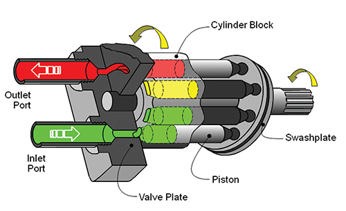
Swashplate type axial piston pump as shown in the diagram consists of a rotating cylinder barrel, which consists of a piston arranged on it axially. The piston ends are connected to an inclined swashplate.
Bent axis type piston pump consists of a cylinder barrel, which carries pistons arranged on it axially. The piston ends are connected to a flange by ball joints.
Screw type pumps use screws to transmit fluid from suction to delivery port. The fluid is carried forward to the discharge by the screw, very much similar a nut moves along a screw. The helical grooves on the screws serve as the path for fluid from the suction chamber to the delivery chamber.
The ball piston pump is a very simple pump design. It has a rotor, which revolves around an internal stator. The rotor has twelve cylinders machined out of it, and each cylinder has a ball inside, which can slide in and out of the cylinder. The cylinder passes over the intake port for 180 degrees, then passes over the outlet port for 180 degrees.
The balls ride along two railed tracks, machined into the outer housing, the balls revolve around the pump in a perfect circle. Because the center point of the circle on which the balls revolve around is offset from the center point of the stator and the rotor, the balls, and the rotor have a relative motion to each other. This relative motion increases and decreases the volume of each cylinder, allowing the mechanism to draw in fluid during a one-half cycle and expel it during the other half cycle.
This pump has a major advantage of high efficiency due to lower mechanical losses. The manufacturing of this pump requires a high degree of precision and accuracy.

If you’re a pump sprayer operator and you’re performing a soft wash application on a two-story residential home to remove lichen or mold, how do you get the spray pattern to reach the eaves of the home and provide even coverage without having to climb a ladder?
There’s a common misconception that to achieve a broader vertical or horizontal spray pattern, you simply need a pump that puts out more pressure. On the contrary, increasing the flow rate is often the key.
It’s not uncommon to hear pump operators complain that their sprayer doesn’t have enough pressure when, in fact, the issue is the flow rate. In fact, some people use the two terms interchangeably, as though they’re the same thing. They’re not, and knowing the difference and the role each plays is the key to achieving proper pump performance.
A pump’s job is not to deliver pressure; rather, it is to deliver a rate of flow, pumping a certain amount of liquid over a given amount of time from a tank or reservoir to the outlet. Flow rates are often referred to in gallons per minute or GPM. There are some smaller pumps that rate flow at gallons per hour or even gallons per day, outputting extremely small amounts of fluid over a given time.
Pump pressure, however, is a measure of resistance to flow. Without flow, there is no pressure. In a positive displacement pump, such as a plunger pump, the rating in pounds per square inch, or PSI, outlines how much resistance the pump is designed to withstand.
A pump’s PSI rating is important because it indicates that the pump was manufactured out of materials and designed to handle a certain amount of pressure. But for pump operators, they should be equally concerned with a pump’s flow rate which determines how much you want to dispense, spray, or inject.
In general, when pump pressure increases, flow will decrease. Take, for example, a misting pump that needs to produce an ultra-fine mist for cooling or dust suppression. Many misting pumps are rated at 1,000 PSI, yet their flow rate is quite low at .25 GPM.
More pressure changes the velocity of the fluid, but it also decreases the flow or output. The cause of the flow decrease is due to two factors: volumetric efficiency of the pump and reduced motor speed. Volumetric efficiency is a measure of the actual flow compared to expected theoretical (calculated) flow — volumetric efficiency decreases as pressure increases. Our positive displacement plunger pumps have about 90–100% volumetric efficiency compared to centrifugal pumps that range from 0–100%. This means that plunger pumps only lose about 10% of the flow when pumping against back-pressure, while centrifugal pumps will lose all the flow when pressure climbs too high.
Reduced motor speed occurs when motors are loaded heavier. So, when pressure in the pump causes more load on the motor, it slows down. When the motor slows down, the flow rate drops at the same percentage. A motor that operates at about 2000 RPM at low pressures will typically slow down to about 1750 RPM when the pump is pressurized to the maximum rating.
It stands to reason, then, that increasing pump pressure will not increase flow. In the soft wash example, more pressure won’t help the operator reach the eaves of a two-story home with the same amount of coverage. The operator needs a pump motor with an ideal combination of pressure and flow.
Engineering pumps for any application requires an understanding of fluid dynamics, and each industry has varying needs. Too often, a company will choose an off-the-shelf high-pressure pump to get a job done and wonder why it doesn’t perform as expected. It’s likely because the operators lack a full understanding of the relationship between flow and pressure.
The engineering experts at Pumptec have a thorough grasp on fluid dynamics and help OEMs and pump distributors pinpoint their exact needs. They make recommendations based on scientific principles and years of experience serving multiple industries, and can even customize pumps to your application’s precise needs.
In fact, we’ve developed a Guide to GPM and PSI that provides some of those industry recommendations. Take a look through it and then contact the pump experts at Pumptec. We’ll be happy to discuss your needs and determine the right pump for your application.

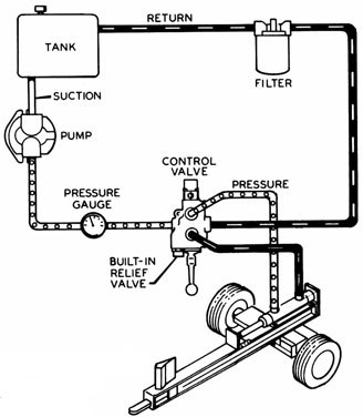
A directional control valve with optional pressure kickout feature controls a double acting cylinder. A pressure gauge is recommended to help spot potential system problems. The tank should be at least one and a half times the pump gpm output and the oil level must remain above the pump intake at all times. (See Logsplitter Safety for more detailed information.)


 8613371530291