
simple hydraulic pump diagram for sale
I. Fixed Displacement Pump – These pump has a set flow rate means every stroke of the motor moves same amount of fluid. Fixed displacement pumps are perfect for single jobs that to be repeated indefinitely over long periods of time. There are three types of fixed displacement pump : Gear Pump, Gerotor Pump, Screw Pump.
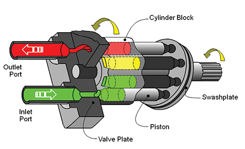
II. Variable Displacement Pump – In Variable displacement pumps flow rate and outlet pressure can be changed as the pump operates. They are used to power a wider variety of tool, but require more expense and more attention. There are four types of variable displacement pump: Bent Axis Pump, Axial Piston Pump, Radial Piston Pump, Rotary Vane Pump.
A hydraulic motor is a mechanical hydraulic actuator that converts hydraulic energy or hydraulic pressure into torque and angular displacement / rotation.
Hydraulic cylinder is a mechanical hydraulic actuator that converts hydraulic energy or hydraulic pressure into linear displacement. It consists of cylindrical barrel, piston and piston rod.
I. Pressure Relief Valve – They are designed to protect hydraulic system when pressure in the system increases beyond the specified design pressure or maximum working pressure. They are normally closed and it opens when the pressure exceeds a specified maximum value and diverts the pump flow back to reservoir or tank internally. They are located near hydraulic pump.
II. Pressure Reducing Valve – They are design to limit and maintain outlet pressure. They are normally open and closed if the pressure exceed beyond specified design pressure at outlet. They are located near hydraulic actuator.
IV. Counterbalance Valve – Counterbalance valves are used in hydraulic systems working with running-away or suspended load. They are designed to create backpressure at the return line of the actuator to prevent losing control over the load.
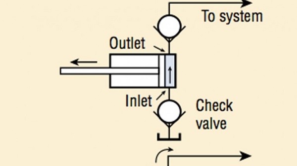
I. Check Valve– check valve or non return valve are simplest type of directional control valve used to allow free flow of fluid in only one direction.
They control the returning flow in relation to the flow being directed into opposite side of the actuator. It is used in hydraulic system to influence the speed of hydraulic motor and hydraulic cylinder independent to the load (prevent running away).
It is a electro mechanically operated valve. The valve is control by electric current through a solenoid. The function of solenoid valve in hydraulic system is to shut off, distribute and release fluid.
Sound crazy or impossible? Don"t worry, it does obey the laws of physics, but I"ll try to explain the operation later. This instructable shows how to build a fairly simple water pump that needs no energy input other than water flowing from a higher point to a lower point. Most of the pump is constructed from PVC, with a couple of bronze pieces thrown in for flavor. I was able to source all of the parts from a local hardware store (Lowes) for a bit under $100.
To function, the pump does require a reasonable amount of water that will drop at least 3"-5". The level that the pump can raise water to depends on the water"s head (total drop the water will make).
Old Bicycle InnertubeThis parts list comes directly from the Clemson website. I recommend you look there for help in identifying what each of the pieces look like, if you"re unsure. I"m also not convinced that the 100 PSI gauge, or all of the things that make it possible, are necessary. This will probably drop the price a good bit, and I haven"t found a need for it on my pump. The associated pieces are: 100 PSI gauge, 3/4" Tee, 3/4" x 1/4" bushing, the 1/4" pipe cock. Four things not needed. But have them if you like.
Now that you"ve bought lots of goodies, lay them out on the table (or floor) so that you can start to see how the pump goes together. See the pictures for a visual on this.
While you"re at it, you might as well clean up the edges on the other sections of pipe, though it will be less critical for the other parts. Now that you"ve got all the connecting segments, you can actually test fit the first part of the pump together, just for fun.
Once you"ve got cement where you want it (and hopefully only a little where you don"t) fit the pipe into the fitting. It should slide in without too much resistance. When working on my pump, I felt that it was best to clamp up each piece after I had assembled it, that way the pipe couldn"t slip back at all. It may not be necessary, but I figure it helps.
I began at one end of the pump, with the 1-1/4" valve to the 1-1/4" union. You can choose to start with other pieces, but I found that setting up the main line gave me something easy to clamp up. After the 1-1/4" to 3/4" bushing is on this tee, you can glue up the end assembly separately, and then connect it to the main assembly with the threaded 3/4" pipe.
Now you need to put together the pressure chamber. Gather up your big pipe section, cap, adapter, bike tube, and bike pump. Using the pump, partially inflate the bike tube. Don"t pump it up all the way, just enough that the tube is squishy. We need the air in the pressure chamber to act like a spring.
Some may choose to omit the bike tube, and just drain the pump out every once in a while. That"s totally possible. It"s also possible to either mount a schrader valve onto the end cap of the pressure chamber to recharge it. Whatever suits your fancy, but this setup worked fine for me so far.
If you haven"t done it already, install the brass swing check valve. Make sure that the flapper (I just like calling it that) is hanging down, when the pump is held upright (everything pointing upwards). The whole thing should just thread onto the bushing that you"ve cemented to the end of a 1-1/4" pipe. Simple enough.
After that, you may break out the flapper dress, cut your hair short, and swing dance the night away celebrating the reckless spirit of the Jazz Age (and completion of your pump). You party animal you.
Now that you"ve got a rather aggressive looking collection of PVC bits, it"s time to make it do something. You"ll need to attach the stand pipe (the long section of 1-1/4" pipe) to the 1-1/4" union with cement, and then decide how you want to hook the other end to your water source. My first method was a chopped up milk jug. Honestly, I just wanted to see this thing pump some water.
Gather up a garden hose, your stand pipe, and your pump, then drag all of this out to your waterfall or what have you. Bring a friend or two. They help in the setup, and maybe you can win the bet that "you can pump water above the source without electricity, gasoline, diesel, a bicycle, or a bucket while they watch."
At this point you can probably figure it all out on your own, but you"ll need to get the water flowing down the stand pipe, which you"ve connected to the main pump, and then up through the swing check valve. On to the next step for theory of operation, troubleshooting and tuning.
When you install this permanently (or semi-permanently), you"ll want to find a good place to anchor it to, probably not in the stream. Place it as low as possible, but keep in mind that if the stream were to flood and / or a tree to wash down it, it would take your nice little pump off with it.
Also, for those in the northern (or far southern) latitudes, you won"t want this to be running during the winter. Water could potentially collect inside the pressure chamber and freeze, causing you problems (untimely death of pump). But experiment as you feel fit.
The video here is playable using Quicktime. Presently, you have to save it to your computer, and change the extension (bit after the long strange file name) from .tmp to .3gp. I"m sorry it"s being difficult, maybe someday I"ll set it up with an embedded player, but right now I"m short on time. It shows the pump working, with narration by yours truly. Gives you an idea of what it sounds like standing in the water right next to it, and also has a close up of the swing check valve working.
As the pump cycle begins, water flows down the stand pipe, and up through the swing check valve. Water begins to flow faster and faster around the flapper in the check valve, until friction draws the flapper up, slamming it closed. This causes a pressure spike in the pump body, as the water flowing down the stand pipe at some speed no longer has anywhere to go. This pressure is relieved by some of the water flowing across the spring check valve, over onto the pressure chamber side of the pump. Once past the swing check valve, it cannot return, and has to stay there. When the pressure difference across the spring check valve drops, the valve will close and water will stop flowing through it. The lower pressure will allow the swing check valve to open again, beginning the cycle all over again.
Sometimes water will flow out of the swing check valve, then the valve will slam closed, but nothing will happen. If this occurs, tap on the flapper in the check valve to open it up again, and let the cycle begin again. In theory these pumps need some back pressure (coming from the pressure tank side) to operate, but I"ve never had any trouble getting mine going with just some basic tapping and fiddling.
Now that it"s working, can you make it work better? You"ll find that there"s a maximum height that the pump can deliver water to. Be patient when trying to find this, as it takes a little while for the pump to achieve the pressure required to raise the water up higher and higher. There are formulas that will tell you how high you can theoretically pump water based on the source water head. Feel free to look them up.
Tuning ram pumps mostly involves varying the water velocity that results in the swing check valve closing. A higher water velocity will generate a larger pressure spike, allowing you to pump to greater heights. But it will also cause a slower cycle, so you pump more slowly. If the valve closes at a lower water velocity, it will take less time for the water to reach that velocity, so the pump will cycle faster, and the water pumped faster, but you will not be able to pump as high. So that"s the trade off. Keep in mind though, that this will work without interference 24 hours a day, so combining it with a holding tank, you can get a decent supply of water built up.
To tune this specific design, you take advantage of how gravity acts on the flapper. When the check valve is pointing straight up in the air, the full force of gravity holds the flapper down, so the water must flow past the flapper faster to generate enough drag to raise the full weight of the flapper. By rotating the pump about the main line, you put the flapper"s degree of freedom at an angle to the force of gravity, so that less drag is required to move the flapper. You could work out all of this fairly easily with a bit of trig, but I feel it would serve you little use out in the field. Just play around with it, you should find a position that works well for your application.
Well, no. This pump derives its power from the potential energy of the water uphill, and by wasting (not in a bad sense) the majority of the water that flows through the stand pipe. It only pumps a small fraction of the water that actually travels down that pipe. But that"s fine if you have a stream already flowing down a hillside. Before, you weren"t doing anything with all that potential / kinetic energy. Now you are. Hooray for you!
Hi Guys Can any one tell me what the sizes are when I make a 40mm (1./12") ram pump. mainly the size of the pressure chamber and how long. A complete list would be appreciated.0
The power for a ram pump comes from the head pressure, how far the water drops before reaching the pump. The flow of a stream, unless it can lift water up a pipe won"t be sufficient; however, a dam can be constructed if you can"t find or make a spot lower than the water level in the stream. Ponds and lakes typically have dams (natural or man-made). Below the dam is the best place for the pump. If you can put the drive pipe through the dam this would be ideal, otherwise, getting the water to flow over the dam is as simple as drawing water through the drive pipe until it is below the level of the water held back by the dam using a process known as siphoning. Yes, sometimes your mouth is the best tool to draw the water through the pipe, just be ready to get a mouthful of water (and possibly muck or scum).
The lift of a ram pump is 6 times the head pressure, so if the feed water drops 1 unit (feet, meters, whatever) it can be pumped uphill 5 units above the level of the feed source.0
I have a small creek behind my house and want to know if this 1 1/4” ram pump will be large enough to furnish enough water to supply a small waterfall?0
you need to use a actual spring check valve. A low pressure spring will suffice. if what im seeing in the photo is correct the swing check that is being used will only give you grief. they are designed for a horizontal install with the "flapper" always hanging down. A spring check will make sure you have the back pressure to close the valve when needed so your pump is able to work its magic. good luck everyone. I hope this helps. If I have repeated anyone please forgive me, i caught this in passing. these pumps are great. thanks for sharing the build1
Ok.. we built the thing !! We have tried so mary ways of making this work but I guess we just aren’t getting the gist of how it works to make it work !! We have a creek .. we have the hose going into it.. but the flapper never flaps !! It just flows out the overflow!! We have poked the flapper many times and that don’t seem to help ?? So we are at our wits end and need help !! A written diagram for dummies would be helpful !! Lol ty for any help !!
My guess - You probably don"t have enough back pressure. Either you need much faster moving water, or you need a larger diameter hose feeding the pump. If you take a look at this similar ram pump, it says it requires 8 gpm and a 1-1/4" prive pipe.0
Hi further to my previous comment my husband ha finished making the ram pump. He made a few minor adjustments and it is working like a dream. It hasn"t missed a beat. We installed anew 11,200 litre water tank and it filled it in just over 4 days. Your instructions and photos are invaluable and anyone that has the means to utilise water in this way, don"t hesitate. It puts us another step closer in self sufficiency. Great work and thank you for sharing.
Thank you for sharing your amazing ram pump. Very impressed. We are using a Billabong brand which is Australian made. Having a few issues so we are going to give yours ago. Off to Bunnings tomorrow to get some fittings. They are an amazing concept and they sound good also. Thanks again0
Below are some common illustrations of equipment located on fluids circuit diagrams, followed by descriptions of the most common elements. Later in this article series we will describe some simple hydraulic and pneumatic circuits composed of these circuit elements.
Hydraulic pumps are used to pump oil from the power unit to other parts of the hydraulic system. Some pumps have control options such as pressure or flow compensators.
Heat exchangers are used to remove heat from the circulating oil in the hydraulic system. The most common heat exchanger is water-to-oil but some times air-to-oil units are used. Coolers will cool the fluid.
Proportional valves are electrically controlled hydraulic valves. These valves proportionally control the hydraulic pressure and/or flow based on an electrical input signal.
For more information about reading hydraulic and pneumatic circuit diagrams, read the next article in this series which describes sample hydraulic circuits, or contact your Valmet representative.

Here are some Details of diagram,12vdchydraulic circuit diagram and electrical diagram. And more, AHydraulic Power Pack.This Wireless Remote can be with a quick connector ,can be changed with our standard 2 buttons remote easy since the quick connector is on the power pack.

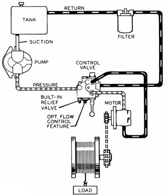
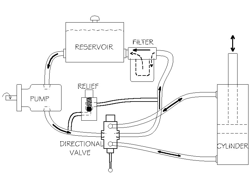
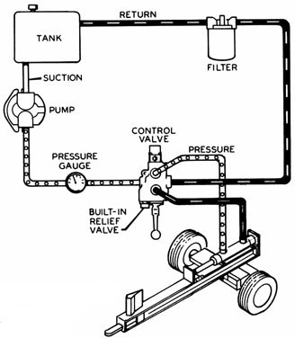
The cylinder is driven by hydraulic oil, under pressure, produced by a hydraulic pump. An engine, or electric motor, drives the pump shaft, and supplies the power for the system. The oil from the pump runs to a hydraulic valve, which provides control over the movement of the cylinder.
The oil source is a hydraulic reservoir (tank) which is connected directly to the inlet port of the pump. Most use AW32 viscosity (approx 10 wt.) hydraulic oil, which is of course an important part of any hydraulic system. There is a vented filler cap on the reservoir which allows air to “breathe” in and out. A simple air filter in it keeps dirt out.
A hydraulic relief valve controls the maximum pressure which can be created by the pump, and is a safety valve. It is usually located within the housing of the directional control valve. It is rarely in the pump. Without a relief, most hydraulic pumps will build pressure until something breaks, like a hose, or the cylinder, or the pump itself.
Most log splitters use a 2-stage gear pump which is a special type of hydraulic pump. They are rarely used in any other hydraulic systems. But they are widely available and relatively cheap because so many are sold for logsplitters.
Let’s start with the basics. Gear pumps are the most common, and least expensive type of hydraulic pump. They consist of 2 shafts, each with a gear which meshes with its twin to drive oil from the inlet port to the outlet or pressure port. Oil is trapped in the cavities between the gear teeth and carried around the outside of the gear toward the outlet port. The meshed gear teeth in the center keep oil from returning to the inlet side. One shaft sticks out of the housing and is driven by the engine. The other shaft is hidden within the pump housing. The one gear drives the other.
Two stage pumps give splitters great performance using small engines. A 2-stage pump consists of 2 gear pumps in a single housing, and a bypass valve. One gear set is about 3 times the size (length) of the second. When the valve is in neutral & system pressure is low, both gear sets are pumping oil into the system. With a “16 GPM” pump, they will pump 16 GPM when the pump shaft is rotated (by the engine) at 3400 RPM. That is, the combination of the outputs from both gear sets equals 16 GPM.
When the valve is shifted it moves the cylinder quite quickly. But when the log hits the wedge, the resistance increases, and pressure is backed up against the pump. Now the bypass valve comes into play. When the back pressure reaches 700 – 800 PSI, oil from the larger set of gears is allowed to pass back to the inlet side of the pump (at almost 0 PSI) rather than being forced out the pressure port. So the only oil being forced out is from the small gear set. This takes a lot less horsepower and allows the use of a reasonably small engine to develop the high pressure necessary to split wood, while giving the cylinder good speed when not under a heavy load (which is most of the time). The opening and closing of the bypass is automatic, activated by the oil pressure. It’s so smooth it’s usually difficult to notice it is happening. So 2-stage pumps give our log splitters the best of both: high pressure when we need it, and high speed the rest of the time.
We sometimes see home made log splitters with single stage pumps, often reused from another type of machine. They are usually quite slow unless a much bigger than normal engine is used.
The cylinder is the “actuator” of the system: it converts the hydraulic pressure and flow into force to split the wood, and speed to make it efficient. The larger the cylinder diameter the more force (tonnage) it puts out, but the slower it will go: it takes more oil to fill, and so takes longer.
The most common size for log splitters is “4 x 24″, 4″ bore by 24″ stroke. With 2500 PSI from the pump it can exert over 31,000 lbs of push force. To compare, a 5″ bore cylinder can produce 49,000 lbs force with the same pump, over 1 1/2 times as much. But the 5” cylinder will go 36% slower, which is why they are not common on ordinary splitters.
1. Pushed one way it shunts oil from the pump to the base port of the cylinder, causing it to extend. And it simultaneously allows oil from the rod-end port of the cylinder to flow into the return line.
2. When let go, the spool springs back to the neutral position; the oil from the pump is allowed straight through to the return port where it is recycled back to the tank, and the cylinder ports are blocked so the cylinder is stopped and held in position.
The relief valve consists of a heavy spring with a compression adjustment screw, and a ball or poppet against a seat. This is in a channel between the pressure inlet port and the return port, with the ball or poppet blocking the flow. If the oil pressure reaches the adjustment setting, perhaps 2500 PSI, it overcomes the spring pressure, the poppet backs off, and oil from the pump is allowed to bypass directly to the valve outlet, thus limiting the maximum oil pressure in the system. At normal working pressures, the relief remains closed and is not involved in the circuit.
The hydraulic oil for the system is stored in a tank, usually steel. Reservoirs serve two important functions: They allow the oil to settle any air bubbles and contamination particles; and they allow the oil to cool while it’s not circulating.
To provide sufficient cooling, the tank should be sized to hold at least one minute’s worth of oil. (16 gallons for a 16 GPM pump.) Oil which is too hot, 180F, will harden seals, and will be too thin to lubricate the spinning pump parts, causing early pump failure. We recommend 150F as the working maximum oil temperature.
The suction and return ports should be on the sides of the tank, a couple of inches above the bottom to avoid any sludge which may have settled there. The suction line should be low enough to never ingest any air, and the return should be low so as not to stir any air into the oil. Further, the 2 ports should be separated enough to avoid the hot returning oil from being immediately sucked back into the pump line.
Every good hydraulic system has a filter to remove fine contamination particles from the oil. The recommended rating is 10 microns, (10 microns equals 0.00039 inches; about 1/5 the diameter of a human hair). A filter this fine would plug the suction line, so it must be installed on the return, typically right at the tank return port.
Suction strainers in the tank are 100 micron or more, so can not catch the fine, damaging particles like the return filter. And if they get plugged they may starve the pump, greatly shortening its life. They are not recommended.
Hydraulic oil is blended with chemical additives beneficial for hydraulic systems. They help resist wear, shed contamination, maintain viscosity when cold, resist foaming, rust and oxidation, etc. Typical viscosity is around SAE 10, usually labelled AW32.
Hydraulic oil is not subjected to the burning temperatures of combustion engines, so it usually lasts a long time. The recommendation is to change oil if it is excessively dirty, or milky (water contamination) or smells bad or burned. If not, it’s better to just change the filter and save the cost of an oil change.
How to get more force? Either more pressure, or a larger cylinder. The pressure you probably can’t change much. Check the relief setting on your directional valve. It controls the maximum. We don’t suggest more than 2500 PSI, which is the practical maximum for most gear pumps. Yes they are sometimes rated at 3000 PSI or more. But that’s like driving your car 125 MPH. It may be able to do it, but all the time? Not such a good idea. Virtually all logsplitter pumps are rated for the same pressure. What’s the difference between pumps? Bigger gears, which produce more flow, which means more speed. And requires more horsepower to drive them. To get more force, you’ll need a larger bore cylinder. If you want the same speed as a smaller cylinder, you’ll need a larger pump, and probably a larger engine to drive it.
How to get more speed? Either more flow (GPM), or a smaller cylinder. The smaller cylinder won’t require more power, but will produce less force. More flow comes from a larger pump. So you’ll get the same force but will need to supply more horsepower to the new pump.

HYDRO-PACK LTD is dedicated to engineering, manufacturing, warehousing and distributing fluid power products located in “City of Roses” Kazanlak, Bulgaria and has business connections on all over Asia, Europe, Middle East and Africa in hydraulic field. We carry on the activity under Hidros Group, Turkey and branch offices in Turkey, Germany and South Africa. Our wide product range includes hydraulic gear pumps, directional control valves, hydraulic valves, hydraulic motors and steering units, hydraulic power units, oil coolers, pump over gears, slewing drives, piston pumps, tractor and forklift replacement parts. We export our products to more than 60 countries.

The basic hydraulic suspension is made up of a few different car hydraulic parts. Each one provided by CCE gives you ultimate performance, reliability, and budget consciousness.
Our expert technicians are trained and have the knowledge to answer any questions you may have about your current lowrider hydraulic parts or installing a new system.
Dump(s): Dumps are the valves that control the hydraulic fluid. They are responsible for directions the pressurized fluid into the cylinders to lift (or dump) your vehicle.
Our lowrider hydraulic parts, from pumps and motors to hydraulic fittings and hoses, offer the best combination of technology and reliability that translates directly into unbeatable performance.
Hydraulic control serves almost all industries we can see around us, such as civil engineering, aerospace, military, agriculture, oil and gas, etc... This 27-hour (5-day) seminar overviews components and basics of building hydraulic systems. The core part of the seminar covers the construction, operating principle, and sizing of basic hydraulic components such as pumps, motors, valves, cylinders, rotary actuators and accumulators.
The course also presents the terminologies and interpretation of symbols that help in reading hydraulic circuit diagrams. The seminar presents detailed discussion about line losses, and sources of inefficiencies in pumps. The course concludes by exploring the basic techniques to build hydraulic circuits that work safely and efficiently. The course covers basic applications such as pressure limiting, pump unloading, driving single and multiple actuators against, resistive, overrunning, and combined loads. Other applications are covered such as sequence control and hydrostatic transmission.
This seminar presents wide foundational understanding of hydraulic systems. Both inexperienced and experienced people should take the course where everyone will have some space to learn things based on their needs. Despite being named "introduction," the contents of the seminar are certainly beyond that. The target audience is engineers, technical sales personnel, technicians, and even management personnel.
Anyone who has been manually chopping up wood with an axe will realise how labour intensive it is. Necessity is the mother of invention and, in this case, the answer was the hydraulic log splitter

The Power Team P-Series hand pumps come in a variety of configurations to meet the requirements of your application. Along with various oil capacities and flow rates, you can choose from the following options:
Compact design ensures that the Power Team PA6 series pump is lightweight and portable. The PA6 series consists of single-speed pumps designed to drive single-acting cylinders. The power unit of choice for major manufacturers of auto body, frame straighteners and other equipment. Operates at 40-100 psi (3-8 bar) shop air pressure at the pump, dBA 85 at 10,000 psi (700 bar). Serviceable pump motor is not a “throwaway”, providing economical repair. Permanently vented reservoir cap. Internal relief valve protects circuit components, air inlet filter protects motor.
Compact, lightweight and portable the Power Team PA6D series pumps are single-speed pumps for driving double-acting cylinders. The PA6D series pumps operate at 40-100 psi (3-8 bar) shop air pressure at the pump. Designed with longevity in-mind the PA6D series feature internal relief valve protects circuit components, air inlet filter protects motor. Serviceable pump motor is not a “throw away”, providing economical repair. Permanently vented reservoir cap. dBA 85 at 10,000 psi (700 bar) for all PA6 pump.
Ideal for powering single-acting cylinders and portable hydraulic tools, the Power Team PA9 series pumps are easier to operate than a hand pump, designed for efficiency. Built to be economical in service; the PA9 series is not a “throwaway” unit. Unique bladder design for all-position operation and storage. Operates on 40-120 psi (3-8 bar) shop air, at 20 cfm (570 l). Hard-coat anodized aluminum housing. Oil filler with integral safety relief minimizes chance of damage to reservoir bladder if overfilling occurs.
A two-speed pump, the Power Team PA60 series pumps are designed for rapid oil delivery at low pressure to quickly advance cylinder or tool. Equipped with air pressure regulator, air filter and lubricator. Serviceable air motor for economical repair. Internal relief valve protects circuit components. Permanently vented reservoir cap.
Focused on single-speed and low pressure the Power Team PA50 series pump outputs 3,200 PSI / 220 BAR, fitting serviceable requirements for air motor for economical repair. Integrated air inlet filter protects motor. The PA50 series also features a filter in outlet port protects against contaminated systems Assorted reservoirs to suit your application"s requirements.
Rotary-Style Air Motor. Use where air is the preferred source of energy. 3 hp motor starting under full load. Two-speed operation for rapid cylinder advance. Models available with full remote control over advance and return, except PA554. Tandem center valve holds the load when pump is shut-off.
Compact, Portable, Cordless Hydraulic Pump for MRO Applications. Compact, Li-ion 18VDC, 9.0 Ah battery-powered pump provides extended run-time. Two-stage, high-pressure hydraulic pump offers quick tool advancement in the first stage. Extremely compact, lightweight with an ergonomic handle grip and transport strap to ease portability. Self-contained, rubber bladder reservoir allows pump usage in most positions with an impressive capacity of 70 cu. in. usable. Quiet, smooth-running, serviceable brushed 18VDC motor. High-impact, fiberglass reinforced shroud protects your investment in the most demanding and harsh applications. Interchangeable valve configuration accommodates a vast array of applications. CSA rated for intermittent duty, CE compliant.
The 10 series Power Team hydraulic pumps are designed to have a maximum of 690 bar (10,000 psi) at a flow rate of 164 cc/min (10 cu. in/min). All Power Team pumps come fully assembled, and each with the ability to be valved for either single- or double acting cylinders. Designed to be compact can easily mobile, the power team 10 series includes a portable power source is included for hydraulic cylinders, and tools. The permanent magnet motor is strategically constructed to easily start under load, even with reduced voltage conditions. Battery-operated models have 8 foot (2,4 m) power cord with alligator clips to connect to any 12 volt battery, optional rechargeable battery pack with shoulder strap are alternatives for maximum portability. The Power Team 10 series pump typically delivers 15 minutes of continuous operation at 10,000 psi (700 bar) on a single battery. Built to withstand High-impact, shielded with a flame retardant construction.
The Power Team 17 series pump is delibertly designed for maintenance and construction applications up to 55 Ton. For use with single-acting or double-acting cylinders at operating pressures to 10,000 psi (700 bar). For intermittent duty; starts under full load. Equipped with 1⁄2 hp (0,37 kW), 3,450 rpm, single-phase, thermal protected induction motor; 10 ft. remote control cord (PE172S has 25 ft. (7,6 m) cord) Low amperage draw; small generators and low amperage circuits can be used as power source. Extremely quiet noise level (67-81 dBA).
Vanguard Jr. + Power Team 18 series pumps provide two-speed high performance in a light-weight, compact package. Designed to provide a gauge port and metal reservoir on all pump models. Equipped with a 1⁄2 hp (0,37 kW), 115 volt, 60/50 Hz single phase motor that starts under load, even at reduced voltage. Low amperage draw permits use with smaller generators and low amperage circuits. All pumps have a 10 foot (3 m) remote control. CSA rated for intermittent duty. Noise level of 85-90 dBA. For operating hydraulic crimping, cutting or other tools: No. PE184C - Allows you to alternately operate a spring-return cutting and/or crimping tool without disconnecting either tool. Select a port connection with a manual 4-way valve, start the pump with a remote control hand switch and extend the connected tool. When the hand switch is switched to off, the pump stops and the automatic valve opens, allowing the tool to return. In the center (neutral) position, a manual control valve holds the tool in position at the time valve is shifted.
The 21 series Power Team pump and RD5513 cylinder used in a special press that produces pharmaceutical-grade extracts for herbal medicines. Totally enclosed, fan cooled induction motor: 1 hp (0,75 kW), 1,725 rpm, 60 Hz, single phase. Designed intentional for thermal overload protection. Remote control, with 10 foot (3,1 m) cord is standard on pumps with solenoid valves. Manual valve pumps have “Stop”, “Start” and “Run/Off/Pulse” switches. Pump controls are moisture and dust resistant. Motor drip cover with carrying handles and lifting lug. Low noise level of 70 dBA@ 10,000 psi (700 bar). In the event of electrical interruption, pump shuts off and will not start up until operator presses the pump start button. 24 volt control circuits on units with remote controls provide additional user/operator safety.
Ideal for running multiple tools or cylinders from one power unit. Recommended for cylinders up to 75 tons. Two-speed pumps have the same low pressure and high pressure flows from both valves. Flows and pressures of each pump are independent. Delivers 300 cu. in./min. of oil at 100 psi (4,8 liter/min of oil at 7 bar) and 25 cu. in./min. at 10,000 psi (0,4 liter/min at 700 bar) from each pump. 1 1/2 hp, 110/115 volt, 60 Hz (1,12 kW, 220 volt, 50 Hz) induction motor, 10 foot (3,1 meter) remote control and 5 gallon (19 liter) steel reservoir. Models available for operating single-acting or double-acting cylinders. Each power unit contains two separate pumps and two separate valves allowing operator to control multiple processes with one power unit. Both pumps on each power unit are equipped with an externally adjustable pressure relief valve. Not recommended for frequent starting and stopping.
The Power Team 30 series pump is intently ideal for maintenance and construction applications. Operating both single-acting or double-acting cylinders. A dynamically built, Integral roll cage protects the 30 series pump from many forms of damage. 1 hp (0,75 kW), single phase, permanent magnet motor. High performance to weight ratio. Starts under full load even when voltage is reduced to 50% of nominal rating. Quit operations: 82 dBA @ 10,000 psi (700 bar) and 87 dBA @ 0 psi (0 bar). CSA rated for intermittent duty. Remote controls and/or solenoid valves feature 24 volt controls.
The Power Team 46 series is best suited for under the roof maintenance and production applications. Equipped with two-speed high-performance pump, for use with single- or double-acting cylinders at operating pressures to 10,000 psi (700 bar) the 46 series pump is versitile. With a 1 1⁄2 hp (1.12 kW), 3,450 (2,875) rpm single-phase, 60 (50) Hz thermal protected induction motor that starts under full load. Noise level of 77-81 dBA. All equipped with a 10 foot (3,1 m) remote control except PE462S which has a 25 foot (7,6 m) remote control. 24 volt control circuit on all units with remote control. CSA rated for intermittent duty.
A powerful multifaceted pump, the Power Team 55 pump excels at multiple applications. From heavy construction to concrete stressing this pump series is designed for intensity. With low voltage starting possible, the 50/60 Hz universal motor; draws 25 amps at full load, and can start at reduced voltage. CSA rated for intermittent duty. 10 foot (3,1 m) remote motor control (except PE552S which has a 25 foot (7,6 m) remote motor and valve control). True unloading valve achieves greater pump efficiency, allowing higher flows at maximum pressure. Reservoirs available in sizes up to 10 gallons (38 liter). Lightweight and portable. Best weight-to-performance ratio of all Power Team pumps. “Assemble to Order” System: There are times when a custom pump is required. Power Team’s “Assemble to Order” system allows you to choose from a wide range of pre-engineered, off-the shelf components to build a customized pump to fit specific requirements. By selecting standard components you get a “customized” pump without “customized” prices. All pumps come fully assembled, add oil and ready for work.
A compact lightweight pump, the Power Team 60 series is designed for rugged applications and low voltage starting. Experiencing a long, trouble-free life in the most demanding work environments, the 60 series is durable.. Powered by 1 1⁄8 hp, 115 volt, 60/50 Hz (0,84 kW, 220 volt, 60/50 Hz) single phase motor. Starts under load, even at the reduced voltages at construction sites. Optional fan-driven external oil cooler includes rollover guard. Insulated carrying handle. Integral 4" (102 mm) diameter fluid-filled pressure gauge with steel bezel complies with ASME B40.1 Grade A. 0 to 10,000 psi (0 to 700 bar) pressure range in 100 psi (7 bar) increments. Sealed 3⁄4 gallon (4,34 liter (usable) reservoir. Reservoir drain port is standard. Standard oil level sight gauge for accurate oil level monitoring. External spin-on filter removes contaminants from circulating oil to maximize pump, valve and cylinder/tool life.
The Power Team PQ60 series pumps are designed specifically for heavy-duty, extended cycle operation. Integrating single- or double-acting cylinders the PQ60 series is versatile. Constructed for longevity by employing a metal shroud keeps dirt and moisture out of motor and electrical components. An electrical shut-down feature prevents unintentional restarting of motor following an electrical service interruption. Internal relief valve limits pressure to 10,000 psi (700 bar). External relief valve is adjustable from 1,000 to 10,000 psi (70 to 700 bar). The Power Team PQ60 pumps operate below maximum OSHA noise limitation (74-76 dBA). Start and operate under full load, even with voltage reduced by 10%.
The Power Team 120 series pump is exactingly designed for heavy duty, extended cycle operation up to 400 Ton. Built in grit, the series 120 pump can start and operate under full load, even with voltage reduced 10%. An electrical shut-down feature prevents unintentional restarting of motor following an electrical service interruption. Internal relief valve limits pressure to 10,000 psi (700 bar) and an external relief valve is adjustable from 1,000 to 10,000 psi (70 to 700 bar). Pump prewired at factory with a 3 hp, 460 volt, 60 Hz (2,24 kW, 380 volt, 50 Hz), 3 Phase motor. Other electrical configurations are available. 24 volt control circuits on units with remote controls for added user/operator safety. 3 hp (2,24 kW) 3 phase motor with thermal overload protection. Motor starter and heater element supplied as standard equipment; with an intentionally designed metal shroud to keep dirt and moisture out of motor and electrical components. Pumps operate below maximum OSHA noise limitation.
With high tonnage double-acting cylinders, the Power Team 400 series offers both single or multiple cylinder applications. Two-speed high output pump delivers up to 5 gpm (16 liter/min) of oil, with a low noise level of 73-80 dBA. Integral electrical shut-down feature prevents unintentional restarting of motor following an electrical service interruption. Over-current protection prevents damage to motor as a result of overheating. “Stop” and “Start” control buttons are 24 volt. PE4004 has a 4-way/3-position manual valve. The PE4004S has a 4- way/3-position solenoid valve with a 24 volt remote hand switch. External pressure relief valve is adjustable from 1,500 to 10,000 psi (100 to 700 bar). Heavy duty 4" (50,8 mm) diameter casters assure easy maneuvering. 20 gallon (3,927 cu. in. usable) / 75,7 liter (62,8 liter usable) reservoir has a low oil level sight gauge. Powered by a dual voltage 10 hp (7,46 kW), 3 phase, 1,725 (1,437) rpm motor. 3 phase motor has all the electrical components necessary to operate the pump.The customer has no hidden charges when making purchase. Deliver 1,200 cu. in./min. (16 liter/min) of oil @ 200 psi (15 bar), 420 cu. in./min. (5,6 liter/min) of oil @ 10,000 psi (700 bar).
Power team synchronized lifting and lowering system, the MCS ( motion controller system ) series can be used in many hydraulic applications where load position is critical, requiring cylinder synchronization. Whether it is a bridge, a building or any kind of heavy load, with the SPX FLOW power team motion control system, lifting, lowering, pushing, pulling, tilting or positioning loads can be carried out automatically with a high degree of accuracy. The PLC-controlled system is a combination of digital actuation and digital control providing significant advantages such as time savings, repeatability, and extremely low internal stress in the object one is moving. The system also provides documentation for the movement performed.
Extremely durable yet lightweight and operable under low-line voltage conditions, the Power Team PE-NUT series pumps are constructed for challenging conditions. A 115V 5/8 hp (0,46 kW) universal electric motor (50/60 cycle), employing a two-stage pump for efficiency and designed for use with spring-returned remote tools. The PE-NUT series pumps also feature high-pressure safety relief valve, remote hand control with 10-foot (3,1 meter) cord, and a pressure matched quick-coupler supplied. The PE-NUT series uniquely utilizes intermittent duty, piston-type high-pressure pump supercharged by a low-pressure pump. CAUTION: DESIGNED FOR CRIMPING APPLICATION ONLY! This system should not be used for lifting.
Gasoline power ideal for remote locations. A logical choice at work sites where electricity or compressed air are unavailable. For single or double-acting cylinders at operating pressures up to 10,000 psi. All gasoline engine/hydraulic pumps feature Posi-Check® valve to guard against pressure loss when valve is shifted from “advance” to “hold.”
PG303 is for single-acting cylinders, has a 9520 valve with separate internal return line which allows oil from running pump to return to reservoir, independently of cylinder return oil, when valve is in “return” position.
PG1200 Series pumps powered by a Honda 4-cycle, 5.5 hp engine with automatic decompression and electronic ignition. Deliver over 0.5 gallon (130 cu. in.) of oil per minute at 10,000 psi.
Rubber anti-skid insulation on bottom of reservoir resists skidding and dampens vibration. PG1200M-4 and PG1200M-4D include a pump cart with 12” wheels.
The Power Team HB series is purposefully constructed to convert low-pressure portable hydraulic pumps or on-board hydraulic systems, into high pressure power sources. HB series applications include utilities, railroads, construction, riggers and others. This product operates single or double-acting cylinders, jacks, and tools such as crimpers, spreaders, cable cutters, or tire tools. Version for use with double-acting torque wrenches available. May be used to operate two separate, single-acting tools (with integral valves) independently, without need for additional manifold. Control valve included. Other Power Team valves available as an option to suit your specific application, if needed; consult factory. Compact and rugged for use inside a utility vehicle aerial bucket or stowing in a vehicle. No reservoir level to maintain; uses low pressure system as oil supply. Has 3⁄8" NPTF ports; compatible with standard fittings for low and high pressure systems.
Portable two-speed pump operated in any position (open or closed-center) providing pressures up to 10,000 psi for the operation of high-pressure tools.
These compact, lightweight boosters do not have reservoirs. The units can be operated in any position on either open- or closed-center (accumulator) hydraulic systems.
“Assemble to Order” means you can choose a basic pump with gas, air or electric motor. Then select the proper valve, gauge, pressure control, motor control and reservoir. You get a two-stage pump that gives high oil volume for fast cylinder approach (and return with double-acting cylinders) in the first stage and high pressure in the second stage.
3 HP Jet Motor, Three-Phase. Gives low noise level and long life due to its moderate operating speed. Ideal for fixed installations. Consists of basic 10,000 psi pump, jet pump motor: 3 hp, 3,450 rpm, 230/460VAC, 60 or 50 cycle (specify). AC three-phase, with thermal overload switch. Equipped with internal and external relief valve. Will start under load.
or cannot be used. The 5,000 or 10,000 psi pump has a 3 hp air-driven motor at 3,000 rpm (optimum performance based on 80 psi air pressure and 50 cfm at the pump). You can drive single or double-acting cylinders with the correct valve. NOTE: 80 psi air supply required to start under full load.
unavailable. It is capable of continuous operation at full pressure. Consists of basic 10,000 psi pump, 4-cycle Briggs & Stratton “Diamond Edge” gasoline engine, developing 6 hp. As with all these pumps, this unit can be valved for use with either single or double-acting cylinders.


 8613371530291