
simplex electric hydraulic pump free sample
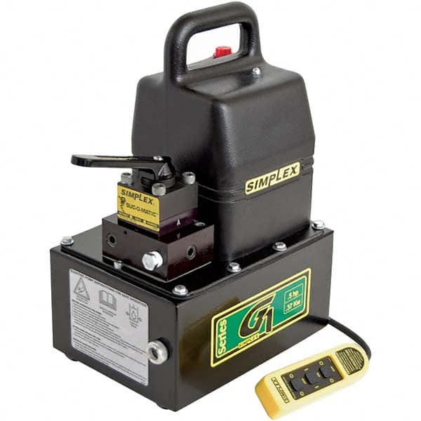
G3 - A 1.13 hp continuous duty power pump that is best suited to power small to medium tools and cylinders. Ideal for systems that require high performance, large oil capacities with lightweight portability.
G5 - Continuous duty 1.5 hp electric pumps are perfect for medium size tools and cylinders. It"s the perfect choice for production and lifting applications due to its reservoir sizes and valve options.
G6 - Continuous duty 3 hp electric pumps are ideal for medium to large size tools and cylinders. The high flow rate runs multiple cylinders for heavy lifting, high tonnage and large positioning jobs and applications effectively.

An intermittent 0.5 hp (0,37 kw) power pump that is best suited to power small to medium size tools or cylinders. It"s very lightweight, portable and works well for crimping, cutting, pressing, punching and bending applications.

Mechanical pumps serve in a wide range of applications such as pumping water from wells, aquarium filtering, pond filtering and aeration, in the car industry for water-cooling and fuel injection, in the energy industry for pumping oil and natural gas or for operating cooling towers and other components of heating, ventilation and air conditioning systems. In the medical industry, pumps are used for biochemical processes in developing and manufacturing medicine, and as artificial replacements for body parts, in particular the artificial heart and penile prosthesis.
When a pump contains two or more pump mechanisms with fluid being directed to flow through them in series, it is called a multi-stage pump. Terms such as two-stage or double-stage may be used to specifically describe the number of stages. A pump that does not fit this description is simply a single-stage pump in contrast.
In biology, many different types of chemical and biomechanical pumps have evolved; biomimicry is sometimes used in developing new types of mechanical pumps.
Pumps can be classified by their method of displacement into positive-displacement pumps, impulse pumps, velocity pumps, gravity pumps, steam pumps and valveless pumps. There are three basic types of pumps: positive-displacement, centrifugal and axial-flow pumps. In centrifugal pumps the direction of flow of the fluid changes by ninety degrees as it flows over an impeller, while in axial flow pumps the direction of flow is unchanged.
Some positive-displacement pumps use an expanding cavity on the suction side and a decreasing cavity on the discharge side. Liquid flows into the pump as the cavity on the suction side expands and the liquid flows out of the discharge as the cavity collapses. The volume is constant through each cycle of operation.
Positive-displacement pumps, unlike centrifugal, can theoretically produce the same flow at a given speed (rpm) no matter what the discharge pressure. Thus, positive-displacement pumps are constant flow machines. However, a slight increase in internal leakage as the pressure increases prevents a truly constant flow rate.
A positive-displacement pump must not operate against a closed valve on the discharge side of the pump, because it has no shutoff head like centrifugal pumps. A positive-displacement pump operating against a closed discharge valve continues to produce flow and the pressure in the discharge line increases until the line bursts, the pump is severely damaged, or both.
A relief or safety valve on the discharge side of the positive-displacement pump is therefore necessary. The relief valve can be internal or external. The pump manufacturer normally has the option to supply internal relief or safety valves. The internal valve is usually used only as a safety precaution. An external relief valve in the discharge line, with a return line back to the suction line or supply tank provides increased safety.
Rotary-type positive displacement: internal or external gear pump, screw pump, lobe pump, shuttle block, flexible vane or sliding vane, circumferential piston, flexible impeller, helical twisted roots (e.g. the Wendelkolben pump) or liquid-ring pumps
Drawbacks: The nature of the pump requires very close clearances between the rotating pump and the outer edge, making it rotate at a slow, steady speed. If rotary pumps are operated at high speeds, the fluids cause erosion, which eventually causes enlarged clearances that liquid can pass through, which reduces efficiency.
Hollow disk pumps (also known as eccentric disc pumps or Hollow rotary disc pumps), similar to scroll compressors, these have a cylindrical rotor encased in a circular housing. As the rotor orbits and rotates to some degree, it traps fluid between the rotor and the casing, drawing the fluid through the pump. It is used for highly viscous fluids like petroleum-derived products, and it can also support high pressures of up to 290 psi.
Vibratory pumps or vibration pumps are similar to linear compressors, having the same operating principle. They work by using a spring-loaded piston with an electromagnet connected to AC current through a diode. The spring-loaded piston is the only moving part, and it is placed in the center of the electromagnet. During the positive cycle of the AC current, the diode allows energy to pass through the electromagnet, generating a magnetic field that moves the piston backwards, compressing the spring, and generating suction. During the negative cycle of the AC current, the diode blocks current flow to the electromagnet, letting the spring uncompress, moving the piston forward, and pumping the fluid and generating pressure, like a reciprocating pump. Due to its low cost, it is widely used in inexpensive espresso machines. However, vibratory pumps cannot be operated for more than one minute, as they generate large amounts of heat. Linear compressors do not have this problem, as they can be cooled by the working fluid (which is often a refrigerant).
Reciprocating pumps move the fluid using one or more oscillating pistons, plungers, or membranes (diaphragms), while valves restrict fluid motion to the desired direction. In order for suction to take place, the pump must first pull the plunger in an outward motion to decrease pressure in the chamber. Once the plunger pushes back, it will increase the chamber pressure and the inward pressure of the plunger will then open the discharge valve and release the fluid into the delivery pipe at constant flow rate and increased pressure.
Pumps in this category range from simplex, with one cylinder, to in some cases quad (four) cylinders, or more. Many reciprocating-type pumps are duplex (two) or triplex (three) cylinder. They can be either single-acting with suction during one direction of piston motion and discharge on the other, or double-acting with suction and discharge in both directions. The pumps can be powered manually, by air or steam, or by a belt driven by an engine. This type of pump was used extensively in the 19th century—in the early days of steam propulsion—as boiler feed water pumps. Now reciprocating pumps typically pump highly viscous fluids like concrete and heavy oils, and serve in special applications that demand low flow rates against high resistance. Reciprocating hand pumps were widely used to pump water from wells. Common bicycle pumps and foot pumps for inflation use reciprocating action.
These positive-displacement pumps have an expanding cavity on the suction side and a decreasing cavity on the discharge side. Liquid flows into the pumps as the cavity on the suction side expands and the liquid flows out of the discharge as the cavity collapses. The volume is constant given each cycle of operation and the pump"s volumetric efficiency can be achieved through routine maintenance and inspection of its valves.
This is the simplest form of rotary positive-displacement pumps. It consists of two meshed gears that rotate in a closely fitted casing. The tooth spaces trap fluid and force it around the outer periphery. The fluid does not travel back on the meshed part, because the teeth mesh closely in the center. Gear pumps see wide use in car engine oil pumps and in various hydraulic power packs.
A screw pump is a more complicated type of rotary pump that uses two or three screws with opposing thread — e.g., one screw turns clockwise and the other counterclockwise. The screws are mounted on parallel shafts that have gears that mesh so the shafts turn together and everything stays in place. The screws turn on the shafts and drive fluid through the pump. As with other forms of rotary pumps, the clearance between moving parts and the pump"s casing is minimal.
Widely used for pumping difficult materials, such as sewage sludge contaminated with large particles, a progressing cavity pump consists of a helical rotor, about ten times as long as its width. This can be visualized as a central core of diameter x with, typically, a curved spiral wound around of thickness half x, though in reality it is manufactured in a single casting. This shaft fits inside a heavy-duty rubber sleeve, of wall thickness also typically x. As the shaft rotates, the rotor gradually forces fluid up the rubber sleeve. Such pumps can develop very high pressure at low volumes.
Named after the Roots brothers who invented it, this lobe pump displaces the fluid trapped between two long helical rotors, each fitted into the other when perpendicular at 90°, rotating inside a triangular shaped sealing line configuration, both at the point of suction and at the point of discharge. This design produces a continuous flow with equal volume and no vortex. It can work at low pulsation rates, and offers gentle performance that some applications require.
A peristaltic pump is a type of positive-displacement pump. It contains fluid within a flexible tube fitted inside a circular pump casing (though linear peristaltic pumps have been made). A number of rollers, shoes, or wipers attached to a rotor compresses the flexible tube. As the rotor turns, the part of the tube under compression closes (or occludes), forcing the fluid through the tube. Additionally, when the tube opens to its natural state after the passing of the cam it draws (restitution) fluid into the pump. This process is called peristalsis and is used in many biological systems such as the gastrointestinal tract.
Efficiency and common problems: With only one cylinder in plunger pumps, the fluid flow varies between maximum flow when the plunger moves through the middle positions, and zero flow when the plunger is at the end positions. A lot of energy is wasted when the fluid is accelerated in the piping system. Vibration and
Triplex plunger pumps use three plungers, which reduces the pulsation of single reciprocating plunger pumps. Adding a pulsation dampener on the pump outlet can further smooth the pump ripple, or ripple graph of a pump transducer. The dynamic relationship of the high-pressure fluid and plunger generally requires high-quality plunger seals. Plunger pumps with a larger number of plungers have the benefit of increased flow, or smoother flow without a pulsation damper. The increase in moving parts and crankshaft load is one drawback.
Car washes often use these triplex-style plunger pumps (perhaps without pulsation dampers). In 1968, William Bruggeman reduced the size of the triplex pump and increased the lifespan so that car washes could use equipment with smaller footprints. Durable high-pressure seals, low-pressure seals and oil seals, hardened crankshafts, hardened connecting rods, thick ceramic plungers and heavier duty ball and roller bearings improve reliability in triplex pumps. Triplex pumps now are in a myriad of markets across the world.
Triplex pumps with shorter lifetimes are commonplace to the home user. A person who uses a home pressure washer for 10 hours a year may be satisfied with a pump that lasts 100 hours between rebuilds. Industrial-grade or continuous duty triplex pumps on the other end of the quality spectrum may run for as much as 2,080 hours a year.
The oil and gas drilling industry uses massive semi trailer-transported triplex pumps called mud pumps to pump drilling mud, which cools the drill bit and carries the cuttings back to the surface.
One modern application of positive-displacement pumps is compressed-air-powered double-diaphragm pumps. Run on compressed air, these pumps are intrinsically safe by design, although all manufacturers offer ATEX certified models to comply with industry regulation. These pumps are relatively inexpensive and can perform a wide variety of duties, from pumping water out of bunds to pumping hydrochloric acid from secure storage (dependent on how the pump is manufactured – elastomers / body construction). These double-diaphragm pumps can handle viscous fluids and abrasive materials with a gentle pumping process ideal for transporting shear-sensitive media.
Devised in China as chain pumps over 1000 years ago, these pumps can be made from very simple materials: A rope, a wheel and a pipe are sufficient to make a simple rope pump. Rope pump efficiency has been studied by grassroots organizations and the techniques for making and running them have been continuously improved.
Impulse pumps use pressure created by gas (usually air). In some impulse pumps the gas trapped in the liquid (usually water), is released and accumulated somewhere in the pump, creating a pressure that can push part of the liquid upwards.
Instead of a gas accumulation and releasing cycle, the pressure can be created by burning of hydrocarbons. Such combustion driven pumps directly transmit the impulse from a combustion event through the actuation membrane to the pump fluid. In order to allow this direct transmission, the pump needs to be almost entirely made of an elastomer (e.g. silicone rubber). Hence, the combustion causes the membrane to expand and thereby pumps the fluid out of the adjacent pumping chamber. The first combustion-driven soft pump was developed by ETH Zurich.
It takes in water at relatively low pressure and high flow-rate and outputs water at a higher hydraulic-head and lower flow-rate. The device uses the water hammer effect to develop pressure that lifts a portion of the input water that powers the pump to a point higher than where the water started.
The hydraulic ram is sometimes used in remote areas, where there is both a source of low-head hydropower, and a need for pumping water to a destination higher in elevation than the source. In this situation, the ram is often useful, since it requires no outside source of power other than the kinetic energy of flowing water.
Rotodynamic pumps (or dynamic pumps) are a type of velocity pump in which kinetic energy is added to the fluid by increasing the flow velocity. This increase in energy is converted to a gain in potential energy (pressure) when the velocity is reduced prior to or as the flow exits the pump into the discharge pipe. This conversion of kinetic energy to pressure is explained by the
A practical difference between dynamic and positive-displacement pumps is how they operate under closed valve conditions. Positive-displacement pumps physically displace fluid, so closing a valve downstream of a positive-displacement pump produces a continual pressure build up that can cause mechanical failure of pipeline or pump. Dynamic pumps differ in that they can be safely operated under closed valve conditions (for short periods of time).
Such a pump is also referred to as a centrifugal pump. The fluid enters along the axis or center, is accelerated by the impeller and exits at right angles to the shaft (radially); an example is the centrifugal fan, which is commonly used to implement a vacuum cleaner. Another type of radial-flow pump is a vortex pump. The liquid in them moves in tangential direction around the working wheel. The conversion from the mechanical energy of motor into the potential energy of flow comes by means of multiple whirls, which are excited by the impeller in the working channel of the pump. Generally, a radial-flow pump operates at higher pressures and lower flow rates than an axial- or a mixed-flow pump.
These are also referred to as All fluid pumps. The fluid is pushed outward or inward to move fluid axially. They operate at much lower pressures and higher flow rates than radial-flow (centrifugal) pumps. Axial-flow pumps cannot be run up to speed without special precaution. If at a low flow rate, the total head rise and high torque associated with this pipe would mean that the starting torque would have to become a function of acceleration for the whole mass of liquid in the pipe system. If there is a large amount of fluid in the system, accelerate the pump slowly.
Mixed-flow pumps function as a compromise between radial and axial-flow pumps. The fluid experiences both radial acceleration and lift and exits the impeller somewhere between 0 and 90 degrees from the axial direction. As a consequence mixed-flow pumps operate at higher pressures than axial-flow pumps while delivering higher discharges than radial-flow pumps. The exit angle of the flow dictates the pressure head-discharge characteristic in relation to radial and mixed-flow.
Regenerative turbine pump rotor and housing, 1⁄3 horsepower (0.25 kW). 85 millimetres (3.3 in) diameter impeller rotates counter-clockwise. Left: inlet, right: outlet. .4 millimetres (0.016 in) thick vanes on 4 millimetres (0.16 in) centers
Also known as drag, friction, peripheral, traction, turbulence, or vortex pumps, regenerative turbine pumps are class of rotodynamic pump that operates at high head pressures, typically 4–20 bars (4.1–20.4 kgf/cm2; 58–290 psi).
The pump has an impeller with a number of vanes or paddles which spins in a cavity. The suction port and pressure ports are located at the perimeter of the cavity and are isolated by a barrier called a stripper, which allows only the tip channel (fluid between the blades) to recirculate, and forces any fluid in the side channel (fluid in the cavity outside of the blades) through the pressure port. In a regenerative turbine pump, as fluid spirals repeatedly from a vane into the side channel and back to the next vane, kinetic energy is imparted to the periphery,
As regenerative turbine pumps cannot become vapor locked, they are commonly applied to volatile, hot, or cryogenic fluid transport. However, as tolerances are typically tight, they are vulnerable to solids or particles causing jamming or rapid wear. Efficiency is typically low, and pressure and power consumption typically decrease with flow. Additionally, pumping direction can be reversed by reversing direction of spin.
Steam pumps have been for a long time mainly of historical interest. They include any type of pump powered by a steam engine and also pistonless pumps such as Thomas Savery"s or the Pulsometer steam pump.
Recently there has been a resurgence of interest in low power solar steam pumps for use in smallholder irrigation in developing countries. Previously small steam engines have not been viable because of escalating inefficiencies as vapour engines decrease in size. However the use of modern engineering materials coupled with alternative engine configurations has meant that these types of system are now a cost-effective opportunity.
Valveless pumping assists in fluid transport in various biomedical and engineering systems. In a valveless pumping system, no valves (or physical occlusions) are present to regulate the flow direction. The fluid pumping efficiency of a valveless system, however, is not necessarily lower than that having valves. In fact, many fluid-dynamical systems in nature and engineering more or less rely upon valveless pumping to transport the working fluids therein. For instance, blood circulation in the cardiovascular system is maintained to some extent even when the heart"s valves fail. Meanwhile, the embryonic vertebrate heart begins pumping blood long before the development of discernible chambers and valves. Similar to blood circulation in one direction, bird respiratory systems pump air in one direction in rigid lungs, but without any physiological valve. In microfluidics, valveless impedance pumps have been fabricated, and are expected to be particularly suitable for handling sensitive biofluids. Ink jet printers operating on the piezoelectric transducer principle also use valveless pumping. The pump chamber is emptied through the printing jet due to reduced flow impedance in that direction and refilled by capillary action.
Examining pump repair records and mean time between failures (MTBF) is of great importance to responsible and conscientious pump users. In view of that fact, the preface to the 2006 Pump User"s Handbook alludes to "pump failure" statistics. For the sake of convenience, these failure statistics often are translated into MTBF (in this case, installed life before failure).
In early 2005, Gordon Buck, John Crane Inc.’s chief engineer for field operations in Baton Rouge, Louisiana, examined the repair records for a number of refinery and chemical plants to obtain meaningful reliability data for centrifugal pumps. A total of 15 operating plants having nearly 15,000 pumps were included in the survey. The smallest of these plants had about 100 pumps; several plants had over 2000. All facilities were located in the United States. In addition, considered as "new", others as "renewed" and still others as "established". Many of these plants—but not all—had an alliance arrangement with John Crane. In some cases, the alliance contract included having a John Crane Inc. technician or engineer on-site to coordinate various aspects of the program.
Not all plants are refineries, however, and different results occur elsewhere. In chemical plants, pumps have historically been "throw-away" items as chemical attack limits life. Things have improved in recent years, but the somewhat restricted space available in "old" DIN and ASME-standardized stuffing boxes places limits on the type of seal that fits. Unless the pump user upgrades the seal chamber, the pump only accommodates more compact and simple versions. Without this upgrading, lifetimes in chemical installations are generally around 50 to 60 percent of the refinery values.
Unscheduled maintenance is often one of the most significant costs of ownership, and failures of mechanical seals and bearings are among the major causes. Keep in mind the potential value of selecting pumps that cost more initially, but last much longer between repairs. The MTBF of a better pump may be one to four years longer than that of its non-upgraded counterpart. Consider that published average values of avoided pump failures range from US$2600 to US$12,000. This does not include lost opportunity costs. One pump fire occurs per 1000 failures. Having fewer pump failures means having fewer destructive pump fires.
As has been noted, a typical pump failure, based on actual year 2002 reports, costs US$5,000 on average. This includes costs for material, parts, labor and overhead. Extending a pump"s MTBF from 12 to 18 months would save US$1,667 per year — which might be greater than the cost to upgrade the centrifugal pump"s reliability.
Pumps are used throughout society for a variety of purposes. Early applications includes the use of the windmill or watermill to pump water. Today, the pump is used for irrigation, water supply, gasoline supply, air conditioning systems, refrigeration (usually called a compressor), chemical movement, sewage movement, flood control, marine services, etc.
Because of the wide variety of applications, pumps have a plethora of shapes and sizes: from very large to very small, from handling gas to handling liquid, from high pressure to low pressure, and from high volume to low volume.
Typically, a liquid pump can"t simply draw air. The feed line of the pump and the internal body surrounding the pumping mechanism must first be filled with the liquid that requires pumping: An operator must introduce liquid into the system to initiate the pumping. This is called priming the pump. Loss of prime is usually due to ingestion of air into the pump. The clearances and displacement ratios in pumps for liquids, whether thin or more viscous, usually cannot displace air due to its compressibility. This is the case with most velocity (rotodynamic) pumps — for example, centrifugal pumps. For such pumps, the position of the pump should always be lower than the suction point, if not the pump should be manually filled with liquid or a secondary pump should be used until all air is removed from the suction line and the pump casing.
Positive–displacement pumps, however, tend to have sufficiently tight sealing between the moving parts and the casing or housing of the pump that they can be described as self-priming. Such pumps can also serve as priming pumps, so-called when they are used to fulfill that need for other pumps in lieu of action taken by a human operator.
One sort of pump once common worldwide was a hand-powered water pump, or "pitcher pump". It was commonly installed over community water wells in the days before piped water supplies.
In parts of the British Isles, it was often called the parish pump. Though such community pumps are no longer common, people still used the expression parish pump to describe a place or forum where matters of local interest are discussed.
Because water from pitcher pumps is drawn directly from the soil, it is more prone to contamination. If such water is not filtered and purified, consumption of it might lead to gastrointestinal or other water-borne diseases. A notorious case is the 1854 Broad Street cholera outbreak. At the time it was not known how cholera was transmitted, but physician John Snow suspected contaminated water and had the handle of the public pump he suspected removed; the outbreak then subsided.
Modern hand-operated community pumps are considered the most sustainable low-cost option for safe water supply in resource-poor settings, often in rural areas in developing countries. A hand pump opens access to deeper groundwater that is often not polluted and also improves the safety of a well by protecting the water source from contaminated buckets. Pumps such as the Afridev pump are designed to be cheap to build and install, and easy to maintain with simple parts. However, scarcity of spare parts for these type of pumps in some regions of Africa has diminished their utility for these areas.
Multiphase pumping applications, also referred to as tri-phase, have grown due to increased oil drilling activity. In addition, the economics of multiphase production is attractive to upstream operations as it leads to simpler, smaller in-field installations, reduced equipment costs and improved production rates. In essence, the multiphase pump can accommodate all fluid stream properties with one piece of equipment, which has a smaller footprint. Often, two smaller multiphase pumps are installed in series rather than having just one massive pump.
A rotodynamic pump with one single shaft that requires two mechanical seals, this pump uses an open-type axial impeller. It is often called a Poseidon pump, and can be described as a cross between an axial compressor and a centrifugal pump.
The twin-screw pump is constructed of two inter-meshing screws that move the pumped fluid. Twin screw pumps are often used when pumping conditions contain high gas volume fractions and fluctuating inlet conditions. Four mechanical seals are required to seal the two shafts.
These pumps are basically multistage centrifugal pumps and are widely used in oil well applications as a method for artificial lift. These pumps are usually specified when the pumped fluid is mainly liquid.
A buffer tank is often installed upstream of the pump suction nozzle in case of a slug flow. The buffer tank breaks the energy of the liquid slug, smooths any fluctuations in the incoming flow and acts as a sand trap.
As the name indicates, multiphase pumps and their mechanical seals can encounter a large variation in service conditions such as changing process fluid composition, temperature variations, high and low operating pressures and exposure to abrasive/erosive media. The challenge is selecting the appropriate mechanical seal arrangement and support system to ensure maximized seal life and its overall effectiveness.
Pumps are commonly rated by horsepower, volumetric flow rate, outlet pressure in metres (or feet) of head, inlet suction in suction feet (or metres) of head.
From an initial design point of view, engineers often use a quantity termed the specific speed to identify the most suitable pump type for a particular combination of flow rate and head.
The power imparted into a fluid increases the energy of the fluid per unit volume. Thus the power relationship is between the conversion of the mechanical energy of the pump mechanism and the fluid elements within the pump. In general, this is governed by a series of simultaneous differential equations, known as the Navier–Stokes equations. However a more simple equation relating only the different energies in the fluid, known as Bernoulli"s equation can be used. Hence the power, P, required by the pump:
where Δp is the change in total pressure between the inlet and outlet (in Pa), and Q, the volume flow-rate of the fluid is given in m3/s. The total pressure may have gravitational, static pressure and kinetic energy components; i.e. energy is distributed between change in the fluid"s gravitational potential energy (going up or down hill), change in velocity, or change in static pressure. η is the pump efficiency, and may be given by the manufacturer"s information, such as in the form of a pump curve, and is typically derived from either fluid dynamics simulation (i.e. solutions to the Navier–Stokes for the particular pump geometry), or by testing. The efficiency of the pump depends upon the pump"s configuration and operating conditions (such as rotational speed, fluid density and viscosity etc.)
For a typical "pumping" configuration, the work is imparted on the fluid, and is thus positive. For the fluid imparting the work on the pump (i.e. a turbine), the work is negative. Power required to drive the pump is determined by dividing the output power by the pump efficiency. Furthermore, this definition encompasses pumps with no moving parts, such as a siphon.
Pump efficiency is defined as the ratio of the power imparted on the fluid by the pump in relation to the power supplied to drive the pump. Its value is not fixed for a given pump, efficiency is a function of the discharge and therefore also operating head. For centrifugal pumps, the efficiency tends to increase with flow rate up to a point midway through the operating range (peak efficiency or Best Efficiency Point (BEP) ) and then declines as flow rates rise further. Pump performance data such as this is usually supplied by the manufacturer before pump selection. Pump efficiencies tend to decline over time due to wear (e.g. increasing clearances as impellers reduce in size).
When a system includes a centrifugal pump, an important design issue is matching the head loss-flow characteristic with the pump so that it operates at or close to the point of its maximum efficiency.
Most large pumps have a minimum flow requirement below which the pump may be damaged by overheating, impeller wear, vibration, seal failure, drive shaft damage or poor performance.
The simplest minimum flow system is a pipe running from the pump discharge line back to the suction line. This line is fitted with an orifice plate sized to allow the pump minimum flow to pass.
A more sophisticated, but more costly, system (see diagram) comprises a flow measuring device (FE) in the pump discharge which provides a signal into a flow controller (FIC) which actuates a flow control valve (FCV) in the recycle line. If the measured flow exceeds the minimum flow then the FCV is closed. If the measured flow falls below the minimum flow the FCV opens to maintain the minimum flowrate.
As the fluids are recycled the kinetic energy of the pump increases the temperature of the fluid. For many pumps this added heat energy is dissipated through the pipework. However, for large industrial pumps, such as oil pipeline pumps, a recycle cooler is provided in the recycle line to cool the fluids to the normal suction temperature.oil refinery, oil terminal, or offshore installation.
Engineering Sciences Data Unit (2007). "Radial, mixed and axial flow pumps. Introduction" (PDF). Archived from the original (PDF) on 2014-03-08. Retrieved 2017-08-18.
Tanzania water Archived 2012-03-31 at the Wayback Machine blog – example of grassroots researcher telling about his study and work with the rope pump in Africa.
C.M. Schumacher, M. Loepfe, R. Fuhrer, R.N. Grass, and W.J. Stark, "3D printed lost-wax casted soft silicone monoblocks enable heart-inspired pumping by internal combustion," RSC Advances, Vol. 4, pp. 16039–16042, 2014.
"Radial, mixed and axial flow pumps" (PDF). Institution of Diploma Marine Engineers, Bangladesh. June 2003. Archived from the original (PDF) on 2014-03-08. Retrieved 2017-08-18.
Quail F, Scanlon T, Stickland M (2011-01-11). "Design optimisation of a regenerative pump using numerical and experimental techniques" (PDF). International Journal of Numerical Methods for Heat & Fluid Flow. 21: 95–111. doi:10.1108/09615531111095094. Retrieved 2021-07-21.
Rajmane, M. Satish; Kallurkar, S.P. (May 2015). "CFD Analysis of Domestic Centrifugal Pump for Performance Enhancement". International Research Journal of Engineering and Technology. 02 / #02. Retrieved 30 April 2021.
Wasser, Goodenberger, Jim and Bob (November 1993). "Extended Life, Zero Emissions Seal for Process Pumps". John Crane Technical Report. Routledge. TRP 28017.
Australian Pump Manufacturers" Association. Australian Pump Technical Handbook, 3rd edition. Canberra: Australian Pump Manufacturers" Association, 1987. ISBN 0-7316-7043-4.

46236Power Control Centerdepressed for 5 seconds, thepower pump will shutdown.TO RESTART PUMPPress the On button to restart.If problem persists, unplugthe line cord fromoutlet to reset.46353R777 OAKMONT LANE, SUITE 800 WESTMONT, IL 605591.800.323.9114 • Outside U.S. 1.708.865.1500www.tksimplex.comG4 SERIESELECTRIC POWER PUMPPARTS IDENTIFICATION MANUALReference # TD060Rev. - BDate - 1/12This illustration is for reference purposes only. Theappearance of your unit may differ from the unit shown.Pendants - pg. 3-4ADVANCERETRACTIION/OFFPENDANT FUNCTIONIn event multiple buttons areElectrical Brackets WiringDiagrams - pg. 17-18Valve Sub-Assemblies- pg.10-12Manifold Sub-Assemblies- pg. 13-14Pump Sub-Assembliesand Sub-Components- pg. 5-9SeriesG1.5 hp41,1 Kw46635Common Componentsused in allG4 Series pumps - pg. 3-4Reservoirs - pg. 19
46236Power Control CenterIPENDANT FUNCTIONIn event multiple buttons aredepressed for 5 seconds, thepower pump will shutdown.TO RESTART PUMPPress the On button to restart.If problem persists, unplugthe line cord fromoutlet to reset.46353IRG4 Series ElectricPower PumpHow to Identify Partsfor Your Model.MODEL MATRIXUnderstanding our model number configurations:PUMPCLASSSample Model #: G 4 1 4 3 L M RModel Performance Series Power Consumption Valve Function Reservoir SizeDescription: 0 = Dump 2 = 1.5 GalG = Gen II Pump1 = 115 VAC4 = 1.5 HP1 = Dump 2 Way 3 = 2.5 Gal2 = 2 Way Manual 5 = 5 Gal2 = 230 VAC3 = 3 Way Manual 6 = 10 Gal4 = 4 Way Manual 7 = 20 Gal5 = 2 Way Solenoid6 = 3 Way Solenoid7 = 4 Way Solenoid8 = Port BlockPUMP TYPEOPTION 1OptionsOPTION 2OPTION 3C = Caster Wheel KitD = Dig. Pressure GaugeF = Foot Switch (motor)G = Gauge (intergrated)H = Heat ExchangerL = Locking Style ManifoldM = Motor PendantO = Oil FilterP = Pressure SwitchR = Roll CageS = Foot Switch (valve)MODEL NUMBER & DATE CODE LOCATIONADVANCERETRACTON/OFFDATE CODE COVER PLATESTAMPING LOCATIONMODEL DECALPLACEMENTSeriesG1.5 hp1,1 Kw4663542
SKIN PUNCTURE/HYDRAULIC LINEBEFORE OPERATING PUMP:1. Be sure the electrical connection is grounded.REVIEW ALL OPERATINGINSTRUCTIONS2. Check that your power supply agrees with the motor nameplate.3. Use only equipment rated for 10,000 PSI / 700 BAR.4. Make sure all connections are tight, secure and kink-free.5. Check the reservoir oil level. Fill to one inch of the top, if necessary.P/N 4511810,000 PSI/700 BAR6. Never operate the pump without tool movement for more than 1 minute without shifting the controlvalve to neutral. Leaving the tool in the advance or retract position without tool movement mayoverheat the oil. Do not exceed oil operating temperatures of 140° F or 60° C.AFTER COMPLETING THE JOB:1. Before disconnecting your equipment, first be sure the tool is unloaded, then unplug the power cordand shift the hydraulic controls several times to release system pressure.2. Store the pump in a clean, dry place.PERIODIC MAINTENANCE:1. Change the hydraulic oil and clean the oil screen, breather and magnet (located in the reservoir) twice ayear. Refer to the operating instructions for details. When used in extremely dusty areas or oil has beenoverheated, change the oil more frequently.68068R46355RG4 Series ElectricPower PumpCommon componentsused in pumpsNOTE: This illustration is for referenceonly. The appearance of your unitmay differ from the unit shown.TORQUE TO250 IN*LBSTORQUE TO75 IN*LBS32 335177157825765355TORQUE TO250 IN*LBS20 218TORQUE TO50 IN*LBS966TORQUE TO150 IN*LBS67PENDANT FUNCTIONIn event multiple buttons aredepressed for 5 seconds, thepower pump will shutdown.TO RESTART PUMPPress the On button to restart.If problem persists, unplugthe line cord fromoutlet to reset.46353ON/OFFI IRETRACTADVANCE46236Power Control Center19544146ADVRET23221713RETRACT HOLD ADVANCE28793ELECTRIC PUMP INSTRUCTIONS FOR SAFE OPERATION5273TORQUE TO 20IN*LBSTORQUE TO 250 IN*LBSUSE REMOVABLETHREAD LOCK477535RETRACTCORDPOWERCORD26 39 ADVANCECORD11MOTORCORD6TORQUE TO250 IN*LBS4147016171SeriesG1.5 hp1,1 Kw46635475 21 TORQUE TO 250 IN*LBSUSE REMOVABLETHREAD LOCK7412 272639242103
G4 Series ElectricPower PumpCommon componentsused in pumpsITEM # DESCRIPTION 115 V. 230 V. QTY.002 PUMP ASM. G4&G6 2 STAGE SEE PAGE 5-7 1.00003 RESERVOIR SEE PAGE 16 1.00004 RESERVOIR GASKET 85469 85469 1.00005 BREATHER VENT 3/8" NPT 46348 46348 1.00006 PIPE PLUG 1/2" FLUSH W/ COATING 46697 46697 1.00007 SAE #12 HEX PLUG WITH PORT 46118 46118 1.00008 HHCS 1/4-20 X .75 PLT 65891 65891 14.00009 SEALING WASHER 65892 65892 14.00010 RESERVOIR DECAL G4 46635 46635 2.00011 LABEL SAFE USE ELEC 68068 68068 1.00012 BLANK DECAL 3 X 4 87305 87305 1.00013 MANIFOLD ASM SEE PAGE 10-11 1.00014 VALVE GASKET 69242 69242 1.00014 VALVE GASKET (4WAY LOCK) 68581 68581 1.00015 SHCS 3/8-16 X 2 1/4 (2WAY, 3WAY & 4WAY) 93598 3.00015 SHCS 3/8-16 X 2 3/4 (LOCK 3WAY/4WAY) 99921 99921 3.00015 SHCS 3/8-16 X 1 1/4 (DUM P VALVE) 93596 93596 2.00016 VAL ADP W/ CHECK ASM 69378 69378 1.00016 VAL ADP (DUMP) 68963 68963 1.00017 HEX PIPE PLG 3/8" (DUM P, 2WAY & 3WAY) 46513 1.00017 HEX PIPE PLG 3/8" W/ COAT (4 WAY) 46513 46513 2.00018 SHCS 3/8-16 X 1.75 (DUM P VALVE) 84692 84692 1.00019 VALVE ASM. SEE PAGE 8-9 1.00020 SHCS 3/8-16 X 3 1/2 (SOLENOID ONLY) 88363 88363 4.00021 LOCKWASHER 3/8 PLATED 93943 93943 2.00021 LOCKWASHER 3/8 PLATED (SOLENOID ONLY) 93943 93943 4.00022 ROLL PIN 1/8 X 3/8 LG (SOLENOID ONLY) 561604 561604 1.00023 RET VLV DECAL (3 WAY M ANUAL) 68199 68199 1.00023 RET VLV DECAL (4 WAY M ANUAL) 68069 68069 1.00023 RET VLV DECAL (3 WAY SOLENOID) 45120 45120 1.00023 RET VLV DECAL (4 WAY SOLENOID) 45118 45118 1.00024 MAGNET 66021 66021 1.00025 HANDLE 1.5 /2.5 GAL RESERVOIR 46378 46378 1.00026 STRAIN RELIEF 3/8 NPT(SOLENOID ONLY) 46059 46059 3.00027 DECAL OVERLAY 46539 46539 1.00028 CONTROL BOX ASM G4 PUMPS SEE PAGE 12-13 1.00031 MEMBRANE SWITCH (NON PENDANT PUM PS) 46246 46246 1.00032 FITTING,CORD L-TIGHT 68375 68375 1.00033 LOCKNUT 1/2 INCH 85510 85510 1.00035 SIMPLEX DECAL 5.71" x 1.15" (SOL /M OTOR PENDANT) 46355 46355 1.00038 RING TERMINAL 1/4" 69917 69917 1.00039 LOCKNUT 3/8 NPT (SOLENOID ONLY) 46340 46340 3.00041 PENDANT ASSEMBLY (SOLENOID & M OTOR) 46220 46220 1.00043 WIRE NUT TAN 84983 84983 3.00046 COIL WITH DIN CONN (SOLENOID ONLY) 46294 46324 2.00047 MOLD DIN CONN W/ CORD (SOLENOID ONLY) 46327 46327 2.00052 SIGHT GAUGE 46009 46009 1.00053 MEMBRANE SWITCH LABEL * * 1.00054 DECAL PENDANT INSTRUCTION * * 1.00055 SIMPLEX DECAL 1.25" x 0.25" * * 1.00066 HEX NUT 5/16-18 ZINC PLTD Y0001045 Y0001045 4.00067 LOCKWASHER 5/16 93942 93942 4.00070 GASKET-MOTOR 66012 66012 1.00071 PUMP GASKET G5 46032 46032 1.00073 COVER PLATE G5 45905 45905 1.00074 PIN,DOWEL 3/16 1" LONG 69026 69026 1.00075 SHCS 3/8-16 X 3/4 LG 97084 97084 4.00076 MOTOR 1 1/2 HP DS1011259 DS1011259 1.00078 FHCS 1/4-28 x 0.50 LONG 46279 46279 4.00079 MOTOR STANDOFF 46392 46392 1.00* G SERIES PENDANT DECAL KIT 54489 54489 1.004
G4 Series ElectricPower PumpPump Sub Assembly(46632SS) PUMP SUB ASM.A15TORQUE TO350 IN*LBS.34TORQUE TO130 IN*LBS22392423943 4810876SECTION A-ABB7516434382A373635211644452628213538TORQUE TO37 400 IN*LBS.113 12TORQUE TO1125 IN*LBS.2025TORQUE TO130 IN*LBSTORQUE TO90 IN*LBS.14TORQUE TO130 IN*LBS19TORQUE TO400 IN*LBS.SECTION B-B442918442750TORQUE TO175 IN*LBS.50TORQUE TO175 IN*LBS.414949TORQUE TO90 IN*LBS.2550TORQUE TO175 IN*LBS.TORQUE TO90 IN*LBS.2550TORQUE TO175 IN*LBS.47TORQUE TO150 IN*LBS.1246TORQUE TO150 IN*LBS.1225 TORQUE TO90 IN*LBS.TORQUE TO75 IN*LBS.30TORQUE TO130 IN*LBS3132TORQUE TO90 IN*LBS.2532TORQUE TO75 IN*LBS.333132TORQUE TO75 IN*LBS.25TORQUE TO90 IN*LBS.2517TORQUE TO90 IN*LBS.5
G4 Series ElectricPower PumpPump Sub Assembly(46632SS)PUMP SUB ASM.ITEM# DESCRIPTION PART # QTY1 PUMP BODY G5 45750 12 BEARING ROLLER 5/ 68360 13 THRUST BEARING 66033 14 THRUST WASHER 66474 25 ECCENTRIC SHAFT SEE PAGE 9 16 THRUST BEARING 66106 17 THRUST WASHER 66108 28 ECCENTRIC SHAFT 45908 19 O-RING 1 7/8X2" U 56020322 110 RETAINING RING 68978 111 POWR BUD DUMP PLU 43283 112 O-RING 3/16X5/16 5602008 313 BACKUP WASHER 56080087 114 MALE TEE 1/8 PIPE 45426 115 1/4 FLUSH PLUG W/ 46509 116 UNLOADING PISTON SEE PAGE 9 217 MALE ELBOW 1/4 TU 45929 118 BALL 1/8" 90906 419 PISTON BLOCK TUBE 46548 120 OUTLET TUBE PISTO 45815 121 BALL 5/16" 91701 322 UNLOADING SPRING 43671 123 ADJUSTING SCREW G 45903 124 O-RING5/8X3/4 URE 56020162 125 1/16 FLUSH PLUG W 40049 727 PLATE-BOTTOM 68849 128 GEAR SET 3/8" CLY 68855S 129 SHAFT-IDLER 68850 130 SCREEN 68921 131 TUBE-GUIDE .22 68922 232 SHCS 1/4-28 X 1 3 68255 533 PLATE-SCREEN MTG. 68927 134 MALE ELBOW 1/8 PI 69354 135 SPRING 68225 236 ROLL PIN 1/8 X 3/ 97782 137 BALL STOP G5 45904 238 GASKET 29/64 X 5/ 86269 239 SPRING CAP UNLOAD 43673 141 TUBE RETURN 68569 143 BEARING ROLLER 1 66030 144 BEARING ROLLER 1/ 68891 345 RING-RETAINING 68892 146 1/8 FLUSH PLUG W/ 46508 147 CART REL. VAL. AS 66220SS 148 SHAFT SEAL G5 45930 149 PISTON BLOCK ASM SEE PAGE 9 250 SOCKET HEAD CAPSC 69392 86
G4 Series ElectricPower PumpPump Sub Assembly(DS1319900SS) DUMP PUMP SUB ASM.SECTION A-AA15TORQUE TO350 IN*LBS.34TORQUE TO130 IN*LBS22392423943 481081676BB75433837TORQUE TO400 IN*LBS.A3738363521164445422628TORQUE TO90 IN*LBS.212535120TORQUE TO130 IN*LBS14TORQUE TO130 IN*LBS19TORQUE TO400 IN*LBS.SECTION B-B184429184427CC50TORQUE TO175 IN*LBS.50TORQUE TO175 IN*LBS.41494950TORQUE TO175 IN*LBS.TORQUE TO90 IN*LBS.2550TORQUE TO175 IN*LBS.47TORQUE TO90 IN*LBS.25TORQUE TO150 IN*LBS.12SEE DETAIL "D"1225TORQUE TO90 IN*LBS.TORQUE TO130 IN*LBSTORQUE TO75 IN*LBS.31 32TORQUE TO120 IN*LBS.4659 6030TORQUE TO25 IN*LBS.11DETAIL C-C1258TORQUE TO3275 IN*LBS.DETAIL "D"13573361515631 32TORQUE TO75 IN*LBS.5225535455TORQUE TO90 IN*LBS.2517TORQUE TO90 IN*LBS.7
G4 Series ElectricPower PumpPump Sub Assembly(DS1319900SS) DUMP PUMP SUB ASM.ITEM# DESCRIPTION PART # QTY1 PUMP BODY G5 45750 12 BEARING ROLLER 5/8x13/16 68360 13 THRUST BEARING 66033 14 THRUST WASHER 66474 25 ECCENTRIC SHAFT ASSEMBLY SEE PAGE 9 16 THRUST BEARING 66106 17 THRUST WASHER 66108 28 ECCENTRIC SHAFT ADAPTER 45908 19 O-RING 1 7/8X2" URE 56020322 110 RETAINING RING 68978 111 SEAT, INSERT 68482 112 O-RING 3/16X5/16 5602008 313 BACKUP WASHER 56080087 114 MALE TEE 1/8 PIPE TO 1/4 45426 115 1/4 FLUSH PLUG W/SEALANT 46509 116 UNLOADING PISTON ASSEMBL SEE PAGE 9 217 MALE ELBOW 1/4 TUBE 1/4 45929 118 BALL 1/8" 90906 319 PISTON BLOCK TUBE G5 46548 120 OUTLET TUBE PISTON BLOCK 45815 121 BALL 5/16" 91701 322 UNLOADING SPRING 43671 123 ADJUSTING SCREW G5 45903 124 O-RING5/8X3/4 URETH 56020162 125 1/16 FLUSH PLUG W/ SEALA 40049 627 PLATE-BOTTOM 68849 128 GEAR SET 3/8" CLYDESDALE 68855S 129 SHAFT-IDLER 68850 130 SCREEN 68921 131 TUBE-GUIDE .22 68922 232 SHCS 1/4-28 X 1 3/4 68255 533 PLATE-SCREEN MTG. 68927 134 MALE ELBOW 1/8 PIPE 69354 135 SPRING 68225 236 ROLL PIN 1/8 X 3/4 LONG 97782 137 BALL STOP G5 45904 238 GASKET 29/64 X 5/8 86269 239 SPRING CAP UNLOADING VAL 43673 141 TUBE RETURN 68569 143 BEARING ROLLER 1 1/4x1 1 66030 144 BEARING ROLLER 1/2x11/16 68891 345 RING-RETAINING 68892 146 1/8 FLUSH PLUG W/SEALANT 46508 147 CART REL. VAL. ASSEMBLY 66220SS 148 SHAFT SEAL G5 45930 149 PISTON BLOCK ASM G-SERIE SEE PAGE 9 250 SOCKET HEAD CAPSCREW 69392 851 SPRING 68498 152 LEVER-DUMP 68494 153 NUT- 10-32 SELF LOCKING 5757040 154 SET SCREW #10-32 X 1.0 O 68543 155 POW""R BUD DUMP PIN 43344 156 O-RING 7/16x916 5602013 157 DUMP PISTON SEAL 45860 158 DUMP PISTON G5 45906 159 SPRING 68893 160 BALL 3/16" 90548 161 CONE, DUMP 68491 18
G4 Series ElectricPower PumpSub ComponentAssemblies(45533SS) PISTON BLK ASM.1TORQUE TO 400 IN*LBS.1011127425632TORQUE TO25 IN*LBS.TORQUE TO150 IN*LBS.ITEM # DESCRIPTIONPART # QTY.001 PISTON BLOCK G3 45539 1.00002 BALL 1/8" 90906 2.00003 SPRING 66042 1.00004 BALL STOP 68810 1.00005 BALL RETAINER 66043 1.00006 INTAKE SEAT 66046 1.00007 GASKET 25/64X19/32 85726 1.00008 PLUG PISTON BLOCK 68825 1.00009 GASKET 29/64 X 5/8 86269 1.00010 ADAPTER-.290 PISTON 68820 1.00011 SPRING, PISTON 68340 1.00012 PISTON-.290 DIA 68819 1.00TORQUE TO 200 IN*LBS.89(46745SS) ECCENTRIC SHAFT ASM.153254ITEM # DESCRIPTIONPART # QTY.001 ECCENTRIC SHAFT 7/8" 46703 1.00002 ECCENTRIC RING G5 45907 1.00003 ROLL BEARI 1 1/8x1 3/8x3/4 WIDE 45926 1.00004 RETAINING RING EXTERNAL 1 1/8" 45931 1.00005 THRUST WASHER 1 1/8" ID COAT 68026C 2.00(43766SS) UNLOADING PISTON ASM.42 3 1ITEM # DESCRITPIONPART # QTY.01 UNLOAD PISTON 43765 1.0002 O RING 1/4X3/8 5602009 1.0003 BACK-UP WASHER TEF 43768 1.0004 DOWEL PIN 1/8X3/4 LG 43686 1.009
G4 Series ElectricPower PumpValve AssemblyPART#43540SS (DUMP ASM)2TORQUE TO50 IN*LBS.109345SECTION A-A876TORQUE TO150 IN*LBS.11121TORQUE TO180 IN*LBS.AAITEM # DESCRIPTION PART # QTY.1 DUMP VALVE FINISHED 43536P 12 DUMP VALVE PISTON 43537 13 BACKUP WASH TEF -010 43927 14 O RING 1/4X3/8 5602010 15 COMPRESSION SPRING 68871 16 PLUG SAE #6 PORT 68115 17 DUMP VALVE SPACER 43539 18 DUMP VALVE CONE 2 WY 44740 19 SAE #3 SOC. PLUG 43564 110 DUMP VALVE SPRING 43541 111 F9 ELBOW 3/8 90 DEGR STRT 18109 112 PIPE PLUG 46510 1PART#43567SS (2 WAY DUMP ASM)2NOTE:316TORQUE TO 125IN*LBS.10 84 5SECTION A-APOSITION HANDLE SO THAT VALVE ISCLOSED IN POSITION SHOWN.9177414312613TORQUE TO 150IN*LBS.11115TORQUE TO 180IN*LBS.AAITEM # DESCRIPTION PART # QTY.1 DUMP VALVE FINISHED 43536P 12 DUMP VALVE PISTON 43537 13 BACKUP WASH TEF -010 43927 24 O RING 1/4X3/8 5602010 25 COMPRESSION SPRING 68871 16 ADAPTER 68910 17 VALVE STEM 2 WAY 68911 18 BALL 7/32DIA. 96006 19 DUMP VALVE PLUG 46067 110 SPRING 2 WAY VALVE 46068 111 F9 ELBOW 3/8 90 DEGR STRT 18109 112 O-RING SAE PORT #6 5603906 113 FHMS 10-32X.50LG 97156 114 LEVER P6012 115 PIPE PLUG 46510 116 O-RING SAE PORT #3 5603903 117 SPACER 2 WAY VALVE 46069 110
G4 Series ElectricPower PumpValve Sub Assembly(69094SS) 2 WAY MANUAL(69101SS) 4 WAY MANUAL(69691SS) 3 WAY MANUALPART#ITEM # DESCRIPTION2 WAY VAL. QTY.01 2 WAY VALVE 69092 1.0002 BALL 91701 1.0003 VALVE STEM 69095 1.0004 O-RING 5602111 1.0005 BACKUP WASHER 5608111 1.0006 SCREW 44595 1.0007 VALVE HANDLE 69091 1.0008 ROLL PIN 93835 2.0009 SEAT - EXT RELIEF ++ 1.0010 CONE - EXT RELIEF ++ 1.0011 SPRING - RELIEF VALVE ++ 1.0012 ACORN NUT 69105 1.0013 WASHER 69124 1.0014 ADJUSTING SCREW 69104 1.0015 ADAPTER ASSY. 68963 1.0016 SPRING 68384 1.00NS PIPE PLUG 84084 1.0018 1/4 SOC PIPE PLUG 93950 1.0019 HEX ST. PIPE PLUG 87145 1.0020 SPRING CAP 69634 1.0021 LOCKWASHER Y0010765 1.00NS = NOT SHOWNRELIEF REPLACEMENT KIT( ++ = COMPONENTS) -- PART #55057-69691 -69101ITEM # DESCRIPTION3 WAY VAL QTY. 4 WAY VAL QTY.01 VALVE ROTOR 43762 1.00 43762 1.002 O-RING * 2.00 * 4.0003 SUBPLATE- VALVE 68180 1.00 68180 1.0004 O-RING * 1.00 * 1.0005 THRUST WASHER 68026 2.00 68026 2.0006 THRUST BEARING 68155 1.00 68155 1.0007 O-RING * 1.00 * 1.0008 UPPER VALVE BLOCK 69135 1.00 69135 1.0009 DRIVE LOK PIN 93804 1.00 93804 1.0010 O-RING * 6.00 * 3.0011 WASHER * 4.00 * 3.0012 SHEAR SEAL 68029 3.00 68029 1.0013 SPRING WASHER 68028 4.00 68028 3.0014 DETENT SPRING 68025 1.00 68025 1.0015 BALL 92549 1.00 92549 1.0016 VALVE HANDLE 69091 1.00 69091 1.0017 SCREW 44595 1.00 44595 1.0018 SCREW 85317 2.00 85317 2.00NS SCREW 93598 4.00 93598 4.0020 O-RING * 1.00 * 1.0021 SHEAR SEAL 68181 1.00 68181 2.0022 LOCKWASHER Y0010765 1.00 Y0010765 1.00PACKING KIT 3 & 4 WAY MANUAL VALVE( * = COMPONENTS) -- PART # 54490 11
G4 Series ElectricPower PumpValve Sub Assemblies(46285SS) 4 WAY SOLENOID VALVE15TORQUE TO50 IN*LBS.11141234TORQUE TO75 IN*LBS.33 34351034 33352627298671TORQUE TO25 IN*LBS.TORQUE TO100 IN*LBS.323117ITEM # DESCRIPTION PART# QTY1 BODY-VALVE 68708 12 SLIDER TANDEM CENTER 68709 13 3/16" DIA. BALL REF WM581649 90548 14 SET SCREW 1/4-28 X 1/4 CUP 40254 16 O RING REF M792041 * 37 BACK UP WASHER * 38 SHEAR SEAL 68383 39 SPRING 68384 310 O-RING 2 5/8 X 2 3/4 * 111 BEARING ROLLER 5/16x1/2x5/16 WIDE 68385 412 PIN BEARING 68390 213 SET SCREW 5/16-18 X 1/4 CUP 94418 114 SHCS #10-32 X 1"" LG PLATED 68264 215 VALVE TOP PLATE MACHINED 46272 116 1/4" DIA. BALL 92549 117 O-RING (.19x.31x.06)BUNA * 126 O RING * 227 SPRING 68711 231 O-RING 5/16X7/16 URE * 4+ 32 PUSHER-SOLENOID 68729SS 233 RETAINER ++ 234 O-RING ++ 235 PUSHER PIN ++ 21613TORQUE TO75 IN*LBS.* PACKING KIT 4 WAY SOLENOID VALVE 54491+ PUSHER-SOLENOID CONTAINS SPOOL ASSEMBLY, RETAINER, O-RING & PUSHER PIN++ PUSHER REPAIR KIT 68729RKCONTAINS 1 EACH OF RETAINER, O-RING & PUSHER PIN12
G4 Series ElectricPower PumpManifold Sub Assemblies(69570SS) 3 WAY STANDARDPART#PART#ITEM# DESCRIPTION 3 WAY MAN. ASM QTY. ITEM# DESCRIPTION 3 WAY MAN. ASM QTY.01 RET. VALVE MANIFOLD 69569 1.00 NS PIPE PLUG 84084 3.0002 NOZZLE-VALVE 68197 1.00 08 PIPE PLUG-FLUSH 40049 2.0003 SEAT - EXT RELIEF * 1.00 09 O-RING 5602014 1.0004 CONE - EXT RELIEF * 1.00 10 WASHER 69124 1.0005 SPRING - RELIEF VALVE * 1.00 11 ACORN NUT 69105 1.006 ADJUSTING SCREW 69104 1.00 NS = NOT SHOWNRELIEF REPLACEMENT KIT (* = COMPONENTS) -- PART # 55057(69100SS) 4 WAY STANDARDPART#PART#ITEM# DESCRIPTION 4 WAY MAN. ASM QTY. ITEM# DESCRIPTION 4 WAY MAN. ASM QTY.01 VALVE MANIFOLD 69099 1.00 05 SPRING - RELIEF VALVE *1.0002 ADJUSTING SCREW 69104 1.00 06 CONE - EXT RELIEF *1.0003 ACORN NUT 69105 1.00 07 SEAT - EXT RELIEF *1.004 WASHER 69124 1.00 08 PIPE PLUG 84084 2.00RELIEF REPLACEMENT KIT (* = COMPONENTS) -- PART # 5505713
G4 Series ElectricPower PumpManifold Sub Assemblies(68581SS) 4 WAY LOCKINGPART # PART #ITEM # DESCRIPTION 3 WAY LOCK QTY. ITEM # DESCRIPTION 4 WAY LOCK QTY.01 VALVE BODY LOCK VAL 68591 1.00 10 SPRING - RELIEF VALVE ++ 1.0002 BALL 92549 1.00 11 CONE - EXT RELIEF ++ 1.0003 RELEASE GLAND 68637 1.00 12 SEAT - EXT RELIEF ++ 1.0004 O-RING * 1.00 13 BU-WASHER * 2.0005 RELEASE SCREW ASM 89435 1.00 14 BALL RETAINER 68589 2.0006 O-RING * 1.00 15 O-RING 5602106 1.0007 BALL 92526 2.00 16 SPOOL-LOCK VALVE 68636 1.0008 O RING * 1.00 17 SEAT 68590 2.0009 RELIEF VALVE ADJ SCREW 66083 1.00 18 PIPE PLUG 82552 1.00RELIEF REPLACEMENT KIT (++ = COMPONENTS) -- PART # 55057PACKING KIT 3 & 4 WAY LOCK VALVE (* = COMPONENTS) -- PART #54492(69621SS) 3 WAY LOCKINGPART#PART#ITEM# DESCRIPTION 3 WAY LOCK QTY. ITEM# DESCRIPTION 4 WAY LOCK QTY.01 VLV BODY LOCKING 69573 1.00 13 GASKET-PLUG 68183 1.0002 SEAT - EXT RELIEF ++ 1.00 14 PLUG-SPOOL 68184 1.0003 CONE - EXT RELIEF ++ 1.00 15 BALL 92550 1.0004 SPRING - RELIEF VALVE ++ 1.00 16 GASKET WASHER 68080 1.0005 SCREW 69104 1.00 17 PORT ADAPTER 68187 1.0006 WASHER 69124 1.00 18 ACORN NUT 69105 1.0007 RETAINING SLEEVE 69620 1.00 19 NOZZLE-VALVE 68197 1.0008 O RING * 1.00 20 PIPE PLUG 3/8" 84084 2.0009 BACK-UP WASHER * 1.00 21 PIPE PLUG 1/8" 81093 3.0010 O-RING * 1.00 NS 1/16 PIPE PLUG- 40049 2.0011 HEX ST. PIPE PLUG 87145 1.00 23 COMPRESSION SPRING 68188 1.0012 SPOOL 69574 1.00 24 LOCTITE 41828 0.10PACKING KIT 3 & 4 WAY LOCK VALVE (* = COMPONENTS) -- PART #54492RELIEF REPLACEMENT KIT (++ = COMPONENTS) -- PART # 5505714
ONJ1ONJ1G4 Series ElectricPower PumpControl Box Assemblies(46737SS) Control Box 115 V.1TORQUE TO4.3 IN*LBSTORQUE TO150 IN*LBS1415SIMPLEX1-800-323-9114www.tksimplex.comPart # 46196Rev. A220/240V1 2 3 4110/120VAC+ COM COM SW ADV COM RETBLUEBROWNBROWNGREENYELLOW1625"6GREEN/YELLOWBLUEBROWN11911 12 8"2MOVE SELECTORTO 110/120VTORQUE TO1315 IN*LBS3220/240V110/120V17SIMPLEX1-800-323-9114www.tksimplex.comPart # 46196Rev. AAC+ COM COM SW ADV COM RET1 2 3 44545TORQUE TO25 IN*LBS78 10TORQUE TO15 IN*LBSITEM # DESCRIPTION PART # QTY.001 CONTROL BOX MACH G4 PUMPS 46736 1.00002 PLUG AND CORD ASSY 68595 1.00003 CIRCUIT BOARD BASIC 46196 1.00004 FITTING,CORD L-TIGHT 68375 2.00005 LOCKNUT 1/2 INCH 85510 2.00006 RING TERMINAL 1/4" 69917 1.00007 SHCS #10-32X1/4" LG PLATED 45175 1.00008 FUSE HOLDER 30 AMP 46481 1.00009 FUSE 25 AMP 46482 1.00010 SHCS #6-32 x 1/4 LONG 46506 1.00011 SPADE TERMINAL 68116 2.00012 HOOK UP WIRE 14 GA BROWN 46676 0.67013 MACHINE SCREW W/ LOCK WASHER #6-32 46248 5.00014 HHCS 5/16-18 X 1.0 95059 4.00015 HEX NUT 5/16-18 ZINC PLTD Y0001045 4.00016 POWER CORD 14-3 IEC 69604R 2.08315
ONJ1ONJ1G4 Series ElectricPower PumpControl Box Assemblies(46738SS) Control Box 230 V.1TORQUE TO4.3 IN*LBSTORQUE TO150 IN*LBS1415SIMPLEX1-800-323-9114www.tksimplex.comPart # 46196Rev. A220/240V1 2 3 4110/120VAC+ COM COM SW ADV COM RETBLUEBROWNBROWNGREENYELLOW1625"6GREEN/YELLOWBLUEBROWN11911 12 8"MOVE SELECTORTO 220/240VTORQUE TO1315 IN*LBS1716 72"23SIMPLEX1-800-323-9114www.tksimplex.comPart # 46196Rev. A220/240V110/120VAC+ COM COM SW ADV COM RET1 2 3 44545TORQUE TO25 IN*LBS78 10TORQUE TO15 IN*LBSITEM # DESCRIPTION PART # QTY.001 CONTROL BOX MACH G4 PUMPS 46736 1.00002 PLUG 20 AMPS-250V 87093 1.00003 CIRCUIT BOARD BASIC 46196 1.00004 FITTING,CORD L-TIGHT 68375 2.00005 LOCKNUT 1/2 INCH 85510 2.00006 RING TERMINAL 1/4" 69917 1.00007 SHCS #10-32X1/4" LG PLATED 45175 1.00008 FUSE HOLDER 30 AMP 46481 1.00009 FUSE 12 AMP 46739 1.00010 SHCS #6-32 x 1/4 LONG 46506 1.00011 SPADE TERMINAL 68116 2.00012 HOOK UP WIRE 14 GA BROWN 46676 0.67013 MACHINE SCREW W/ LOCK WASHER #6-32 46248 5.00014 HHCS 5/16-18 X 1.0 95059 4.00015 HEX NUT 5/16-18 ZINC PLTD Y0001045 4.00016 POWER CORD 14-3 IEC 69604R 8.08316
ONONG4 Series ElectricPower PumpWire ConfigurationsMOTOR CONTROLWIRING DIAGRAM 115V.SET DIP SWITCHESAS SHOWNCONNECT 46246 MEMBRANESWITCH HERE ALIGNING THEARROWS.1 2 3 4ONSWITCH TO BEIN 110/120VPOSITION2,4,81,3,5E.M110/120V220/240VSIMPLEX1-800-323-9114www.tksimplex.comPart # 46196Rev. AJ11 2 3 4AC+ COM COM SW ADV COM RETBLUEBROWNBROWNGREENYELLOWORANGEGREENBLUEBROWNGREEN/YELLOWBLUEBROWNMOTOR CONTROLWIRING DIAGRAM 230V.SET DIP SWITCHESAS SHOWNCONNECT 46246 MEMBRANESWITCH HERE ALIGNING THEARROWS.1 2 3 4ONSWITCH TO BEIN 220/240VPOSITION4,81E.M2,3,5110/120V220/240VSIMPLEX1-800-323-9114www.tksimplex.comPart # 46196Rev. AJ11 2 3 4AC+ COM COM SW ADV COM RETBLUEBROWNBROWNGREENYELLOWORANGEGREENBLUEBROWNGREEN/YELLOWBLUEBROWN17
ONJ1ONG4 Series ElectricPower PumpWire ConfigurationsSOLENOID CONTROLWIRING DIAGRAM 115V.SET DIP SWITCHESAS SHOWN1 2 3 4TORQUE TO3.5 IN*LBSPENDANTONSIMPLEX1-800-323-9114www.tksimplex.comPart # 46196Rev. ASWITCH TO BEIN 110/120VPOSITION220/240V1 2 3 4110/120VAC+ COM COM SW ADV COM RETBLUEBROWNGREENYELLOW2,4,81,3,5BLUEBROWNE.MADVRETCORD 30" LONGBLUEBROWNCUT OFF GREEN/YELLOWWIRE AT END OFINSULATIONORANGEGREENBLUEBROWNBROWNGREEN/YELLOWBLUEBROWNCUT OFF GREEN/YELLOW WIREAT END OF INSULATIONSOLENOID CONTROLWIRING DIAGRAM 230V.SET DIP SWITCHESAS SHOWN1 2 3 4PENDANTONSIMPLEX1-800-323-9114www.tksimplex.comPart # 46196Rev. ASWITCH TO BEIN 220/240VPOSITIONJ1220/240V1 2 3 4110/120VAC+ COM COM SW ADV COM RETBLUEBROWNGREENYELLOW4,81BLUEBROWNE.MADV2,3,538RETCORD 30" LONGCUT OFF GREEN/YELLOWWIRE AT END OFINSULATIONBLUEBROWNORANGEGREENBLUEBROWNBROWNGREEN/YELLOWBLUEBROWNCUT OFF GREEN/YELLOW WIREAT END OF INSULATION18
G4 Series ElectricPower PumpReservoirs(45996P) 1.5 GALLON RESERVIOR(46213P) 2.5 GALLON RESERVIOR(46046P) 5.0 GALLON RESERVIOR(46048P) 10 GALLON RESERVIOR(DS1256025) 20 GALLON RESERVIOR5748973352Series11/2hp1,1 Kw46052610NOTE: THIS ILLUSTRATION IS FOR REFERENCE ONLY.THE APPEARANCE OF YOUR UNIT MAY DIFFERFROM UNIT SHOWN.ITEM # DESCRIPTION 1.5 GALLON 2.5 GALLON 5.0 GALLON 10 GALLON 20 GALLON QTY.03 RESERVOIR 45996P 46213P 46046P 46048P DS1256025 1.0004 RESERVOIR GASKET 8546985469 85469 85469 85469 1.0005 BREATHER VENT 3/8" NPT 4634846348 46348 46348 46348 1.0006 PLUG 4669746697 46697 46697 46697 1.0007 SAE #12 HEX PLUG WITH PORT 4611846118 46118 46118 46118 1.0008 HHCS 1/4-20 x 3/4 LG PLATED 6589165891 65891 65891 65891 14.0009 SEALING WASHER 6589265892 65892 65892 65892 14.0010 G4 RESERVOIR DECAL 46635 46635 46635 46635 46635 2.0052 SIGHT GAUGE 4600946009 46009 46009 46009 1.0073 COVER PLATE 45905 45905 45905 45905 45905 1.00NS PIPE COUPLING 1/4 N/AN/AN/A 80241 80241 1.00NS NIPPLE N/AN/AN/A 88058 88058 1.00NS = NOT SHOWNNOTE: ALL RESERVOIRS ARE POWDER COATED BLACK19

As the new member of the Hydro product range, the hydraulic diaphragm metering pump Hydro/ 2 API 675 (HA2a) meets the requirements of API 675. The pumps stand ...
The key task of electro-hydraulic pumps is to convert electric energy (current and voltage) into hydraulic energy (flow and pressure). To reduce heat loss, Rexroth external ...
... control options provide the flexibility to match the pump to a wide range of pressing, punching and other operations. Compare the ZE2 to the other pumps in the ZE-Series and determine the best pump ...
... options: direct manual, servo-assisted manual, remote hydraulic, remote hydraulic with feedback, On-Off electric in closed centre and open centre configurations, proportional electric and hydraulic ...
Sophisticated technology in the smallest space - this is what our Alfra electro-hydraulic pumps stand for. Due to the compact design, the powerful drive units also find room when things ...
... our ALFRA hydraulic cylinder SKP-1. In a team with the hydraulic pump DSP-120 it is capable to take a variety of challenges – because the SKP-1 working with a maximum operating pressure ...
... devices. With a pressure of 700 bar and a maximum flow rate of 0.58 liters per minute, the electro-hydraulic pump is a strong partner - for example for our hydraulic cylinders for punching ...
... alkitronic hydraulic pumps with electric or pneumatic drive provide fast operating speed, reliability, and safety. They are designed for permanent operation. Our hydraulic ...
... pneumatic or electric operation for both single acting and double acting cylinders. A wide range of accessories is also available. Electric and Air Hydraulic Pumps.
Compact, Portable, Cordless Hydraulic Pump for MRO Applications. Compact, Li-ion 18VDC, 9.0 Ah battery-powered pump provides extended run-time. Two-stage, ...
The 10 series Power Team hydraulic pumps are designed to have a maximum of 690 bar (10,000 psi) at a flow rate of 164 cc/min (10 cu. in/min). All Power Team pumps come fully assembled, ...
The Power Team 30 series pump is intently ideal for maintenance and construction applications. Operating both single-acting or double-acting cylinders. A dynamically built, Integral roll cage protects the 30 series pump ...
Practical and functional, the BDP700-5L hydraulic pump is powered by a lithium battery with a slide connection, which guarantees maximum efficiency and a long life
Practical and functional, the BDP700-1L hydraulic pump is powered by a lithium battery with a slide connection, which guarantees maximum efficiency and a long life
... complex units. The pumps lift weights of up to 800 kg – quietly, steplessly and completely in sync. They are powered by an electric drive unit or hand crank.
Bucher Hydraulics electro-pumps series ET are equipped with modern external gear pumps - AP05, AP100 and AP212 series together with efficient DC or AC electro-motors. These electro-pumps ...
The pump series Eco-MAX developed by ITH is built for standard applications like service and assembly jobs. The pump series is available in two different designs:
A hydraulic pump converts mechanical energy into fluid power. It"s used in hydraulic systems to perform work, such as lifting heavy loads in excavators or jacks to being used in hydraulic splitters. This article focuses on how hydraulic pumps operate, different types of hydraulic pumps, and their applications.
A hydraulic pump operates on positive displacement, where a confined fluid is subjected to pressure using a reciprocating or rotary action. The pump"s driving force is supplied by a prime mover, such as an electric motor, internal combustion engine, human labor (Figure 1), or compressed air (Figure 2), which drives the impeller, gear (Figure 3), or vane to create a flow of fluid within the pump"s housing.
A hydraulic pump’s mechanical action creates a vacuum at the pump’s inlet, which allows atmospheric pressure to force fluid into the pump. The drawn in fluid creates a vacuum at the inlet chamber, which allows the fluid to then be forced towards the outlet at a high pressure.
Vane pump:Vanes are pushed outwards by centrifugal force and pushed back into the rotor as they move past the pump inlet and outlet, generating fluid flow and pressure.
Piston pump:A piston is moved back and forth within a cylinder, creating chambers of varying size that draw in and compress fluid, generating fluid flow and pressure.
A hydraulic pump"s performance is determined by the size and shape of the pump"s internal chambers, the speed at which the pump operates, and the power supplied to the pump. Hydraulic pumps use an incompressible fluid, usually petroleum oil or a food-safe alternative, as the working fluid. The fluid must have lubrication properties and be able to operate at high temperatures. The type of fluid used may depend on safety requirements, such as fire resistance or food preparation.
Air hydraulic pump:These pumps have a compact design and do not require an external power source. However, a reliable source of compressed air is necessary and is limited by the supply pressure of compressed air.
Electric hydraulic pump:They have a reliable and efficient power source and can be easily integrated into existing systems. However, these pumps require a constant power source, may be affected by power outages, and require additional electrical safety measures. Also, they have a higher upfront cost than other pump types.
Gas-powered hydraulic pump:Gas-powered pumps are portable hydraulic pumps which are easy to use in outdoor and remote environments. However, they are limited by fuel supply, have higher emissions compared to other hydraulic pumps, and the fuel systems require regular maintenance.
Manual hydraulic pump:They are easy to transport and do not require a power source. However, they are limited by the operator’s physical ability, have a lower flow rate than other hydraulic pump types, and may require extra time to complete tasks.
Hydraulic


 8613371530291