
small hydraulic pump units free sample

Main block: We can consider this aluminum block as the brain of the system. There are channels inside which hydraulic oil passes. The fluid reaches various components through this block.
Pressure relief valve: As in every system, there is a valve in hydraulic systems which protects the system from sudden pressures and limits the pressure.
Poppet valve: This valve is actually a directional control valve, it is usually used in mini power units for holding the load and unloading purposes when necessary.
To summarize, with the help of power units we actually get a linear or circular motion and force. Mini power units are widely used in applications which do not require very large powers because they are compact and economical. Today, with technological developments, specifications of the components used in these units are changing and different designs are emerging. As Hidros Group family, we produce mini power units up to 5 kW and continue to provide hydraulic solutions by closely following the change in market.

Basic physics tells us that we can trade off force for distance in all mechanical systems. In a hydraulic system, we do this by changing the relative size of the pistons at each end of the system.
For example, a small piston moving a relatively long distance (say a foot) will exert pressure on a larger piston at the other end. The force will be enough to move a heavy weight a small distance (much less than a foot).
Engineers can calculate exactly how much distance needs to be traveled and the relative sizes of the pistons required to move a particular weight. This is the principle that allows relatively small cylinders to move extremely heavy loads.
Hydraulic pumps are mechanisms in hydraulic systems that move hydraulic fluid from point to point initiating the production of hydraulic power. Hydraulic pumps are sometimes incorrectly referred to as “hydrolic” pumps.
They are an important device overall in the hydraulics field, a special kind of power transmission which controls the energy which moving fluids transmit while under pressure and change into mechanical energy. Other kinds of pumps utilized to transmit hydraulic fluids could also be referred to as hydraulic pumps. There is a wide range of contexts in which hydraulic systems are applied, hence they are very important in many commercial, industrial, and consumer utilities.
“Power transmission” alludes to the complete procedure of technologically changing energy into a beneficial form for practical applications. Mechanical power, electrical power, and fluid power are the three major branches that make up the power transmission field. Fluid power covers the usage of moving gas and moving fluids for the transmission of power. Hydraulics are then considered as a sub category of fluid power that focuses on fluid use in opposition to gas use. The other fluid power field is known as pneumatics and it’s focused on the storage and release of energy with compressed gas.
"Pascal"s Law" applies to confined liquids. Thus, in order for liquids to act hydraulically, they must be contained within a system. A hydraulic power pack or hydraulic power unit is a confined mechanical system that utilizes liquid hydraulically. Despite the fact that specific operating systems vary, all hydraulic power units share the same basic components. A reservoir, valves, a piping/tubing system, a pump, and actuators are examples of these components. Similarly, despite their versatility and adaptability, these mechanisms work together in related operating processes at the heart of all hydraulic power packs.
The hydraulic reservoir"s function is to hold a volume of liquid, transfer heat from the system, permit solid pollutants to settle, and aid in releasing moisture and air from the liquid.
Mechanical energy is changed to hydraulic energy by the hydraulic pump. This is accomplished through the movement of liquid, which serves as the transmission medium. All hydraulic pumps operate on the same basic principle of dispensing fluid volume against a resistive load or pressure.
Hydraulic valves are utilized to start, stop, and direct liquid flow in a system. Hydraulic valves are made of spools or poppets and can be actuated hydraulically, pneumatically, manually, electrically, or mechanically.
The end result of Pascal"s law is hydraulic actuators. This is the point at which hydraulic energy is transformed back to mechanical energy. This can be accomplished by using a hydraulic cylinder to transform hydraulic energy into linear movement and work or a hydraulic motor to transform hydraulic energy into rotational motion and work. Hydraulic motors and hydraulic cylinders, like hydraulic pumps, have various subtypes, each meant for specific design use.
The essence of hydraulics can be found in a fundamental physical fact: fluids are incompressible. (As a result, fluids more closely resemble solids than compressible gasses) The incompressible essence of fluid allows it to transfer force and speed very efficiently. This fact is summed up by a variant of "Pascal"s Principle," which states that virtually all pressure enforced on any part of a fluid is transferred to every other part of the fluid. This scientific principle states, in other words, that pressure applied to a fluid transmits equally in all directions.
Furthermore, the force transferred through a fluid has the ability to multiply as it moves. In a slightly more abstract sense, because fluids are incompressible, pressurized fluids should keep a consistent pressure just as they move. Pressure is defined mathematically as a force acting per particular area unit (P = F/A). A simplified version of this equation shows that force is the product of area and pressure (F = P x A). Thus, by varying the size or area of various parts inside a hydraulic system, the force acting inside the pump can be adjusted accordingly (to either greater or lesser). The need for pressure to remain constant is what causes force and area to mirror each other (on the basis of either shrinking or growing). A hydraulic system with a piston five times larger than a second piston can demonstrate this force-area relationship. When a force (e.g., 50lbs) is exerted on the smaller piston, it is multiplied by five (e.g., 250 lbs) and transmitted to the larger piston via the hydraulic system.
Hydraulics is built on fluids’ chemical properties and the physical relationship between pressure, area, and force. Overall, hydraulic applications allow human operators to generate and exert immense mechanical force with little to no physical effort. Within hydraulic systems, both oil and water are used to transmit power. The use of oil, on the other hand, is far more common, owing in part to its extremely incompressible nature.
Pressure relief valves prevent excess pressure by regulating the actuators’ output and redirecting liquid back to the reservoir when necessary. Directional control valves are used to change the size and direction of hydraulic fluid flow.
While hydraulic power transmission is remarkably useful in a wide range of professional applications, relying solely on one type of power transmission is generally unwise. On the contrary, the most efficient strategy is to combine a wide range of power transmissions (pneumatic, hydraulic, mechanical, and electrical). As a result, hydraulic systems must be carefully embedded into an overall power transmission strategy for the specific commercial application. It is necessary to invest in locating trustworthy and skilled hydraulic manufacturers/suppliers who can aid in the development and implementation of an overall hydraulic strategy.
The intended use of a hydraulic pump must be considered when selecting a specific type. This is significant because some pumps may only perform one function, whereas others allow for greater flexibility.
The pump"s material composition must also be considered in the application context. The cylinders, pistons, and gears are frequently made of long-lasting materials like aluminum, stainless steel, or steel that can withstand the continuous wear of repeated pumping. The materials must be able to withstand not only the process but also the hydraulic fluids. Composite fluids frequently contain oils, polyalkylene glycols, esters, butanol, and corrosion inhibitors (though water is used in some instances). The operating temperature, flash point, and viscosity of these fluids differ.
In addition to material, manufacturers must compare hydraulic pump operating specifications to make sure that intended utilization does not exceed pump abilities. The many variables in hydraulic pump functionality include maximum operating pressure, continuous operating pressure, horsepower, operating speed, power source, pump weight, and maximum fluid flow. Standard measurements like length, rod extension, and diameter should be compared as well. Because hydraulic pumps are used in lifts, cranes, motors, and other heavy machinery, they must meet strict operating specifications.
It is critical to recall that the overall power generated by any hydraulic drive system is influenced by various inefficiencies that must be considered in order to get the most out of the system. The presence of air bubbles within a hydraulic drive, for example, is known for changing the direction of the energy flow inside the system (since energy is wasted on the way to the actuators on bubble compression). Using a hydraulic drive system requires identifying shortfalls and selecting the best parts to mitigate their effects. A hydraulic pump is the "generator" side of a hydraulic system that initiates the hydraulic procedure (as opposed to the "actuator" side that completes the hydraulic procedure). Regardless of disparities, all hydraulic pumps are responsible for displacing liquid volume and transporting it to the actuator(s) from the reservoir via the tubing system. Some form of internal combustion system typically powers pumps.
While the operation of hydraulic pumps is normally the same, these mechanisms can be split into basic categories. There are two types of hydraulic pumps to consider: gear pumps and piston pumps. Radial and axial piston pumps are types of piston pumps. Axial pumps produce linear motion, whereas radial pumps can produce rotary motion. The gear pump category is further subdivided into external gear pumps and internal gear pumps.
Each type of hydraulic pump, regardless of piston or gear, is either double-action or single-action. Single-action pumps can only pull, push, or lift in one direction, while double-action pumps can pull, push, or lift in multiple directions.
Vane pumps are positive displacement pumps that maintain a constant flow rate under varying pressures. It is a pump that self-primes. It is referred to as a "vane pump" because the effect of the vane pressurizes the liquid.
This pump has a variable number of vanes mounted onto a rotor that rotates within the cavity. These vanes may be variable in length and tensioned to maintain contact with the wall while the pump draws power. The pump also features a pressure relief valve, which prevents pressure rise inside the pump from damaging it.
Internal gear pumps and external gear pumps are the two main types of hydraulic gear pumps. Pumps with external gears have two spur gears, the spurs of which are all externally arranged. Internal gear pumps also feature two spur gears, and the spurs of both gears are internally arranged, with one gear spinning around inside the other.
Both types of gear pumps deliver a consistent amount of liquid with each spinning of the gears. Hydraulic gear pumps are popular due to their versatility, effectiveness, and fairly simple design. Furthermore, because they are obtainable in a variety of configurations, they can be used in a wide range of consumer, industrial, and commercial product contexts.
Hydraulic ram pumps are cyclic machines that use water power, also referred to as hydropower, to transport water to a higher level than its original source. This hydraulic pump type is powered solely by the momentum of moving or falling water.
Ram pumps are a common type of hydraulic pump, especially among other types of hydraulic water pumps. Hydraulic ram pumps are utilized to move the water in the waste management, agricultural, sewage, plumbing, manufacturing, and engineering industries, though only about ten percent of the water utilized to run the pump gets to the planned end point.
Despite this disadvantage, using hydropower instead of an external energy source to power this kind of pump makes it a prominent choice in developing countries where the availability of the fuel and electricity required to energize motorized pumps is limited. The use of hydropower also reduces energy consumption for industrial factories and plants significantly. Having only two moving parts is another advantage of the hydraulic ram, making installation fairly simple in areas with free falling or flowing water. The water amount and the rate at which it falls have an important effect on the pump"s success. It is critical to keep this in mind when choosing a location for a pump and a water source. Length, size, diameter, minimum and maximum flow rates, and speed of operation are all important factors to consider.
Hydraulic water pumps are machines that move water from one location to another. Because water pumps are used in so many different applications, there are numerous hydraulic water pump variations.
Water pumps are useful in a variety of situations. Hydraulic pumps can be used to direct water where it is needed in industry, where water is often an ingredient in an industrial process or product. Water pumps are essential in supplying water to people in homes, particularly in rural residences that are not linked to a large sewage circuit. Water pumps are required in commercial settings to transport water to the upper floors of high rise buildings. Hydraulic water pumps in all of these situations could be powered by fuel, electricity, or even by hand, as is the situation with hydraulic hand pumps.
Water pumps in developed economies are typically automated and powered by electricity. Alternative pumping tools are frequently used in developing economies where dependable and cost effective sources of electricity and fuel are scarce. Hydraulic ram pumps, for example, can deliver water to remote locations without the use of electricity or fuel. These pumps rely solely on a moving stream of water’s force and a properly configured number of valves, tubes, and compression chambers.
Electric hydraulic pumps are hydraulic liquid transmission machines that use electricity to operate. They are frequently used to transfer hydraulic liquid from a reservoir to an actuator, like a hydraulic cylinder. These actuation mechanisms are an essential component of a wide range of hydraulic machinery.
There are several different types of hydraulic pumps, but the defining feature of each type is the use of pressurized fluids to accomplish a job. The natural characteristics of water, for example, are harnessed in the particular instance of hydraulic water pumps to transport water from one location to another. Hydraulic gear pumps and hydraulic piston pumps work in the same way to help actuate the motion of a piston in a mechanical system.
Despite the fact that there are numerous varieties of each of these pump mechanisms, all of them are powered by electricity. In such instances, an electric current flows through the motor, which turns impellers or other devices inside the pump system to create pressure differences; these differential pressure levels enable fluids to flow through the pump. Pump systems of this type can be utilized to direct hydraulic liquid to industrial machines such as commercial equipment like elevators or excavators.
Hydraulic hand pumps are fluid transmission machines that utilize the mechanical force generated by a manually operated actuator. A manually operated actuator could be a lever, a toggle, a handle, or any of a variety of other parts. Hydraulic hand pumps are utilized for hydraulic fluid distribution, water pumping, and various other applications.
Hydraulic hand pumps may be utilized for a variety of tasks, including hydraulic liquid direction to circuits in helicopters and other aircraft, instrument calibration, and piston actuation in hydraulic cylinders. Hydraulic hand pumps of this type use manual power to put hydraulic fluids under pressure. They can be utilized to test the pressure in a variety of devices such as hoses, pipes, valves, sprinklers, and heat exchangers systems. Hand pumps are extraordinarily simple to use.
Each hydraulic hand pump has a lever or other actuation handle linked to the pump that, when pulled and pushed, causes the hydraulic liquid in the pump"s system to be depressurized or pressurized. This action, in the instance of a hydraulic machine, provides power to the devices to which the pump is attached. The actuation of a water pump causes the liquid to be pulled from its source and transferred to another location. Hydraulic hand pumps will remain relevant as long as hydraulics are used in the commerce industry, owing to their simplicity and easy usage.
12V hydraulic pumps are hydraulic power devices that operate on 12 volts DC supplied by a battery or motor. These are specially designed processes that, like all hydraulic pumps, are applied in commercial, industrial, and consumer places to convert kinetic energy into beneficial mechanical energy through pressurized viscous liquids. This converted energy is put to use in a variety of industries.
Hydraulic pumps are commonly used to pull, push, and lift heavy loads in motorized and vehicle machines. Hydraulic water pumps may also be powered by 12V batteries and are used to move water out of or into the desired location. These electric hydraulic pumps are common since they run on small batteries, allowing for ease of portability. Such portability is sometimes required in waste removal systems and vehiclies. In addition to portable and compact models, options include variable amp hour productions, rechargeable battery pumps, and variable weights.
While non rechargeable alkaline 12V hydraulic pumps are used, rechargeable ones are much more common because they enable a continuous flow. More considerations include minimum discharge flow, maximum discharge pressure, discharge size, and inlet size. As 12V batteries are able to pump up to 150 feet from the ground, it is imperative to choose the right pump for a given use.
Air hydraulic pumps are hydraulic power devices that use compressed air to stimulate a pump mechanism, generating useful energy from a pressurized liquid. These devices are also known as pneumatic hydraulic pumps and are applied in a variety of industries to assist in the lifting of heavy loads and transportation of materials with minimal initial force.
Air pumps, like all hydraulic pumps, begin with the same components. The hydraulic liquids, which are typically oil or water-based composites, require the use of a reservoir. The fluid is moved from the storage tank to the hydraulic cylinder via hoses or tubes connected to this reservoir. The hydraulic cylinder houses a piston system and two valves. A hydraulic fluid intake valve allows hydraulic liquid to enter and then traps it by closing. The discharge valve is the point at which the high pressure fluid stream is released. Air hydraulic pumps have a linked air cylinder in addition to the hydraulic cylinder enclosing one end of the piston.
The protruding end of the piston is acted upon by a compressed air compressor or air in the cylinder. When the air cylinder is empty, a spring system in the hydraulic cylinder pushes the piston out. This makes a vacuum, which sucks fluid from the reservoir into the hydraulic cylinder. When the air compressor is under pressure, it engages the piston and pushes it deeper into the hydraulic cylinder and compresses the liquids. This pumping action is repeated until the hydraulic cylinder pressure is high enough to forcibly push fluid out through the discharge check valve. In some instances, this is connected to a nozzle and hoses, with the important part being the pressurized stream. Other uses apply the energy of this stream to pull, lift, and push heavy loads.
Hydraulic piston pumps transfer hydraulic liquids through a cylinder using plunger-like equipment to successfully raise the pressure for a machine, enabling it to pull, lift, and push heavy loads. This type of hydraulic pump is the power source for heavy-duty machines like excavators, backhoes, loaders, diggers, and cranes. Piston pumps are used in a variety of industries, including automotive, aeronautics, power generation, military, marine, and manufacturing, to mention a few.
Hydraulic piston pumps are common due to their capability to enhance energy usage productivity. A hydraulic hand pump energized by a hand or foot pedal can convert a force of 4.5 pounds into a load-moving force of 100 pounds. Electric hydraulic pumps can attain pressure reaching 4,000 PSI. Because capacities vary so much, the desired usage pump must be carefully considered. Several other factors must also be considered. Standard and custom configurations of operating speeds, task-specific power sources, pump weights, and maximum fluid flows are widely available. Measurements such as rod extension length, diameter, width, and height should also be considered, particularly when a hydraulic piston pump is to be installed in place of a current hydraulic piston pump.
Hydraulic clutch pumps are mechanisms that include a clutch assembly and a pump that enables the user to apply the necessary pressure to disengage or engage the clutch mechanism. Hydraulic clutches are crafted to either link two shafts and lock them together to rotate at the same speed or detach the shafts and allow them to rotate at different speeds as needed to decelerate or shift gears.
Hydraulic pumps change hydraulic energy to mechanical energy. Hydraulic pumps are particularly designed machines utilized in commercial, industrial, and residential areas to generate useful energy from different viscous liquids pressurization. Hydraulic pumps are exceptionally simple yet effective machines for moving fluids. "Hydraulic" is actually often misspelled as "Hydralic". Hydraulic pumps depend on the energy provided by hydraulic cylinders to power different machines and mechanisms.
There are several different types of hydraulic pumps, and all hydraulic pumps can be split into two primary categories. The first category includes hydraulic pumps that function without the assistance of auxiliary power sources such as electric motors and gas. These hydraulic pump types can use the kinetic energy of a fluid to transfer it from one location to another. These pumps are commonly called ram pumps. Hydraulic hand pumps are never regarded as ram pumps, despite the fact that their operating principles are similar.
The construction, excavation, automotive manufacturing, agriculture, manufacturing, and defense contracting industries are just a few examples of operations that apply hydraulics power in normal, daily procedures. Since hydraulics usage is so prevalent, hydraulic pumps are unsurprisingly used in a wide range of machines and industries. Pumps serve the same basic function in all contexts where hydraulic machinery is used: they transport hydraulic fluid from one location to another in order to generate hydraulic energy and pressure (together with the actuators).
Elevators, automotive brakes, automotive lifts, cranes, airplane flaps, shock absorbers, log splitters, motorboat steering systems, garage jacks and other products use hydraulic pumps. The most common application of hydraulic pumps in construction sites is in big hydraulic machines and different types of "off-highway" equipment such as excavators, dumpers, diggers, and so on. Hydraulic systems are used in other settings, such as offshore work areas and factories, to power heavy machinery, cut and bend material, move heavy equipment, and so on.
Fluid’s incompressible nature in hydraulic systems allows an operator to make and apply mechanical power in an effective and efficient way. Practically all force created in a hydraulic system is applied to the intended target.
Because of the relationship between area, pressure, and force (F = P x A), modifying the force of a hydraulic system is as simple as changing the size of its components.
Hydraulic systems can transfer energy on an equal level with many mechanical and electrical systems while being significantly simpler in general. A hydraulic system, for example, can easily generate linear motion. On the contrary, most electrical and mechanical power systems need an intermediate mechanical step to convert rotational motion to linear motion.
Hydraulic systems are typically smaller than their mechanical and electrical counterparts while producing equivalents amounts of power, providing the benefit of saving physical space.
Hydraulic systems can be used in a wide range of physical settings due to their basic design (a pump attached to actuators via some kind of piping system). Hydraulic systems could also be utilized in environments where electrical systems would be impractical (for example underwater).
By removing electrical safety hazards, using hydraulic systems instead of electrical power transmission improves relative safety (for example explosions, electric shock).
The amount of power that hydraulic pumps can generate is a significant, distinct advantage. In certain cases, a hydraulic pump could generate ten times the power of an electrical counterpart. Some hydraulic pumps (for example, piston pumps) cost more than the ordinary hydraulic component. These drawbacks, however, can be mitigated by the pump"s power and efficiency. Despite their relatively high cost, piston pumps are treasured for their strength and capability to transmit very viscous fluids.
Handling hydraulic liquids is messy, and repairing leaks in a hydraulic pump can be difficult. Hydraulic liquid that leaks in hot areas may catch fire. Hydraulic lines that burst may cause serious injuries. Hydraulic liquids are corrosive as well, though some are less so than others. Hydraulic systems need frequent and intense maintenance. Parts with a high factor of precision are frequently required in systems. If the power is very high and the pipeline cannot handle the power transferred by the liquid, the high pressure received by the liquid may also cause work accidents.
Even though hydraulic systems are less complex than electrical or mechanical systems, they are still complex systems that should be handled with caution. Avoiding physical contact with hydraulic systems is an essential safety precaution when engaging with them. Even when a hydraulic machine is not in use, active liquid pressure within the system can be a hazard.
Inadequate pumps can cause mechanical failure in the place of work that can have serious and costly consequences. Although pump failure has historically been unpredictable, new diagnostic technology continues to improve on detecting methods that previously relied solely on vibration signals. Measuring discharge pressures enables manufacturers to forecast pump wear more accurately. Discharge sensors are simple to integrate into existing systems, increasing the hydraulic pump"s safety and versatility.
Hydraulic pumps are devices in hydraulic systems that move hydraulic fluid from point to point, initiating hydraulic power production. They are an important device overall in the hydraulics field, a special kind of power transmission that controls the energy which moving fluids transmit while under pressure and change into mechanical energy. Hydraulic pumps are divided into two categories namely gear pumps and piston pumps. Radial and axial piston pumps are types of piston pumps. Axial pumps produce linear motion, whereas radial pumps can produce rotary motion. The construction, excavation, automotive manufacturing, agriculture, manufacturing, and defense contracting industries are just a few examples of operations that apply hydraulics power in normal, daily procedures.

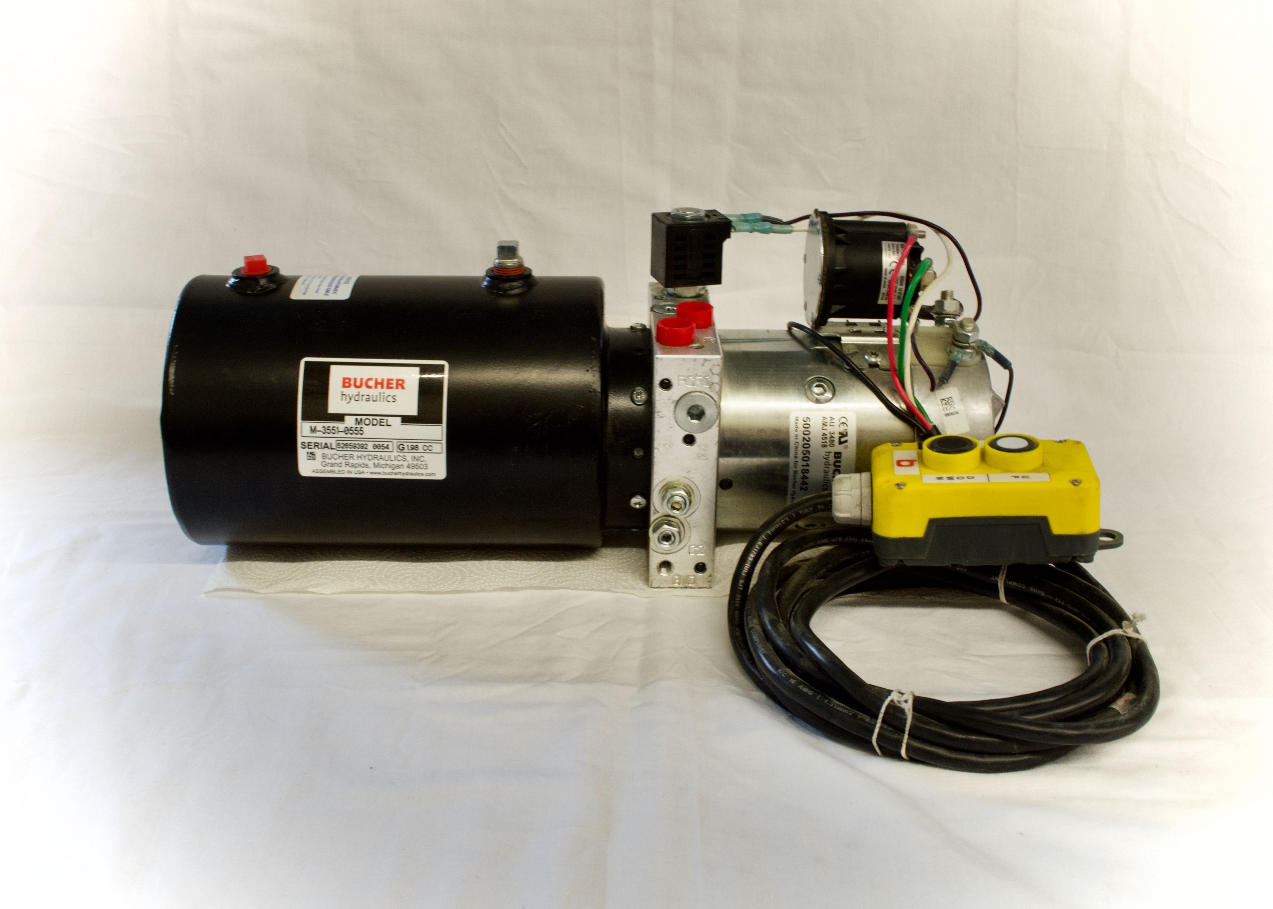
Hydraulic power units (sometimes referred to as a hydraulic power pack) is a self-contained system that generally includes a motor, a fluid reservoir, and a pump. It works to apply the hydraulic pressure needed to drive motors, cylinders, and other complementary parts of a given hydraulic system.
A hydraulic system employs enclosed fluid to transfer energy from one source to another, and subsequently create rotary motion, linear motion, or force. The power unit/pack provide the power needed for this transfer of fluid.
Unlike standard pumps, hydraulic power units use multi-stage pressurization networks to move fluid, and they often incorporate temperature control devices. The mechanical characteristics and specifications of a hydraulic power unit dictate the type of projects for which it can be effective.
Some of the important factors that influence a hydraulic power unit’s performance are pressure limits, power capacity, and reservoir volume. In addition, its physical characteristics, including size, power supply, and pumping strength are also significant considerations. To better understand the operating principles and design features in a hydraulic power unit, it may be helpful to look at the basic components of a standard model used in industrial hydraulic systems.
A large, durable hydraulic power unit built for functioning under a range of environmental conditions will have numerous design characteristics distinct from a typical pumping system. Some of the standard design features include:
Accumulators: These are containers that can be attached to the hydraulic actuators. They collect water from the pumping mechanism and are intended to build and maintain fluid pressure to supplement the motor pumping system.
Motor Pumps: A hydraulic power unit can be equipped with a single motor pump, or multiple devices each with their own accumulator valve. With a multiple pump system, usually only one operates at a time.
Filters: A filter is typically installed along the top of the tank. It is a self-contained bypass unit, with its own motor, pump, and filtering apparatus. It can be used to fill or empty the tank by activating a multi-directional valve. Because they are self-contained, filters can often be replaced while the power unit is functioning.
Power Unit Controllers: The hydraulic controller unit is the operator interface containing power switches, displays, and monitoring features. It is necessary for installing and integrating a power unit into a hydraulic systems, and can usually be found wired into the power unit.
The power source, or prime mover, associated with most hydraulic power units is the motor, which is generally selected based on its speed, torque level, and power capacity. A motor whose size and capabilities complement those of the hydraulic power unit can minimize wasted energy and raise cost-efficiency in the long-term.
The criteria for motor selection vary according to the type of power source being employed. For example, an electric motor has an initial torque much greater than its operating torque, but diesel and gasoline-powered motors have a more even torque-to-speed curve, delivering a relatively steady amount of torque at both high and low running speeds. Consequently, an internal combustion engine may be able to initiate a loaded pump, but not provide enough power to bring it to operating speed if it is not properly matched with the hydraulic power unit.
As a rule of thumb, the power rating for a diesel or gasoline motor used with a hydraulic power unit needs to be at least double that of an electric motor suitable for the same system. However, the cost of the electricity consumed by an electric motor over its operational lifespan usually outstrips the cost of the motor itself, making it important to find an appropriately sized unit that will not waste energy consumption. If the pumping pressure and liquid flow are set at a constant rate, motor size can be measured according to the following parameters:
In some cases, the hydraulic system may require different levels of pressure at various stages of the pumping process, meaning that horsepower can be calculated as the root mean square (rms) and a smaller motor may suffice for the project. However, the motor must still be able to meet the torque requirement for the highest pressure level in the cycle. Once the rms and the maximum torque (including initial and operational levels) have been calculated, they can be cross-referenced with a motor manufacturer’s performance charts to determine whether the motor is the necessary size.
Internal combustion motors have a significantly different torque-to-speed curve with fewer torque fluctuations. Generally, diesel and gasoline motors have to operate at higher speeds to achieve the necessary torque to power a pump. A horsepower rating approximately two and a half times greater than that of an electric motor counterpart is typically required for an internal combustion engine to reach the torque levels needed for a hydraulic power unit. Manufacturers normally recommend that gasoline or diesel motors operate continuously at only a portion of their maximum rated power in order to prolong the motor’s lifespan, and keeping the torque below maximum level can often improve fuel efficiency.
When a hydraulic power unit begins functioning, the gear pump pulls hydraulic fluid out of the tank and moves it into an accumulator. This process continues until the pressure within the accumulator reaches a predetermined level, at which point a charging valve switches the pumping action to begin circulating fluid. This causes the pump to release fluid through a charging valve back into the tank at minimal pressure. A special one-way valve keeps fluid from flowing out of the accumulator, but if the pressure drops by a significant amount, the charging valve reactivates and the accumulator is refilled with fluid. Farther down the line, a reduced-pressure valve regulates the flow of oil moving to the actuators.
If the accumulator is equipped with a fast-stroking device, it can be connected to other accumulators to allow them to charge pressure as well. Often, an automatic thermostat or fan will be included to help alleviate rising temperatures. If the fluid in the system begins to overheat, a temperature switch can shut the motor-pump off, which can also help refill the tank if its fluid level is too low. If the hydraulic power unit has multiple motor pumps, a flow switch can have them alternate in case of reduced fluid supply. Pressure switches can be used to regulate accumulator pressure and a monitoring system can alert operators when pressure has dropped too low, elevating the risk of power unit failure.

The number of components in any hydraulic power unit may vary depending on the complexity of the system. Normally, all these depend on the specific applications of the power unit.
I will make the entire discussion simple and easy to understand. This is because you need to evaluate every component before buying the hydraulic power unit.
In a hydraulic circuit, electric motors convert the electrical energy into a rotational force that drives the pump gear. You’ll learn more about pump gears in section 3.2 of this chapter.
The electrical DC motors convert direct current into a rotational mechanical energy. These motors use a direct power supply whose voltage may vary from DC12V, DC24V, DC48V or DC96V; depending on the design specification of the hydraulic power pack system.
These motors are common in most micro or mini hydraulic power packs. This is because the DC power supply is portable thus, a perfect choice for mobile of portable hydraulic equipment.
For large DC motors that are commonly found in large hydraulic systems, the electric motor manufacturers use electromagnet instead of permanent magnets.
The complexity of the design will depend on the type load the motor should drive. In the case of the hydraulic power packs, we have a hydraulic pump as the load.
In the recent past, a number of hydraulic power pack manufacturers have adopted the permanent magnet and brushless DC motors for most pump applications. The brushed wound field DC motors are still common in some hydraulic applications.
Quite a number of AC hydraulic power packs use induction motors. The most common types of induction motors are:Three phase induction AC motors – requires three power phases
A hydraulic pump is a device that converts the mechanical energy from the motor (rotary motion) into a hydraulic energy. The output shaft from the electric motor is coupled to the shaft of the hydraulic pump.
As the pump rotates, it creates a pressure difference between its inlet and outlet. This pressure difference helps the pump to draw hydraulic fluid from the tank.
It then pushes the hydraulic fluid through the tubes/pipes to the hydraulic cylinder parts or hydraulic motor. In this section, I will focus on the following types of hydraulic pumps:Gear pumps
As you’ll realize in sections 3.2.1, 3.2.2 and 3.2.3, this classification is based on the structural design of these pumps. In each category, I will:Explain the working principle of the pump
As the gears rotate, they create a suction effect at the pump’s inlet and the fluid is drawn into the pump chamber. The rotation directs the hydraulic fluid between the teeth of the gears and the walls of the pump and finally to the output.
In most cases, it is one shaft of the gear that is coupled to the electric motor. Thus, the movement of the second gear (driven gear) occurs as the other gear (driving gear) engages it when the pump is operating.
The herringbone and helical gears in these hydraulic pumps offer a smooth flow than spur gears. The flow rate of these gears is determined by a number of features such as:Size of volume between the gear teeth
These hydraulic pumps have an externally-cut teeth that are contained in and meshed another gear that has an internally-cut teeth. Liquid is drawn when the gears come out of mesh and is discharged when the gears mesh together.
These pumps use their contracting and expanding cavities to move hydraulic fluids from the cylinder to the tubes. This is possible with the help of an electric motor that creates motion, pistons and check valves.
Hydraulic pistons undergo a reciprocating motion (moving up and down or back and forth), thereby building a pressure that forces the fluid through the tubes.
It has a cylindrical block with pistons that move in the direction of its centerline. They have simple designs and guarantee reliable operation.Radial Piston Pump
Its pistons are attached to cylindrical block, forming a wheel like structure. The rotation of the cylindrical block causes a back and forth motion within the pump.
This fluid flows into the hydraulic vane pump chambers. The volume of the vane chambers at the inlet sections is larger than that at the outlet section of the pump.
These pumps can be classified further as either unbalanced or balanced vane pumps. Most opt for the balanced vane pumps because they have better speed ratings, high pressure and increased bearing lifetime.Variable displacement vane pumps
Like other hydraulic pumps, the vane pumps may not be suitable for certain pumping applications. Here are the main advantages and disadvantages of these pumps.
Type of materials for these main sections:Shaft seal – Component mechanical seals, industry-standard cartridge mechanical seals, and magnetic-driven pumps.
With these two main components of the hydraulic power pack (electric motor and pump), your systems should draw the hydraulic fluid, ready to supply it to the circuit.
A hydraulic manifold helps to regulate the fluid flow, pressure and flow direction in hydraulic systems. It acts a junction between the hydraulic pump and hydraulic actuators.
The hydraulic manifold design may vary depending on the types and number of control components. With the help of various hydraulic manifold valves, you can easily monitor and control the fluid flow.
As you’ll realize later in this section, these hydraulic manifold blocks mainly vary depending on how hydraulic valves are interconnected to each other.
The hydraulic central manifold has several multiple options you can use for integral solenoid, mechanical operated hydraulic valves and an interface for custom designed valves.
For more complex and flexible functionalities, you can use the hydraulic stacked manifold. This helps to combine multiple functions into one assembly such as reducing the possibility of pressure drop.
This is actually the main reason why you should consider a stacked manifold block as an extra section of the hydraulic center block. You can use it when the space in the central manifold cannot hold more valves or large size cartridge valves.
Target has delivered thousands hydraulic power units for different applications around the world. These include a series of standard hydraulic manifolds that are commonly used in most hydraulic power packs.
At times, the standard hydraulic power packs may not meet the specific requirements of your applications. In such cases, you should opt for customized hydraulic manifold blocks that meet your specific requirements
Apart from the hydraulic manifold blocks, I need to introduce you to the actual components that control the hydraulic fluid. This is the hydraulic valves.
Valves are devices that control the flow of fluids in hydraulic systems. They regulate flow by cutting-off, diverting, providing an overflow relief and preventing reverse flow of the hydraulic fluid, among other functions.
There are very many hydraulics valves available in the market. However, for the scope of this eBook, I will focus on the following:Hydraulic check valves
As you can see, there are many types of hydraulic cartridge valves available in the market. These valves are suitable for high flow rates and leak free control systems such as hydraulic power packs.
A hydraulic check valve allows fluid to flow through it in one direction, i.e. it prevents a reverse flow. For this reason, it is also referred to as one-way valve or non-return valve.
Since the check valves provide unidirectional flow, thereby providing a sealing against the reverse flow, it is advisable that you install them on the outlet side of the hydraulic pump. Below, is an image showing how a hydraulic check ball valve functions:
In hydraulic power pack circuits, you’ll mount the internal check valve in the block, while the external check valve on mounting hole found on the surface of the valve block.
At times, hydraulic power pack manufacturing companies may include a pilot operated check valve. You can control these valves using fluids from other valves.
A hydraulic pilot-operated check valve is unique in the sense that; they allow hydraulic fluid to flow in one direction, but, you can still disable them using a pilot pressure.
In hydraulic circuits, relief valves protect the downstream circuits from over pressurization. They are a good example of a safety valve and you may also refer to them as pressure relief valves (PRV).
During the period of work cycles, these pilot operated relief valves unload the pump at low pressure. Another important classification criteria is the type of material.
A number of adjustable hydraulic pressure relief valves are manufactured from zinc plated carbon steel bodies. They have hardened stainless steel sealing components.
You’ll find that when the pressure is reduced within 25% of the set point, the valve will automatically reseal. Below is the actual image of a hydraulic relief valve:
Below are seven crucial parameters you need to consider when buying a pressure valve:Pressure rating; it should be compatible with your hydraulic power pack system pressure.
In most applications, a hydraulic release valve also means a 2 way 2 position hydraulic cartridge solenoid valve. Solenoid valves are electromechanical operated valves.
Such valves have a fast and a safe switching mechanism. They are also: reliable, durable, compact in design and offer low control power. Below are examples of hydraulic release valves:
It’s the electric current that makes it a two-way valve. Where, it will allow the hydraulic fluid to return to the tank, thereby, releasing the load of the cylinder.
Owing to the varying circuit designs of directional control valves, you’ll find quite a number of hydraulic control valves and valve block mounting dimensions.
Normally, you can adjust hydraulic solenoid valve depending on the type of control mechanism of a specific application. Moreover, the complexity of a directional control valve will also depend on the specific hydraulic system you intend to control.
In most hydraulic circuits, you can install them near delicate gauges that may get damaged in case of a sudden pressure surge. Also, you can use these throttle valves in the pipes returning oil back to the tank.
Needle valves can handle a wide range of pressures. Depending on the nature of the hydraulic fluid system, a needle valve can handle the pressures that range from 5,000 to 6,000 psi.
Some of the most common materials include carbon steel, stainless steel or brass. Each material has unique physical and chemical properties making them suitable for specific hydraulic applications.
The complexity of the design will depend on the specific application of the directional valve in a hydraulic control circuit. In hydraulic circuits, the directional control valve symbol is:
Modular valves provide a wide range of mounting options in hydraulic circuits. They have a number of mounting holes, valves and loops compared to cartridge valves.
You can fit them in any system to fulfill the specific hydraulic circuit requirements. At the moment, there is a wide range of modular valves available in the market such as pilot operated check valves, flow control valves, pressure reducing valves and counterbalance valves.
The hydraulic flow valves are available in a wide range of configurations and designs, depending on the functional purposes of each valve. A good example is a modular flow control valve with a directional control valve and a sub plate.
As you can see, there are very many types of modular valves. Therefore, you need to review the manufacturer’s data sheet to choose a modular design that best suits your hydraulic system.
Throughout this section, I believe you have noted that there are very many types of hydraulic valves. Always choose one that best suits your hydraulic power pack.
Remember, with an appropriate valve, you can have full control of the fluid flowing through the hydraulic pipes. Now, let’s discuss the next component of a hydraulic power pack.
A hydraulic tank is a container that holds the fluid that you’ll supply to the system to do the work. At times, you may refer to it as a hydraulic reservoir.
Hydraulic oil tanks for power pack units come in a wide range of shapes, sizes and materials. For the scope of this eBook, I will focus on the following:Hydraulic plastic tanks
Quite a number of hydraulic plastic tanks are made from polypropylene (PP). This is a special oil tank material that is resistant to corrosion, low temperature, high temperature, acid-alkaline solutions and solar radiation.
Most manufacturers use an injection molding technique that results in a light weight and strong hydraulic fluid tank. The tank can withstand high pressure and resistant to diverse weather conditions.
The size may vary depending on both design and size of the hydraulic power pack. The volume of the tank should be large enough to allow for all hydraulic fluids in the pipes to drain in the tank.
Therefore, you’ll find that the hydraulic fuel tank size may vary depending on the hydraulic equipment such as hydraulic stacker, hydraulic lifting equipment, hydraulic dock ramp, hydraulic scissor lift, etc.
Like the plastic hydraulic reservoir tanks, the hydraulic steel tanks are available in a wide range of sizes and designs. Unfortunately, for these hydraulic power pack steel tanks, you’ll need a liquid meter to determine the level of hydraulic fluid.
Basically, these tanks are specifically manufactured to resist high and low temperature conditions. They ensure the properties of hydraulic fluid remains the same at all times.
This allows air to get into the tank, thereby protecting the tank from atmospheric pressure. Remember, as the gear pump rotates it creates a vacuum that forces hydraulic fluid into it.
You will mount hydraulic power pack to the other customized steel tank through the steel tank neck. So, you can mount one or two or more power packs on one steel, square customized steel tank.
A coupling is the main device you’ll use to connect your electric motor and hydraulic pump. That is, you’ll connect the shaft of your motor to that of the hydraulic pump.
The type of coupling will depend on the position of your electric motor relative to that of the hydraulic pump. Some of the most common types of coupling include:Flexible coupling; this is when the coupling can handle both parallel and angular misalignment.
To ensure there is a seamless flow of hydraulic fluid from the tank to the cylinder, you’ll need the following:Fittings; this connects the hose to the outlet of the manifold if they don’t match.
Hydraulic pipes and filters play an integral role in hydraulic power pack systems. In this sub-section, you’re going to learn about:Hydraulic suction pipe
As the hydraulic pump rotates, it creates a pressure difference, hence, the fluid flows to the pump. A hydraulic suction pipe is the pipe that connects the tank and the pump.
Hydraulic filters remove debris or impurities in the oil before it is suctioned through the hydraulic pipe to the pump. It helps to keep the hydraulic system clean.
These filters come in different sizes and configurations with some equipped with magnet to remove metallic parts from the hydraulic fluid. This prevents clogging.
These are basic components of hydraulic power packs that depend on electrical signals to send commands to the system. In this subsection, you’ll learn about three major components:Cable remote-push button pendant
Commonly used for single / double acting hydraulic system. There was a key you can lock this remote away from battery, so, nobody can operating power pack without this key. It has four wires, which are 4 meters4 buttons Remote
A hydraulic actuator is the mechanical portion that converts hydraulic power into useful mechanical work. This mechanical work can either be linear motion, rotary motion or oscillatory motion.
A valve actuator refers to the mechanism of opening and closing a valve. Some of the most common types of valve actuators include manual, pneumatic, hydraulic, electric and spring valve actuators.
Linear actuators create motion in a straight line. You can create motion using different mechanisms that may involve the use of mechanical, hydraulic, pneumatic, piezoelectric or electro-mechanical actuators.
The electro-hydraulic actuators are commonly used in applications that require a high degree of precision. They have self-contained actuators, which are operated only by electric power.
In chapter 1, section 1.2 (sorts of hydraulic power pack) and section 1.3 (function of hydraulic power), I did discuss all the vital aspects about single acting and double acting hydraulic cylinders.
Just as a reminder, you should know that hydraulic cylinder is an important hydraulic actuator. It converts hydraulic energy into a mechanical energy we use to perform a number of tasks.
As you have learnt earlier, hydraulic power packs are broadly categorized as either single acting hydraulic cylinder or double acting hydraulic cylinder. So, this fact does not change in hydraulic cylinder actuators.
A position-sensing hydraulic cylinder is used in more advanced systems where it provides an instantaneous analog or digital electronic position feedback information. That is, it indicates the extent of rod extension during any stroke.
As you have seen earlier (chapter 1), all these hydraulic power packs have their unique advantages and disadvantages. You will learn more about this in chapter 5.
That is, a hydraulic motor can generate different magnitude of torque at different pressures. Some of the main applications include hydraulic bicycle and hydraulic hybrid vehicle.
Before it begins to rotate, the hydraulic fluid should provide sufficient torque to turn the motor. The torque that the hydraulic fluid provides can be categorized as:
This is the minimum torque you’ll need to start the motor at no load. That is, the hydraulic energy should overcome the internal frictional forces of the motor.
The existing hydraulic motors may be classified into four different categories. These include:Hydraulic gear motors; they include hydraulic and epicyclic gear motors.
The truth is, hydraulic pumps add more energy to the circuit by pushing the fluid while the hydraulic motors act as actuators that change hydraulic energy into rotary motion. Furthermore, hydraulic pumps are coupled to an electric motor.
The concept of hydrostatic transmission is based on the fact that, whenever a pump is connected to a prime mover, it generates fluid flow that drives a hydraulic motor. It is this hydraulic motor that is connected to the load.
To make it more versatile, you can make either the pump or motor variable displacement. You can learn more about this concept here: Understanding Hydrostatic Transmissions.
This is breaking mechanism that uses brake fluid (hydraulic fluid) to stop or control a moving wheel or object. You can review hydraulic power pack applications in chapter one to learn more about this.
Hydraulic fluid is the medium through which power or energy is transferred in hydraulic systems. Some of the most commonly used hydraulic fluids are either mineral or water based solutions.
Basically, these are the basic aspect you need to know about hydraulic fluid. To learn more about these oils then you can click: Engineering Essentials: Hydraulic Fluids.
Our business puts emphasis over the administration, the introduction of talented staff, plus the construction of employees building, striving hard to boost the standard and liability consciousness of staff members. Our corporation successfully attained IS9001 Certification and European CE Certification of Hydraulic Valve Block, Mini Dc Motor Power Unit, 24v Dc Hydraulic Pump Power Unit, We persistently develop our enterprise spirit "quality lives the business, credit score assures cooperation and retain the motto inside our minds: consumers very first.
The organization keeps for the procedure concept “scientific administration, superior quality and effectiveness primacy, shopper supreme for 18 Years Factory Omh Mh Bmh 155 Rpm Orbit Hydraulic Motor 20 Hp For Putzmeister, Each of the time, we have been paying focus on all facts to insure each product or service happy by our clients.
The organization keeps for the procedure concept “scientific administration, superior quality and effectiveness primacy, shopper supreme for Hydraulic Parts, Omh Motor, Orbit Motor, We integrate all our advantages to continuously innovate, improve and optimize our industrial structure and product performance. We are going to always believe in and work on it. Welcome to join us to promote green light, together we will make a better Future!
Cycloidal gear motors convert hydraulic energy (pressure, oil flow) into mechanical energy (torque, speed). Cycloidal gear motors operate on the principle of an internal gear (rotor) rotating within a fixed external gear (stator). The internal gear transmits the torque generated by the application of pressure from hydraulic oil fed into moto which is then delivered via the motor’s output shaft. Cycloidal gear motors have high starting torque and constant output torque at wide speed range.
With this motto in mind, we"ve come to be one of quite possibly the most technologically innovative, cost-efficient, and price-competitive manufacturers for Factory Free sample Dock Leveler Power Pack - 18 Years Factory Omh Mh Bmh 155 Rpm Orbit Hydraulic Motor 20 Hp For Putzmeister – Guorui, The product will supply to all over the world, such as: Panama, America, Victoria, They are sturdy modeling and promoting effectively all over the world. Never ever disappearing major functions within a quick time, it"s a have to in your case of fantastic good quality. Guided by the principle of "Prudence, Efficiency, Union and Innovation. the corporation. ake an excellent efforts to expand its international trade, raise its organization. rofit and raise its export scale. We have been confident that we"ve been going to have a bright prospect and to be distributed all over the world in the years to come.

Check that the pump shaft is rotating. Even though coupling guards and C-face mounts can make this difficult to confirm, it is important to establish if your pump shaft is rotating. If it isn’t, this could be an indication of a more severe issue, and this should be investigated immediately.
Check the oil level. This one tends to be the more obvious check, as it is often one of the only factors inspected before the pump is changed. The oil level should be three inches above the pump suction. Otherwise, a vortex can form in the reservoir, allowing air into the pump.
What does the pump sound like when it is operating normally? Vane pumps generally are quieter than piston and gear pumps. If the pump has a high-pitched whining sound, it most likely is cavitating. If it has a knocking sound, like marbles rattling around, then aeration is the likely cause.
Cavitation is the formation and collapse of air cavities in the liquid. When the pump cannot get the total volume of oil it needs, cavitation occurs. Hydraulic oil contains approximately nine percent dissolved air. When the pump does not receive adequate oil volume at its suction port, high vacuum pressure occurs.
This dissolved air is pulled out of the oil on the suction side and then collapses or implodes on the pressure side. The implosions produce a very steady, high-pitched sound. As the air bubbles collapse, the inside of the pump is damaged.
While cavitation is a devastating development, with proper preventative maintenance practices and a quality monitoring system, early detection and deterrence remain attainable goals. UE System’s UltraTrak 850S CD pump cavitation sensor is a Smart Analog Sensor designed and optimized to detect cavitation on pumps earlier by measuring the ultrasound produced as cavitation starts to develop early-onset bubbles in the pump. By continuously monitoring the impact caused by cavitation, the system provides a simple, single value to trend and alert when cavitation is occurring.
The oil viscosity is too high. Low oil temperature increases the oil viscosity, making it harder for the oil to reach the pump. Most hydraulic systems should not be started with the oil any colder than 40°F and should not be put under load until the oil is at least 70°F.
Many reservoirs do not have heaters, particularly in the South. Even when heaters are available, they are often disconnected. While the damage may not be immediate, if a pump is continually started up when the oil is too cold, the pump will fail prematurely.
The suction filter or strainer is contaminated. A strainer is typically 74 or 149 microns in size and is used to keep “large” particles out of the pump. The strainer may be located inside or outside the reservoir. Strainers located inside the reservoir are out of sight and out of mind. Many times, maintenance personnel are not even aware that there is a strainer in the reservoir.
The suction strainer should be removed from the line or reservoir and cleaned a minimum of once a year. Years ago, a plant sought out help to troubleshoot a system that had already had five pumps changed within a single week. Upon closer inspection, it was discovered that the breather cap was missing, allowing dirty air to flow directly into the reservoir.
A check of the hydraulic schematic showed a strainer in the suction line inside the tank. When the strainer was removed, a shop rag was found wrapped around the screen mesh. Apparently, someone had used the rag to plug the breather cap opening, and it had then fallen into the tank. Contamination can come from a variety of different sources, so it pays to be vigilant and responsible with our practices and reliability measures.
The electric motor is driving the hydraulic pump at a speed that is higher than the pump’s rating. All pumps have a recommended maximum drive speed. If the speed is too high, a higher volume of oil will be needed at the suction port.
Due to the size of the suction port, adequate oil cannot fill the suction cavity in the pump, resulting in cavitation. Although this rarely happens, some pumps are rated at a maximum drive speed of 1,200 revolutions per minute (RPM), while others have a maximum speed of 3,600 RPM. The drive speed should be checked any time a pump is replaced with a different brand or model.
Every one of these devastating causes of cavitation threatens to cause major, irreversible damage to your equipment. Therefore, it’s not only critical to have proper, proactive practices in place, but also a monitoring system that can continuously protect your valuable assets, such as UE System’s UltraTrak 850S CD pump cavitation senor. These sensors regularly monitor the health of your pumps and alert you immediately if cavitation symptoms are present, allowing you to take corrective action before it’s too late.
Aeration is sometimes known as pseudo cavitation because air is entering the pump suction cavity. However, the causes of aeration are entirely different than that of cavitation. While cavitation pulls air out of the oil, aeration is the result of outside air entering the pump’s suction line.
Several factors can cause aeration, including an air leak in the suction line. This could be in the form of a loose connection, a cracked line, or an improper fitting seal. One method of finding the leak is to squirt oil around the suction line fittings. The fluid will be momentarily drawn into the suction line, and the knocking sound inside the pump will stop for a short period of time once the airflow path is found.
A bad shaft seal can also cause aeration if the system is supplied by one or more fixed displacement pumps. Oil that bypasses inside a fixed displacement pump is ported back to the suction port. If the shaft seal is worn or damaged, air can flow through the seal and i


 8613371530291