
spline hydraulic pump free sample

Get high-performing and premium quality Gear Pumps 9 Tooth Spline Shaft for your hydraulic pump. This equipment plays a critical role in transforming mechanical energy into hydraulic power and helps in operating industrial and commercial hydraulic systems.
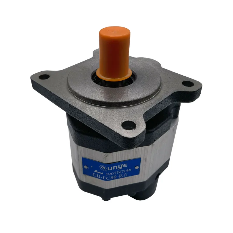
Our excellent quality hydraulic gear pump 9 tooth is reliable equipment with high efficiency providing smooth and continuous flow. We have standard gear pumps from the leading manufacturer. Explore our range of gear pumps 9 tooth spline shaft available in the following options:
Additionally, we have a similar hydraulic 9 tooth spline shaft in CCW configuration featured on our online store. At Magister Hydraulics, we have European manufactured hydraulic equipment and parts manufactured according to OEM standards. Plus, all our products undergo strict quality control to ensure the highest quality and give you maximum value for your money.

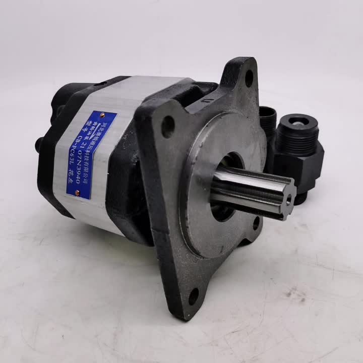
0.27 CID Cast iron hydraulic gear pump 3600 PSI max presure. Durable 9 tooth spline shaft with counter-clockwise (left) rotation. SAE A – 2 bolts mounting flange and 4000 max RPM. 1-year warranty and free same day ground Continental US shipping. Magister gear pumps are great replacements for a variety of farming and material handling equipment.
Rear port kits allow Dynamic to convert a standard side ported gear pump into a rear ported pump on demand. To purchase a rear ported pump, simply add "-BB" to the end of your part number and we"ll take care of the assembly for you.
Rear port kits are also available for purchase separately to distributors with the ability and equipment to perform conversions at their facility. Please note, disassembly and conversion of the pump will void the manufacturer"s warranty if done by anyone other than Dynamic Fluid Components.

Whether gear, vane, or piston pump, there may come a time when you have to replace your hydraulic pump. When your equipment isn’t working properly and you have narrowed the problem down to a hydraulic pump that needs to be replaced, what do you need to know?
The pump may simply be worn out—they do have a natural lifespan, as they are a wearable item in a hydraulic system. Although it is not possible to give an average lifespan given the different types of pumps and widely varying hours of operation; in general, you can expect many years of good operation from a hydraulic pump in most truck-mounted hydraulic systems. However, the life of a hydraulic pump might be much longer than what you are experiencing. Here are some questions you should ask:
Has the equipment been operating acceptably with this pump for a number of years without incident, and has the decline in performance been gradual over a longer period of time?
In this case, you’ll need to get the pump make and model number so that you can make sure that your replacement will be correct—either with an exact replacement or with another make that has the same operating specifications.
In any case, when replacing a failed hydraulic pump you will want to make sure to use this opportunity to also change out your hydraulic fluid (or at the very least use a filter cart and filter your oil). In the process of failing, your pump has introduced contaminants into your hydraulic system that you want to remove before they damage your new pump or any other hydraulic component. You will want to change your filter element(s) when you install your new pump, and then change it (them) out after a break-in period on your new pump.
If not, then let’s make sure there is not something else going on, or you may just find yourself replacing pumps frequently because the underlying problem hasn’t been addressed.
Input shaft is twisted/bcanroken: This occurs due to an extreme shock load to the pump. Typically, this happens when a relief valve is missing from the system, not functioning correctly, set to a much higher value than what the pump can withstand, or is too small for the system flow and thus cannot function correctly.
Shaft fretting:Fretting corrosion occurs under load in the presence of repeated relative surface motion, for example by vibration. Direct mount pump splines can be worn away. The solutions include:
Using larger pump and PTO shafts will not eliminate fretting, but may resolve the problem because of the increased metal available before the failure occurs.
Make sure that the pump is able to get a good flow of oil from the reservoir—pumps are designed to have the oil feed pushed to the pump by gravity and atmospheric pressure, not by “sucking” oil. If the oil level in the reservoir is lower than the inlet of the pump, or the run too long or uphill, oil may not flow adequately to the pump. You can check if the pump is receiving oil adequately by using a vacuum gauge at the pump inlet. For a standard gear pump, at maximum operating RPM, the gauge should read a maximum of 5 inches HG. Larger numbers will damage a gear pump, and if you have a piston pump, the maximum number will be lower for good pump life.
Over pressurization: Pressure relief settings may have been adjusted or changed, and are now higher than what the pump can withstand without causing damage.
Pumps don’t produce pressure, they produce flow and are built to withstand pressure. When the system pressure exceeds the pump design, failure begins—either gradually or catastrophically.
When installing the new pump, back all the relief settings off. Then with the use of a pressure gauge T’d in at the pump outlet, gradually adjust the pressure relief setting until a cylinder or motor begins to move. Once the cylinder has reached the end of its stroke, gradually increase the pressure relief setting until reaching the max system pressure (which would be the pressure rating of the lowest rated component in the system). Sometimes, if a pump has been replaced and is larger than the original (produces more flow), the relief may not be able to allow all the flow being produced to escape back to tank. When that happens, the relief valve is “saturated” and the effect is the same as having no relief in the system. Pressures can reach levels much higher than the relief settings and components can be damaged or destroyed.
Contamination: Over time, the system oil has gotten dirty or contaminated and no longer is able to lubricate the pump, or is carrying contamination to the pump.

Splines are ridges or teethdrive shaft that matches with grooves in a mating piece and transfer torque to it, maintaining the angular correspondence between them.
For instance, a gear mounted on a shaft might use a male spline on the shaft that matches the female spline on the gear. Adjacent images in the section below show a transmission input shaft with male splines and a clutch plate with mating female splines in the center hub, where the smooth tip of the axle would be supported in a pilot bearing in the flywheel (not pictured). An alternative to splines is a keyway and key, though splines provide a longer fatigue life, and can carry significantly greater torques for the size.
where the grooves of the inner and outer parts are formed as linear races filled with ball bearings to allow for free linear motion even under high torque. To allow longer travel the outer spline can incorporate channels to re-circulate the balls, in this way torque can be transferred from a long shaft while travelling up or down the length.
Drive shafts on vehicles and power take-offs use splines to transmit torque and rotation and allow for changes in length. Splines are ubiquitous in aerospace, due to the spline"s higher reliability and fatigue life compared to keyed shafts.
Splines are used in several places in bicycles. The crank arm to BB shaft interfaces that are splined include ISIS Drive, Truvativ GXP and Howitzer, Shimano"s Octalink and many others, most of which are proprietary. Some cranksets feature modular spiders, where torque is transmitted through splines. Cassettes engage the freehub via a spline that has one groove wider than the others to enforce a fixed orientation. Disc brake mounting interfaces that are splined include Centerlock, by Shimano.
Aircraft engines may have a spline upon which mounts the propeller. There may be a master spline which is wider than the others, so that the propeller may go on at only one orientation, to maintain dynamic balance. This arrangement is commonly found in larger engines, whereas smaller engines typically use a pattern of threaded fasteners instead.
There are two complementary types of splines, internal and external. External splines may be broached, shaped (for example on a gear shaping machine), milled, hobbed, rolled, ground or extruded. There are fewer methods available for manufacturing internal splines due to accessibility restrictions. Methods include those listed above with the exception of hobbing (no access). Often, with internal splines, the splined portion of the part may not have a through-hole, which precludes use of a pull / push broach or extrusion-type method. Also, if the part is small it may be difficult to fit a milling or grinding tool into the area where the splines are machined.
To prevent stress concentrations the ends of the splines are chamfered (as opposed to an abrupt vertical end). Such stress concentrations are a primary cause of failure in poorly designed splines.
Dan Seger (January 2005). "Inside Splines". Gear Solutions Magazine. Retrieved 2010-07-06. The externally splined shaft mates with an internal spline that has slots, or spaces, formed in the reverse of the shaft"s teeth.
1966 G. W. MICHALEC Precision Gearing vii. 324 Generally, involute internal and external teeth are mated, but non~involute splines are also suitable. 1979 Industrial Fasteners Handbk. I. 318 There are two basic forms of spline--straight-sided splines which may number 4, 6, 10 or up to 16 splines equally distributed around the circumference of a shaft, and serrated splines which are in the form of adjacent triangular teeth.
At OneHydraulics, we aim for 100% customer satisfaction on every order. If you are not completely satisfied with your order, please contact us right away so we can make it right.
Items purchased on onehydraulics.comwith inventory from our Houstonlocation can be returned within 30 days from the date it was shipped. Items purchased that come from our manufacturer"s stock may be subject to restocking fees as determined by our manufacturers. Before returning any products, please verify with OneHydraulics if a restock fee is required for the product return.
Any item custom manufactured for a customer’s application,including winches and other made-to-order products, may be non-cancellable and non-returnable. OneHydraulics will not accept returns on those items for any reason. If you may need to return a product you are ordering, please verify if it may be returned prior to ordering.
All items must be returned in NEW condition, in the original packaging. We will not accept items that have been used or purchased from another company. All returns are subject to a restocking fee and shipping fees are non-refundable. If a return is required as a result of an error made by OneHydraulics (e.g., shipping an incorrect item, etc.), the abovementioned fees may not apply. Please contact your sales person or emailsales@onehydraulics.comso we can fix any errors relating to your order immediately.
Please see our Terms and Conditions relating to warranty claims. Prior to shipping an item back to OneHydraulics, you must first obtain a Return Goods Authorization (RGA) form and number. All returns must be shipped prepaid, with the RGA number clearly marked on the outside of the shipping carton. All items must be packaged properly to prevent damage upon shipping back to OneHydraulics. Failure to do so may result in a rejection of the return. Following our inspection, you will be notified of the product’s disposition and charges, if any. Products returned for factory warranty issues must be accompanied by a report explaining the non-performance or failure of the returned part. Please contact OneHydraulics prior to shipping back any item relating to a warranty issue, as those items may need to ship back to the factory directly.
Any item labeled ‘Final Sale’ on the website is non-cancellable and non-returnable. Any item custom manufactured for a customer’s application is non-cancellable and non-returnable. OneHydraulics will not accept returns on those items for any reason.

Although a splined shaft looks like having a series of shaft keyways with keys pushed in, splines are considerably stronger than the keyed joint as the keyways weaken the shaft and reduce its torque-carrying capacity.
Although they look like gears, Splines only transmit torque and rotation on the same axis. They are used mainly for the following reasons.Mechanical transmission elements such as gears and pulleys might need to be removed from the shaft due to design for manufacture and assembly (DFMA), ie during assembly or to aid manufacturing.
A good spline joint provides very high secure torque transmission, little clearance, minimum backlash, good centring between the coupled components, low noise, low wear and small or no axial forces.
The term “spline” provides an umbrella term for all profiles, and the splines can be divided into the following three groups based on their flank form.Parallel-sided or straight-sided spline
Depending on their relative axial movement, splines and serrations can also be grouped as fixed splines or flexible splines. As the name suggests, a fixed spline is a joint that does not move axially, such as gears, pullers, turbine wheels, etc.
Involute splines are made with pressure angles 30o, 37.5 and 45o and can include between 60 and 100 splines per the American National Standard. Involute splines can be either Side fit or Diameter fit.
The main disadvantages of serrations are due to comparably small teeth, it can only be used for low torque applications. These are only used for non-axial moving applications. Like straight-sided splines, there will be line contact and wear.
During the design of shaft splines and serrations, the following stresses must be considered to evaluate the suitability of the spline joint strength.Spline shaft shear stress
Generally, the shaft diameter is dictated by the overall design, such as bearing arrangements, seals, elements etc. In that instance, the spline strength calculations can be used in two ways.Stress calculation can be used to find the safety factor by calculating the stress involved and comparing it with the allowable stresses as per failure modes.
Spline shaft shear stressSolid shaft stressesHollow shaft stresses\[ S_s = \frac{16T}{\pi{D_{re}}^{3}} \]\[ S_s = \frac{16T{D_{re}}}{\pi ({D_{re}}^4-D_h^4)} \]
Calculated stress using the above equations must not exceed the allowable stress (\[S^a\]) of the spline material and can be shown as follows\[S^a_s \geq S_s \frac{{K_{a}}}{{L_{f}}}\]
The load is equally distributed if the transferring load is purely radial torsion and the torsional radial load is in the middle of the spline length. But if, for example, a bevel gear is used, this will put some unwanted axial loads into the spline.
Misalignment of spline couplings has been recognized as harmful to splines because it causes significant load concentration on spline teeth and accelerates spline wear and fretting fatigue.Load distribution factor for splines KmEffective face width (Fe)
If there are any axial or radial shock loading on the element connected, then care should be taken to support the external axial and radial shock loads to increase the joint life. This should also be considered during the calculations using the spline application factor.
Life factors for splines under wear conditions are based on the number of revolutions of the spline joint, not reversible cycles. Wear life factor only applies to flexible or sliding spline compressive stress calculations, as each time the spline slide back and forth, it wears the teeth.No of revolutions of the splineWear life factor for splines (Lw )10,0004


 8613371530291