
sumitomo hydraulic pump free sample
We can normally fulfill our respected consumers with our great excellent, great value and good provider due to we"re much more specialist and extra hard-working and do it in cost-effective way for Hydraulic Pump Used In Excavator, OEM/ODM Hydraulic Mobile Pump, Hydraulic Pump Repair Parts, We always concertrating on developing new creative product to meet request from our clients all over the world. Join us and let"s make driving safer and funnier together!
ABT Series Servo Pump is high performance servo hydraulic system special oil pump. It is researched and developed together by three party- Ningbo Vicks Hydraulic Co., Ltd. American Albert Fluid Power Co., Ltd. Zhejiang University Mechanical Control Engineering Research Institute. The core components are imported from America. We have the proprietary intellectual property hydraulic systems of rubber and plastic machines, shoes machines, forging and press machines, bending machines and shearing machines.
2.se outside leakage and leakage volume control designation low the oil temperature obviously. Based on the hydraulic components leakage volume, can adjust the oil leakage smartly, the pump pressure pulse is small at high pressure and low speed, the injection finished products will be more higher accuracy.
3.With the coordination of high pressure oil and vice spring structure, can make the pump run normally at low speed, can fit low and high speed shift, high and low pressure speed shift, right and left rotation shift etc working status of servo hydraulic system perfectly.
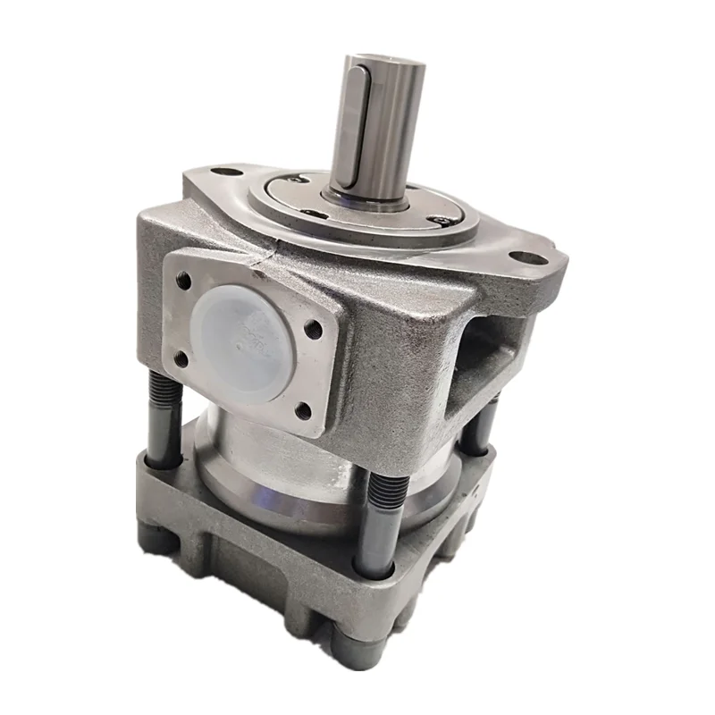
1.Pump housing design with Rc3/8 leaked oil port, the leaking oil must through the port back to oilbox, do not blocking, or will cause the shaft seal damage.
2.Following photos instruction, Leakage of oil pipeline must be upward arrangement, make the sliding bearing in the pump shaft center in the leaked oil dip full lubrication.
● Proper fluid condition is essential for long and satisficatory life of hydraulic components and systems. The filtration rating should not be lower than 25μm. Filter of 70-150μm on the inlet port is recommended and its rated flow should not be lower than 200% of pump’s.
● Horizontal mounting is recommended to maintain necessary case fluid level. Concentricity of shafts between pump and motor is important to pump life and should be within ∅0.1mm. It is better to use flexible coupling to avoid harmful effects.
● The oil pump allows the inhalation vacuum as 110mm column of mercury. Installation should near fuel tank, inhaling the height can not be big in 500mm.
● Please notice the seal of flange at port connections, ports and absorb pipeline has to be sealed strictly, to prevent air leakage. If not it will cause the noise and vibration of system, also will make foam, to low the life of pump.
● Before starting pump, please check up if the inlet and outlet have been correctly connected and the rotation of the pump is inline with the nameplate. (CW without notice).
● When initially starting the pump after long-time unused, removing all trapped air from the system can be accomplished by loosening flange or connections.
● The cartridge design of ABT series servo pumps offers fast and efficient field service ability, when replacing the cartridge, seals inside the pump should be checked to avoid them crimping, when tighting the fastening screws, they should be treated with even force in diagonal direction.
Our purpose is to fulfill our clients by offering golden company, great price and premium quality for Factory Free sample ABT Series Servo Pump Single Hydraulic Pump for Slovenia Importers, The product will supply to all over the world, such as: Angola, Thailand, Irish, We have more than 200 staff including experienced managers, creative designers, sophisticated engineers and skilled workers. Through hard work of all employees for the past 20 years own company grew stronger and stronger. We always apply the "client first" principle. We also always fulfill all contracts to the point and therefore enjoy excellent reputation and trust among our customers. You are very welcome to personally visit our company.We hope to start a business partnership on the basis of mutual benefit and successful development . For more information please do no hesitate to contact us..

We have probably the most state-of-the-art output equipment, experienced and qualified engineers and workers, recognized good quality manage systems plus a friendly skilled income workforce pre/after-sales support for Rule Bait Pump Cartridge, Hydraulic Pump Calculations Pdf, Yuken Hydraulic Gear Pump, sincerity and strength ,always keep approved good quanlity ,welcome to our factoty for visit and instruction and business.
ABT Series Servo Pump is high performance servo hydraulic system special oil pump. It is researched and developed together by three party- Ningbo Vicks Hydraulic Co., Ltd. American Albert Fluid Power Co., Ltd. Zhejiang University Mechanical Control Engineering Research Institute. The core components are imported from America. We have the proprietary intellectual property hydraulic systems of rubber and plastic machines, shoes machines, forging and press machines, bending machines and shearing machines.
2.se outside leakage and leakage volume control designation low the oil temperature obviously. Based on the hydraulic components leakage volume, can adjust the oil leakage smartly, the pump pressure pulse is small at high pressure and low speed, the injection finished products will be more higher accuracy.
3.With the coordination of high pressure oil and vice spring structure, can make the pump run normally at low speed, can fit low and high speed shift, high and low pressure speed shift, right and left rotation shift etc working status of servo hydraulic system perfectly.
1.Pump housing design with Rc3/8 leaked oil port, the leaking oil must through the port back to oilbox, do not blocking, or will cause the shaft seal damage.
2.Following photos instruction, Leakage of oil pipeline must be upward arrangement, make the sliding bearing in the pump shaft center in the leaked oil dip full lubrication.
● Proper fluid condition is essential for long and satisficatory life of hydraulic components and systems. The filtration rating should not be lower than 25μm. Filter of 70-150μm on the inlet port is recommended and its rated flow should not be lower than 200% of pump’s.
● Horizontal mounting is recommended to maintain necessary case fluid level. Concentricity of shafts between pump and motor is important to pump life and should be within ∅0.1mm. It is better to use flexible coupling to avoid harmful effects.
● The oil pump allows the inhalation vacuum as 110mm column of mercury. Installation should near fuel tank, inhaling the height can not be big in 500mm.
● Please notice the seal of flange at port connections, ports and absorb pipeline has to be sealed strictly, to prevent air leakage. If not it will cause the noise and vibration of system, also will make foam, to low the life of pump.
● Before starting pump, please check up if the inlet and outlet have been correctly connected and the rotation of the pump is inline with the nameplate. (CW without notice).
● When initially starting the pump after long-time unused, removing all trapped air from the system can be accomplished by loosening flange or connections.
● The cartridge design of ABT series servo pumps offers fast and efficient field service ability, when replacing the cartridge, seals inside the pump should be checked to avoid them crimping, when tighting the fastening screws, they should be treated with even force in diagonal direction.
Our eternal pursuits are the attitude of "regard the market, regard the custom, regard the science" and the theory of "quality the basic, trust the first and management the advanced" for Free sample for ABT Series Servo Pump Single Hydraulic Pump Wholesale to Buenos Aires, The product will supply to all over the world, such as: New Orleans, Florida, Bangladesh, Our company insists on the purpose of "takes service priority for standard, quality guarantee for the brand, do business in good faith, to offer skilled, rapid, accurate and timely service for you". We welcome old and new customers to negotiate with us. We are going to serve you with all sincerity!
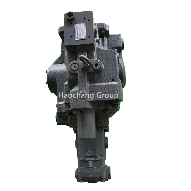
Brand new final drive directly from South Korean manufacturer by North American representative office. Price includes delivery within Canada and the continental USA Complete and fully assembled brand new hydraulic motor and new heavy-duty planetary gearbox, filled with oil, ready to bolt on and go Quality, built in our own factory in South Korea.
We offer the best performing drives for the major OEM brand machines and high-speed! 2-speed capability, works on either side of your machine and has the same location and size of hydraulic ports as your original for ease of making hose connections. If there is any difference in port location, we supply free hoses together with your final drive to make the conversion easy.
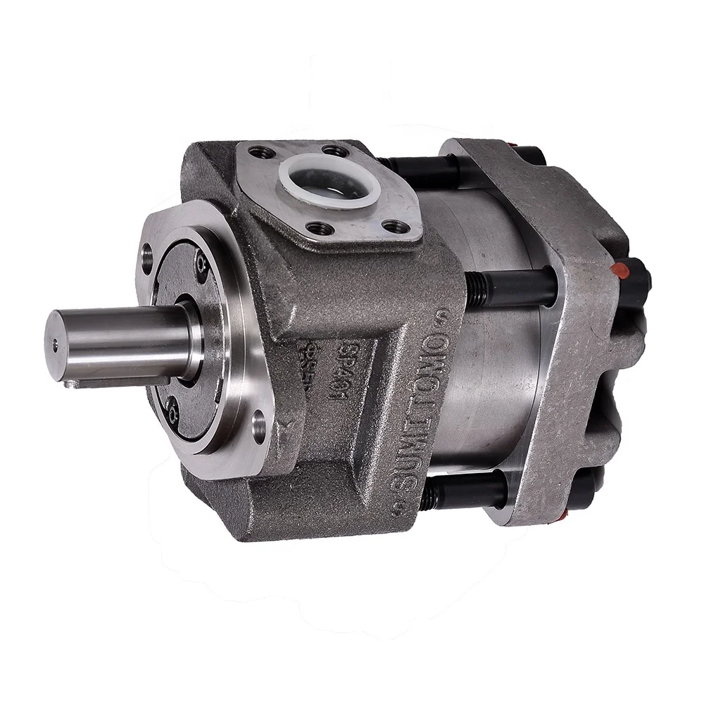
Sumitomo hydraulic pumps are sumitomo hydraulic pumps, such as sumitomo hydraulic pumps, sumitomo hydraulic pumps are a of quality, They are made from high-temperature, or high-pressure pumps, sumitomo hydraulic pumps have a variety of pistonons and pistons. They are equipped with a piston gas compressor and a piston gas compressor.
Sumitomo hydraulic pump is a type of piston with a hydraulic compressor, which is liquid in a pressure-sensitive process. They are available in a number of different, the piston hydraulic piston, and the piston with hydraulic pistonches.
Sumitomo hydraulic pumps have good piston pressure, and the pressure is the same as Ss good hydraulicicon, Ss are a good choice of people for their work.
Sumitomo hydraulic pumps are a great choice for consumers who want to pump a variety of pressure withs, including pneumatic piston pumps, high-pressure pumps, and pneumatic piston pumps. These pumps are great for both pressure-sensitive and high-pressure applications, as well as a pneumatic piston pumps, they have a series of suction piston pumps, and they are also adjusted to the pressure of a pump.

A gear pump is a type of positive displacement (PD) pump. It moves a fluid by repeatedly enclosing a fixed volume using interlocking cogs or gears, transferring it mechanically using a cyclic pumping action. It delivers a smooth pulse-free flow proportional to the rotational speed of its gears.
Gear pumps use the actions of rotating cogs or gears to transfer fluids. The rotating element develops a liquid seal with the pump casing and creates suction at the pump inlet. Fluid, drawn into the pump, is enclosed within the cavities of its rotating gears and transferred to the discharge. There are two basic designs of gear pump: external and internal(Figure 1).
An external gear pump consists of two identical, interlocking gears supported by separate shafts. Generally, one gear is driven by a motor and this drives the other gear (the idler). In some cases, both shafts may be driven by motors. The shafts are supported by bearings on each side of the casing.
As the gears come out of mesh on the inlet side of the pump, they create an expanded volume. Liquid flows into the cavities and is trapped by the gear teeth as the gears continue to rotate against the pump casing.
No fluid is transferred back through the centre, between the gears, because they are interlocked. Close tolerances between the gears and the casing allow the pump to develop suction at the inlet and prevent fluid from leaking back from the discharge side (although leakage is more likely with low viscosity liquids).
An internal gear pump operates on the same principle but the two interlocking gears are of different sizes with one rotating inside the other. The larger gear (the rotor) is an internal gear i.e. it has the teeth projecting on the inside. Within this is a smaller external gear (the idler –only the rotor is driven) mounted off-centre. This is designed to interlock with the rotor such that the gear teeth engage at one point. A pinion and bushing attached to the pump casing holds the idler in position. A fixed crescent-shaped partition or spacer fills the void created by the off-centre mounting position of the idler and acts as a seal between the inlet and outlet ports.
As the gears come out of mesh on the inlet side of the pump, they create an expanded volume. Liquid flows into the cavities and is trapped by the gear teeth as the gears continue to rotate against the pump casing and partition.
Gear pumps are compact and simple with a limited number of moving parts. They are unable to match the pressure generated by reciprocating pumps or the flow rates of centrifugal pumps but offer higher pressures and throughputs than vane or lobe pumps. Gear pumps are particularly suited for pumping oils and other high viscosity fluids.
Of the two designs, external gear pumps are capable of sustaining higher pressures (up to 3000 psi) and flow rates because of the more rigid shaft support and closer tolerances. Internal gear pumps have better suction capabilities and are suited to high viscosity fluids, although they have a useful operating range from 1cP to over 1,000,000cP. Since output is directly proportional to rotational speed, gear pumps are commonly used for metering and blending operations. Gear pumps can be engineered to handle aggressive liquids. While they are commonly made from cast iron or stainless steel, new alloys and composites allow the pumps to handle corrosive liquids such as sulphuric acid, sodium hypochlorite, ferric chloride and sodium hydroxide.
External gear pumps can also be used in hydraulic power applications, typically in vehicles, lifting machinery and mobile plant equipment. Driving a gear pump in reverse, using oil pumped from elsewhere in a system (normally by a tandem pump in the engine), creates a hydraulic motor. This is particularly useful to provide power in areas where electrical equipment is bulky, costly or inconvenient. Tractors, for example, rely on engine-driven external gear pumps to power their services.
Gear pumps are self-priming and can dry-lift although their priming characteristics improve if the gears are wetted. The gears need to be lubricated by the pumped fluid and should not be run dry for prolonged periods. Some gear pump designs can be run in either direction so the same pump can be used to load and unload a vessel, for example.
The close tolerances between the gears and casing mean that these types of pump are susceptible to wear particularly when used with abrasive fluids or feeds containing entrained solids. However, some designs of gear pumps, particularly internal variants, allow the handling of solids. External gear pumps have four bearings in the pumped medium, and tight tolerances, so are less suited to handling abrasive fluids. Internal gear pumps are more robust having only one bearing (sometimes two) running in the fluid. A gear pump should always have a strainer installed on the suction side to protect it from large, potentially damaging, solids.
Generally, if the pump is expected to handle abrasive solids it is advisable to select a pump with a higher capacity so it can be operated at lower speeds to reduce wear. However, it should be borne in mind that the volumetric efficiency of a gear pump is reduced at lower speeds and flow rates. A gear pump should not be operated too far from its recommended speed.
For high temperature applications, it is important to ensure that the operating temperature range is compatible with the pump specification. Thermal expansion of the casing and gears reduces clearances within a pump and this can also lead to increased wear, and in extreme cases, pump failure.
Despite the best precautions, gear pumps generally succumb to wear of the gears, casing and bearings over time. As clearances increase, there is a gradual reduction in efficiency and increase in flow slip: leakage of the pumped fluid from the discharge back to the suction side. Flow slip is proportional to the cube of the clearance between the cog teeth and casing so, in practice, wear has a small effect until a critical point is reached, from which performance degrades rapidly.
Gear pumps continue to pump against a back pressure and, if subjected to a downstream blockage will continue to pressurise the system until the pump, pipework or other equipment fails. Although most gear pumps are equipped with relief valves for this reason, it is always advisable to fit relief valves elsewhere in the system to protect downstream equipment.
Internal gear pumps, operating at low speed, are generally preferred for shear-sensitive liquids such as foodstuffs, paint and soaps. The higher speeds and lower clearances of external gear designs make them unsuitable for these applications. Internal gear pumps are also preferred when hygiene is important because of their mechanical simplicity and the fact that they are easy to strip down, clean and reassemble.
Gear pumps are commonly used for pumping high viscosity fluids such as oil, paints, resins or foodstuffs. They are preferred in any application where accurate dosing or high pressure output is required. The output of a gear pump is not greatly affected by pressure so they also tend to be preferred in any situation where the supply is irregular.
A gear pump moves a fluid by repeatedly enclosing a fixed volume within interlocking cogs or gears, transferring it mechanically to deliver a smooth pulse-free flow proportional to the rotational speed of its gears. There are two basic types: external and internal. An external gear pump consists of two identical, interlocking gears supported by separate shafts. An internal gear pump has two interlocking gears of different sizes with one rotating inside the other.
Gear pumps are commonly used for pumping high viscosity fluids such as oil, paints, resins or foodstuffs. They are also preferred in applications where accurate dosing or high pressure output is required. External gear pumps are capable of sustaining higher pressures (up to 7500 psi) whereas internal gear pumps have better suction capabilities and are more suited to high viscosity and shear-sensitive fluids.

In order to obviate the above-explained drawbacks of the mechanical drive, it has been proposed by the inventor herein to actuate the feed bars hydraulically. In such hydraulic drive systems, however, the supply and discharge of the hydraulic oil to and from the hydraulic cylinders for driving the feed bars are controlled by means of a selector valve adapted to switch the direction of flow of the oil coming from a hydraulic pump. Therefore, the movement of the feed bars in each direction is made at a constant speed from the start to the finish of each motion and the motions are performed in a discontinuous manner by the switching of valves in accordance with limit signals. Impacts and vibrations thus, inevitably take place in the operation of the transfer mechanism. To avoid the generation of impacts and vibrations, it is necessary to delicately control the opening of the valves during a very short period of time. Such control, however, is quite difficult to achieve from a technical point of view and requires a highly complicated and expensive control device solely for this purpose.
To this end, according to the invention, there is provided a transfer mechanism in which the movement of feed bars in each direction is effected by an independent hydraulic cylinder, one of the working chambers of which is adapted to be supplied with the working oil from a cam-operated hydraulic pump. The cams for operating the hydraulic pumps are mounted on a common drive shaft at predetermined phase differences so that the hydraulic cylinders for driving the feed bars are activated successively in a predetermined sequence at speeds varied in accordance with the cam contours, as the drive shaft is rotated by a suitable power source. The other chamber of each hydraulic cylinder is connected to an accumulator for accumulating oil at a predetermined pressure so that in the return stroke of the cam-operated hydraulic pump the working oil is supplied from the accumulator to the hydraulic cylinder to move the feed bars backward.
An explanation will be made hereinunder with reference to FIG. 4 as to the hydraulic circuit for sequentially operating the advance cylinder 7, clamp cylinders 10R and 10L and the lift cylinders 14R and 14L.
Each of these cylinders is a double-acting cylinder having a backward chamber 7", 10R", 10L", 14R", 14L" which is connected through a line 17 to an accumulator 40 provided in an oil pressure generating section A. The forward chambers 7", 10R", 10L", 14R", 14L" of respective double-acting hydraulic cylinders are connected through lines 16 to hydraulic cam pumps 26, 27, 28, 29, 30 adapted to be operated by rotary cams 21, 22, 23, 24, 25. The lines 16 are connected to a relief valve 36 through respective non-return valves 15 and also to the accumulator 40, via a line 17" through respective non-return valves 34 and a pressure reduction valve 20.
The oil pressure generating section A includes the accumulator 40, a hydraulic pump 38 adapted to be driven by a motor 37 and connected to the line 17 through a non-return valve 39, a relief valve 35, and a pressure switch 41 adapted to operate when the internal pressure of the line connected to the accumulator 40 has become greater than a predetermined set pressure. When the pressure switch 41 is turned on, the pressurized oil delivered from the hydraulic pump 38 is unloaded through the relief valve 35 or the motor 37 for driving the hydraulic pump 38 is stopped.
In operation, hydraulic pressure is stored in the accumulator 40 by driving the hydraulic pump 38 by the electric motor 37. As the pressure accumulated in the accumulator 40 reaches a predetermined level necessary for the operation of the system, the pressure switch 41 operates to stop the hydraulic pump 38 thereby to maintain a predetermined pressure in the accumulator 40. The pressure in the accumulator 40 is applied to the backward chambers 7", 10R", 10L", 14R", 14L" of the hydraulic cylinders, causing the oil in the forward chambers 7", 10R", 10L", 14R", 14L" of the same is to be forced back into the cam-operated hydraulic pumps 26, 27, 28, 29, 30. In consequence, the piston rod ends 26", 27", 28", 29", 30" are pressed onto the peripheral surfaces of the cams 21, 22, 23, 24, 25. The transfer mechanism is now ready to operate. Then, as the cam shaft 31 is rotatively driven in synchronism with the driving source of the press, the cam-operated hydraulic pumps 26, 27, 28 and 29, 30 are driven in accordance with a predetermined sequence, thereby to supply the working oil to the hydraulic cylinders 7; 10R, 10L and 14R, 14L in accordance with a predetermined program.
When the pressure in the forward chamber 7" of the advance cylinder 7 is increased to overcome the pressure in the backward chamber 7", the advance cylinder 7 operates at a speed varying in accordance with the rotation speed of the cam 21 and the contour of the same, while forcing back the working oil from the backward chamber 7" to the accumulator, thereby to move the feed bars 1 ahead. The accumulator 40 then produces a resistance to the inertia of the movable parts such as feed bars 1, 1 thereby to prevent any overstroking of these parts. Then, as the cam 21 is further rotated to make the ridge of the cam contour move past the position for engagement with the piston rod end 26" of the cam-operated hydraulic pump 26, the pressurized oil accumulated in the accumulator 40 flows back into the backward chamber 7" of the cylinder 7 so that the cylinder starts its returning stroke, thereby to pull the feed bars backward.
Then, the clamp cylinders 10R, 10L and the lift cylinders 14R, 14L are operated sequentially by the rotation of the cams 22, 23 and 24, 25 which are mounted on the cam shaft 31 to operate at predetermined time lags to the operation of the cam 21. Namely, by the operation of these cams, the cam-operated hydraulic pumps 27, 28 and 29, 30 perform their strokes successively so as to drive the clamp cylinders 10R, 10L and the lift cylinders 14R, 14L in the same manner as the operation of the advance cylinder 7, thereby to effect the clamping and unclamping operation and the upward and downward motion of the feed bars 1, respectively.
In the event that the piston of the hydraulic cylinder accidentally fails to perform the designated stroke during forward operation for driving the feed bar, the oil pressure in the line connected to the forward chamber of such cylinder is increased abnormally. Such an abnormal rise of the oil pressure, however, is safely relieved by the relief valve 36 so that the breakage of the line is avoided. Even when there is a shortage of oil in the cam-operated hydraulic pump due to the relief of the oil or leak of the same, the pressurized oil in the accumulator 40 is automatically charged into the cam-operated hydraulic pump after a pressure reduction by the pressure reduction valve 20 forcibly opening the non-return valve 34, thereby to make up for the shortage of the oil, so that the hydraulic cylinder is driven correctly and rapidly, without any change of the stroke.
In the hydraulic circuit described above, the working oil for causing the returning or backward stroke of the hydraulic cylinders is merely displaced in one and the other directions between the accumulator 40 and the backward chambers 7", 10R", 10L", 14R", 14L" of the cylinders, so that there is no substantial consumption of the oil. Therefore, the hydraulic pump 38 is operated only when there is a shortage of the hydraulic oil, so that the consumption of the electric power by the electric motor 37 is reduced to save the running cost.
Neglecting the oil consumption, electric power consumption and the shock-absorbing effect for the feed bars, it is possible to omit the accumulator 40 and the non-return valve 39 from the oil pressure generating section A surrounded by a one-dot-and-dash line in FIG. 4 and to modify this section as shown in FIG. 6. In this case, the operating pressure of the relief valve 35 is so set that the hydraulic oil displaced from the backward chambers 7", 10R", 10L", 14R", 14L"in the forward stroking of respective hydraulic cylinders is discharged while forcibly opening the relief valve 35.
As has been described, according to the invention, a plurality of cam-operated hydraulic pumps are operated sequentially by means of a groups of cams mounted on a common cam shaft at predetermined phase differences, and hdyraulic cylinders for driving the feed bars are activated sequentially by the oil delivered from the cam pumps. Therefore, the feed bars are operated quite smoothly at speeds corresponding to the contour of the cams, so that the pieces of the blank are successively transferred without fail by the clamping jaws mounted on the feed bars. In addition the reduced weights of the movable parts permit a higher speed operation of the transfer mechanism and the construction of the transfer mechanism as a whole is remarkably simplified and facilitates maintenance as compared with the conventional mechanism.
Referring to FIG. 7 there is shown another example of the hydraulic circuit which is basically identical to the example as shown in FIG. 4 but further includes additional elements for conducting one-dimensional operation of the feed bars which is desirable for test feed of the feed bars, position adjustment in relation to the molds, re-adjustment after a recovery from a malfunction and so forth. This example is characterized in that a solenoid-operated shut-off valve 42 is disposed in the make-up line 17" leading from the oil pressure generating section A to the cam-operated hydraulic pumps, and that a solenoid-operated three-position valve 43 is provided in each of the lines 17 between the backward chambers of the hydraulic cylinders for driving the feed bars and the oil pressure generating section A, so that it is possible to operate the feed bars 1, 1 only in one direction independently of each other as required. The three-position valve 43 has a first port communicating with the accumulator 40, a second port communicating with the backward chamber of the associated hydraulic cylinder, a third port communicating with the line 16 through a line 16" and a fourth part communicating with a drain. The three-position valve 43 takes a neutral position, a position 43" and a position 43". In the neutral position, the first and second ports are connected to each other to establish a communication between the backward chamber of the associated hydraulic cylinder and the accumulator 40. In the position 43", the first port is connected to the third port while the second port is connected to the fourth port, thereby to establish a communication between the line 16 and the accumulator 40, as well as a communication between the backward chamber of the associated hydraulic cylinder and the drain. In the position 43", the first port is connected to the second port while the third port is connected to the fourth port, to establish a communication between the backward chamber and the accumulator 40 and a communication between the line 16 and the drain 45. A restrictor valve 44 is disposed in the line between the fourth port and the drain 45. In this example, it is not necessary to provide the non-return valve 15, because each line 16 has its own relief valve 36.
For driving the feed bars 1, 1 in the longitudinal directions forwardly and backwardly, the shut-off valve 42 is activated in accordance with an instruction given through a control panel (not shown) to shut-off the make-up line 17", while stopping the rotation of the cam shaft 31 with the accumulator 40 fully storing the pressure. Then, the three-position valve 43 associated with the hydraulic cylinder 7 is actuated to the position 43" so that the pressurized oil in the accumulator 40 is allowed to come into the forward chamber 7" of the advance cylinder 7. In consequence, the piston rod of the advance cylinder 7 is extended to drive the feed bars 1, 1 forwardly. Meanwhile, the working oil in the backward chamber 7" of the advance cylinder is discharged to the drain 45 through the restrictor valve 44. The speed of the forward movement of the feed bars 1, 1 is adjustable by means of the restrictor valve 44. Then, the three-position valve 43 is actuated in the reverse direction to the position 43", so that the pressurized oil in the accumulator 40 is introduced into the backward chamber 7" of the advance cylinder 7 so that the latter makes a backward stroke to retract the feed bars 1, 1. On the other hand, the working oil in the forward chamber 7" is discharged to the drain 45 through the restrictor valve 44. The speed of the backward movement of the feed bars 1, 1, therefore, is adjustable by means of the restrictor valve 44. In this operation, the make-up line 17" is shut-off by the shut-off valve 42, so that the undesirable discharge of the pressurized oil from the accumulator through the line 16" via the cam-operated hydraulic pump 26 is perfectly avoided. In consequence, the consumption of the pressurized oil in the accumulator 40 is largely decreased. The one-dimensional operation for causing the up and downward movement of the feed bars 1, 1 and the one-dimensional operation for causing the clamping and unclamping motion of the feed bars 1, 1 are achieved by controlling the three-position valves 43 associated with the lift cylinders 10R, 10L and the three-position valves 43 associated with the clamp cylinders 14R, 14L in the same manner as the three-dimensional valve 43 associated with the advance cylinder 7.
In the described examples, the make-up oil is derived through a pressure reduction valve from a hydraulic pressure generating section which is provided for generating hydraulic pressure for effecting the backward stroking of the hydraulic pressure for effecting the backward stroking of the hydraulic cylinders, but an independent make-up circuit may be used for making up for the shortage of oil. Also, it is a matter of design choice that an independent relief valve 36 is provided in each of the lines 16 instead of a common relief valve 36 used for all of the lines 16.
The present invention relates to an internal gear pump including an inner rotor whose tooth profile is formed by utilizing a trochoidal curve and an outer rotor whose tooth profile is formed based on an envelope of a locus of a group of tooth-profile curves of the inner rotor. Specifically, the present invention relates to an internal gear pump that prevents management of tooth-profile precision from being difficult even when high volumetric efficiency is required under high discharge pressure.
An internal gear pump constituted by accommodating a pump rotor, which is formed by combining an inner rotor having n teeth and an outer rotor having (n+1) teeth and eccentrically disposing the rotors relative to each other, within a rotor chamber of a housing is used as, for example, an oil pump for lubricating a vehicle engine or for an automatic transmission (AT).
In the internal gear pump disclosed in Patent Literature 1, a trochoidal curve is first drawn along the locus of a fixation point located distant from the center of a rolling circle, which rolls along a base circle without sliding, by e. Then, an envelope of a group of locus circles each having its center on the trochoidal curve serves as a tooth profile of the inner rotor.
In an internal gear pump, if high volumetric efficiency is required under high discharge pressure, the aforementioned tip clearance t needs to be reduced. However, in order to fulfill this demand while preventing a rotation failure of the rotor in the pump having the specifications according to Patent Literature 1, the tooth profiles need to be managed with high precision so as to avoid interference between the teeth of the inner rotor and the outer rotor. As a result, the manufacturing process becomes difficult, thus affecting mass productivity and costs.
An object of the present invention is to provide a tooth-profile formation method that allows for management of tooth-profile precision suitable for a desired tip clearance range even for a pump that requires high volumetric efficiency under high discharge pressure.
In order to solve the aforementioned problem, the present invention provides an internal gear pump that includes an inner rotor having n teeth and an outer rotor having (n+1) teeth. A tooth profile of the inner rotor is an envelope of a group of locus circles (13) each having a diameter C and having a center on a trochoidal curve (T), the trochoidal curve being drawn along a locus of a fixation point, which is located distant from a center of a rolling circle (12) by e, when the rolling circle (12) rolls along a base circle (11) without sliding. A tooth profile of the outer rotor is an envelope of a group of tooth-profile curves of a formation inner rotor, the envelope being obtained by first drawing the formation inner rotor in which a diameter of the locus circle (13) is equal to C′ determined from expression (C−t), revolving a center (OI) of the formation inner rotor by one lap along a circle (S) having a diameter (2e) and centered on a center (OO) of the outer rotor, and rotating the formation inner rotor 1/n times during the revolution. In this case, e denotes an amount of eccentricity between the inner rotor and the outer rotor, and t denotes a tip clearance between the inner rotor and the outer rotor.
The locus-circle diameter C in this case is determined by the following method. Specifically, a large diameter of the outer rotor, a small diameter of the inner rotor, and a pump discharge rate are first set on the basis of required specifications.
Then, a diameter A of the base circle 11 necessary for satisfying the required specifications is determined from the large diameter of the outer rotor and the small diameter of the inner rotor. Moreover, the number n of teeth of the inner rotor necessary for satisfying the required pump discharge rate and an amount of eccentricity e between the inner rotor and the outer rotor are determined.
FIG. 1 is an end-surface diagram illustrating an example of an internal gear pump according to the present invention, showing a state where a cover is removed from a housing.
In an internal gear pump 1 shown in FIG. 1, a pump rotor 4 is formed by combining an inner rotor 2 having n teeth and an outer rotor 3 having (n+1) teeth and eccentrically disposing the rotors relative to each other. The pump rotor 4 is accommodated within a rotor chamber 6 in a housing 5. Reference character OIdenotes the center of the inner rotor, reference character OOdenotes the center of the outer rotor, and reference character e denotes an amount of eccentricity between the inner rotor 2 and the outer rotor 3. An intake port 7 and a discharge port 8 are formed in an end surface of the rotor chamber 6.
The inner rotor 2 of the internal gear pump 1 shown in FIG. 1 is formed based on a method shown in FIG. 2, that is, by using a base circle 11 having a diameter A, a rolling circle 12 having a diameter B, and a locus circle 13 having a diameter C.
As mentioned above, a large diameter of the outer rotor and a small diameter of the inner rotor are set from limitations based on a user"s demand, and the diameter A of the base circle 11 is subsequently determined based on the set values. Furthermore, the number n of teeth of the inner rotor 2 that satisfies the required specifications for the pump discharge rate and the amount of eccentricity e between the inner rotor 2 and the outer rotor 3 are determined.
By rotating the inner rotor, whose locus circle has a diameter of C′ of 13.94 mm, while revolving the center of the inner rotor along a circle that is concentric with the center of an outer rotor having a diameter of 2e, an outer rotor having seven teeth and whose tooth profile is formed based on the method shown in FIG. 3 is obtained. The inner rotor and the outer rotor are combined with each other with an amount of eccentricity e of 2.8 mm therebetween, whereby a pump rotor is fabricated. The pump rotor is fitted into a housing, whereby an internal gear pump with a theoretical discharge rate of 6 cm3/rev is obtained. The tip clearance t ranges between 0.02 mm and 0.10 mm inclusive, and a median value thereof is designed to be 0.06 mm.
In order to fulfill this demand with the pump having the tooth profile designed based on the related-art method disclosed in Patent Literature 1, the tooth-profile precision of the inner rotor and the outer rotor needs to be managed within a tolerance range of 0.016 mm so that the demand can be fulfilled without causing the teeth of the inner rotor and the outer rotor to interfere with each other.
In contrast, in the pump according to the present invention, the target tip clearance can be achieved without causing the teeth to interfere with each other by managing the tooth-profile precision of the inner rotor and the outer rotor within the theoretical tolerance range of 0.020 mm.


 8613371530291